★ TRUSTED BY 321,897+ PROFESSIONALS WORLDWIDE
🏒
Trusted Business
Verified & Licensed
πŸ›‘οΈ
Virus Free Files
100% Safe Downloads
πŸ”’
Secure Payment
SSL Protected
⚑
Instant Delivery
Available Immediately
Sale!

Clark CGC CGP CDP 20-30 Forklift Shop Manual – Service, Repair & Specifications PDF

Original price was: $49.95.Current price is: $29.95.

Comprehensive 961-page CLARK shop manual for CGC, CGP and CDP 20-30 lift trucks, covering scheduled maintenance, S4S diesel, 4G64 gas/LPG/CNG and GM 3.0L LPG engines, standard and hydrostatic transmissions, electrical systems, brakes, steering, hydraulics, uprights, chassis and truck specifications.

⚑
Instant PDF Download
Available immediately
πŸ’Ύ
Save to Your Device
Download & keep forever
πŸ›‘οΈ
Antivirus Scanned
100% virus-free
🌍
Trusted Worldwide
175,000+ customers

Description

Clark CGC CGP CDP 20-30 Forklift Shop Manual – Service, Repair & Specifications PDF

The Clark CGC CGP CDP 20-30 Forklift Shop Manual – Service, Repair & Specifications PDF is a large technical workshop reference for CLARK CGC, CGP and CDP 20-30 lift trucks. It combines maintenance schedules, troubleshooting, inspection procedures, adjustments, component removal and installation, overhaul information, hydraulic and electrical schematics, service limits, torque data and truck specifications in one 961-page PDF. The manual addresses both standard transaxle and hydrostatic transmission configurations and includes gasoline, LPG/CNG and diesel engine service information shown in the publication.

File Details

  • Manual type: Shop Manual
  • Brand: CLARK
  • Models: CGC, CGP, CDP 20-30
  • Language: English
  • Page count: 961 pages
  • File format: PDF
  • Publication identification: SM 598 / SM-598S markings appear throughout the manual
  • Cover identification: Volume 1 of 2, Groups 00-03
  • Publication dates visible in the file: October 1994, April 1996 and February 1998 revisions/pages

Equipment and Powertrain Coverage

This Clark CGC CGP CDP 20-30 shop manual covers the 20, 25 and 30 model families and includes procedures for the standard transaxle as well as the hydrostatic drive system used on the H variants. Engine material includes the Mitsubishi S4S diesel engine, Mitsubishi 4G64 gas/LPG/CNG engine and General Motors 3.0L LPG engine. The S4S section incorporates detailed engine specifications, maintenance standards, special tools, disassembly, inspection, repair and reassembly procedures. The file also contains dedicated fuel-system sections for carbureted LPG and gasoline systems, plus cooling, ignition, electrical and air-induction material.

The cover identifies the publication as Volume 1 of 2, Groups 00-03. The PDF file itself also contains later service groups through Group 40, including transmission, ignition, electrical, wheels and tires, brakes, steering, hydraulics, uprights, chassis and general specifications. That broader content makes this copy useful for work extending well beyond engine and fuel-system service.

Chapters Covered

  • Group SA – Safe Maintenance
    • Safety signs and safe maintenance practices
    • Lifting, jacking, blocking and towing procedures
  • Group PS – Periodic Service
    • Maintenance schedules and service intervals
    • Planned Maintenance Program and inspection procedures
    • PM inspection report
  • Group 00(D) – S4S Diesel Engine
    • Engine oil and filter, throttle linkage and fuel supply
    • RPM settings, stall tests, compression checks and engine removal
    • Mitsubishi S4S engine service information, maintenance standards and special tools
    • Cylinder head, valves, timing gears, camshaft, pistons, crankshaft, lubrication, cooling, fuel and electrical systems
    • Engine troubleshooting, overhaul and balancer supplement
  • Group 00(G) – 4G64 Gas/LPG/CNG Engine
    • Specifications and description
    • Troubleshooting, oil and filter, tune-up and RPM/vacuum/stall checks
    • Compression checks, removal and replacement, and overhaul
  • Group 00(GM) – General Motors 3.0L LPG Engine
    • Specifications and description
    • Troubleshooting, engine oil and filter, tune-up and performance checks
    • Compression test, engine removal/replacement and overhaul
  • Group 01 – Engine Cooling System
    • Cooling system specifications and troubleshooting
    • Testing, maintenance, belt service and radiator removal/replacement
  • Group 02(LP) – LPG Fuel System
    • System specifications and troubleshooting
    • Adjustments and maintenance
    • Carburetor, throttle body, vaporizer and fuel-lock overhaul
  • Group 02(G) – Gasoline-Carb Fuel System
    • Specifications, description and troubleshooting
    • Checks and adjustments
    • Carburetor overhaul, fuel pump and filter service
  • Group 03 – Air Induction and Exhaust Systems
    • Specifications and system description
    • Air-induction troubleshooting and service
    • Exhaust-system service
  • Group 06(S) – TA-30 Standard Transaxle
    • Specifications, troubleshooting, oil/filter and oil cooler
    • Removal and replacement, transaxle overhaul, drive axle ends and control valve
  • Group 06(H) – Hydrostatic Transmission
    • Transmission specifications and description
    • Control-system troubleshooting, diagnostic control and adjustment
    • Component removal, drive pump and drive motor service, drive axle ends
  • Group 12 – Ignition System
    • Specifications, troubleshooting, inspection, adjustment and timing
    • GM 3.0L ignition timing and distributor overhaul
  • Group 13 – Instrument Pod
    • Description and specifications
    • Troubleshooting, removal and installation
  • Group 14 – Electrical System
    • Electrical specifications and wiring diagrams
    • Starter, battery and alternator troubleshooting
    • Starter and alternator maintenance and overhaul
  • Group 22 – Wheels and Tires
    • Specifications and description
    • Cushion and pneumatic wheel/tire service
  • Group 23 – Brake/Inching System
    • Standard and hydrostatic brake/inching coverage
    • Service brake troubleshooting, pedal/linkage adjustment, bleeding and overhaul
    • Master cylinder and parking brake service
  • Group 25 – Steering Column and Gear
    • Steering specifications, checks, adjustments and component service
  • Group 26 – Steer Axle
    • Steer axle specifications, inspection and service procedures
  • Group 29 – Hydraulic Sump, Filters and Pump
    • Specifications, hydraulic-pump troubleshooting and fluid/filter maintenance
    • Pump removal, replacement and overhaul
  • Group 30 – Hydraulic Control Valve/Lift Circuit
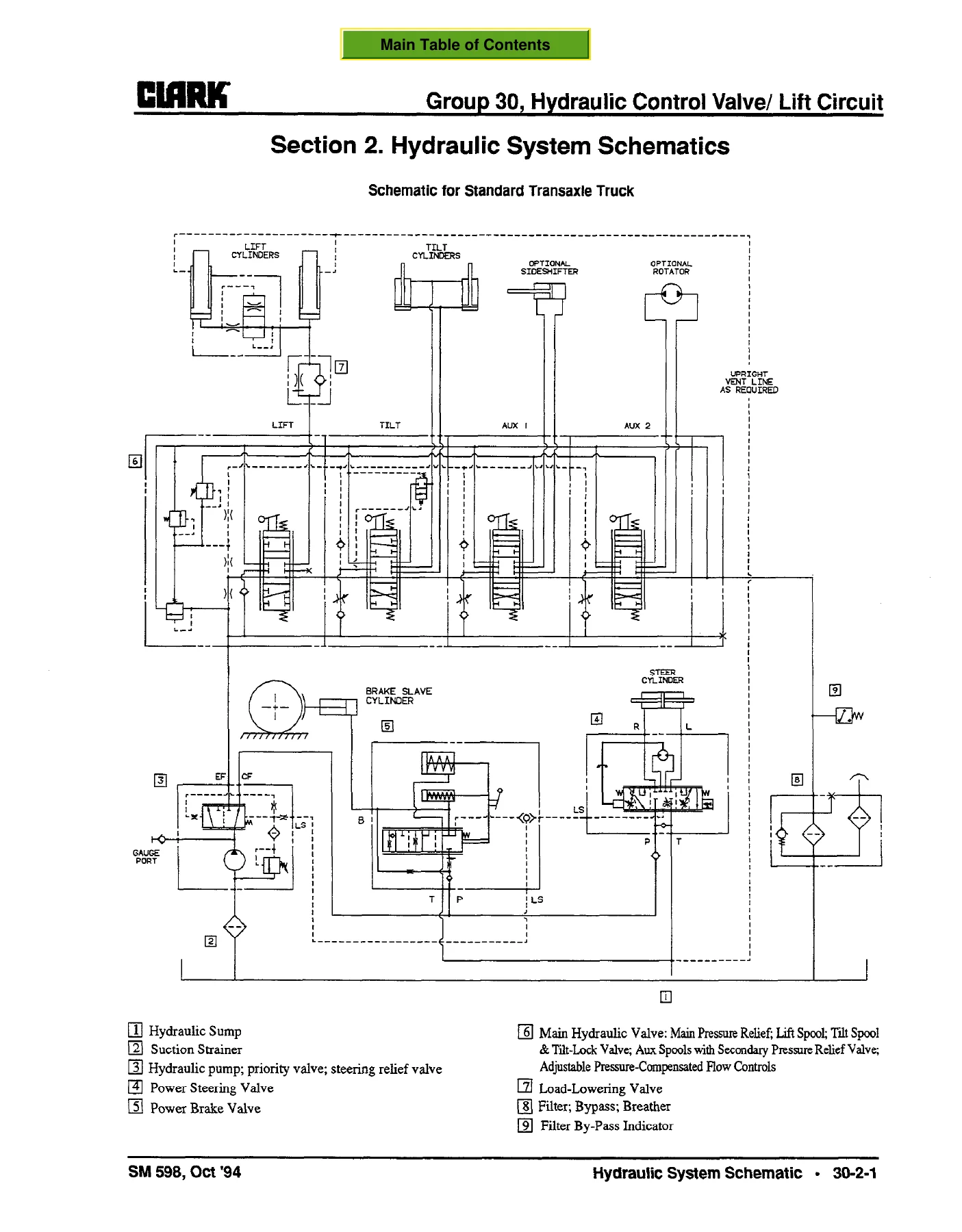
    • Specifications and hydraulic system schematics
    • Troubleshooting, pressure checks and adjustments
    • Control-valve removal, replacement and overhaul
  • Group 32 – Tilt Cylinders
    • Specifications, checks and adjustments
    • Cylinder removal, replacement and overhaul

    Complete PDF Bookmark Tree

    Complete Bookmarks

    The complete bookmarks in the β€œClark CGC CGP CDP 20-30 Forklift Shop Manual – Service, Repair & Specifications PDF” are as follows:

    Title Pagep. 1
    Use of this Manualp. 2
    Contentsp. 3
    SAFE MAINTENANCEp. 4
    Section 1. Safetyp. 5
    Lifting, Jacking, and Blockingp. 7
    Safe Parkingp. 8
    Lifting, Blocking, and Jacking Pointsp. 8
    Raising Drive Wheels Off Floorp. 8
    Raising Truck with A Hoistp. 9
    Blocking the Upright In Raised Positionp. 10
    Raising Rear of Truckp. 10
    Raising Entire Truckp. 11
    Shipping Tie-Down Instructionsp. 12
    Towingp. 13
    PERIODIC SERVICEp. 15
    Maintenance Schedulesp. 16
    β€œPeriodic Service”p. 16
    Determining Maintenance Intervalsp. 16
    Service Chart/Lubrication Pointsp. 17
    Recommended Periodic Service Schedulep. 18
    The Planned Maintenance Programp. 21
    introduction to Planned Maintenancep. 22
    The Basic PM Proceduresp. 22
    Recommended PM Task Chartp. 23
    Visual Inspectionp. 24
    Functional Testsp. 25
    Air Cleaning the Truckp. 27
    Truck Chassis Inspection and Lubricationp. 28
    Upright and Tilt Cylinder Lubricationp. 28
    Lift Chain Lubricationp. 28
    Under-the-Hood inspectionp. 28
    Fluid Checksp. 28
    Stall Testp. 29
    Cranking Voltage Testp. 29
    Critical Fastener Torque Checksp. 29
    The PM Inspection Formp. 30
    S4S DIESEL ENGINEp. 31
    Engine Oil and Filterp. 32
    Throttle Linkage Checks and Adjustmentp. 34
    . Fuel Supply Systemp. 36
    RPM Settings and Stall Testsp. 37
    Engine Removal and Replacementp. 39
    S4S Diesel Engine Service Manualp. 45
    HOW TO USE THIS MANUALp. 46
    GENERALp. 48
    SPECIFICATIONSp. 49
    SECTIONAL VIEWSp. 52
    PERFORMANCE CURVESp. 56
    MAINTENANCE STANDARDSp. 58
    MAINTENANCE STANDARDSp. 59
    TIGHTENING TORQUEp. 68
    SEALANT APPLICATION DATAp. 72
    SPECIAL TOOL LISTp. 73
    ENGINE PROPERp. 76
    CYLINDER HEAD AND VALVE MECHANISMp. 77
    TIMING β€˜GEARS, CAMSHAFT AND OIL PANp. 92
    FLYWHEELp. 105
    PISTONS, CONNECTING RODS, CRANKSHAFT AND CRANKCASEp. 111
    INLET AND EXHAUST SYSTEMSp. 135
    DESCRIPTIONp. 136
    EXHAUST MANIFOLDp. 136
    LUBRICATION SYSTEMp. 137
    DESCRIPTIONp. 138
    Oil Pumpp. 139
    OIL FILTERp. 144
    RELIEF VALVEp. 145
    COOLING SYSTEMp. 146
    DESCRIPTIONp. 147
    PUMPp. 148
    THERMOSTATp. 149
    FUEL SYSTEMp. 150
    DESCRIPTIONp. 151
    FUEL FILTERp. 155
    INJECTION NOZZLESp. 156
    INJECTION PUMPp. 160
    ELECTRICAL SYSTEMp. 163
    STARTERp. 164
    ALTERNATORp. 172
    HEATER PLUGSp. 177
    WORKSHOP THEORYp. 178
    SUGGESTIONS ON DISASSEMBLY ANDp. 179
    TESTING THE COMPRESSIONp. 182
    TROUBLESHOOTINGp. 183
    TROUBLESHOOTING CHART (1)p. 184
    TROUBLESHOOTING CHART (2)p. 188
    Balancer for S4S Diesel Enginep. 191
    4G64 GAS/LPG/CNG ENGINEp. 193
    Engine Specificationsp. 194
    Engine Troubleshootingp. 195
    Engine Oil and Filterp. 199
    Engine Tune-Upp. 201
    RPM, Vacuum, and Stall Testsp. 202
    Introductionp. 202
    Test Proceduresp. 203
    Analysis of Stall Testp. 205
    Compression Checksp. 206
    Engine Removal and Replacementp. 208
    Engine Overhaulp. 214
    Overhaul Specificationsp. 215
    Service Precautionsp. 219
    Tightening Method for Permanentlyp. 220
    Special Toolsp. 221
    OVERHAUL PROCEDURESp. 223
    GM ENGINEp. 259
    Specificationsp. 260
    Troubleshootingp. 261
    Oil and Filterp. 265
    Tune-Upp. 267
    RPM, Vacuum, and Stall Testsp. 268
    Introductionp. 268
    Test Proceduresp. 269
    Analysis of Stall Testp. 271
    Compression Checksp. 272
    Removal and Replacementp. 274
    Engine Removalp. 275
    Engine Replacementp. 277
    Engine Overhaulp. 280
    Contentsp. 281
    Specificationsp. 284
    ENGINE COOLINGp. 363
    Specifications and Descriptionp. 364
    Troubleshootingp. 367
    Testing and Maintenancep. 368
    Cooling System and Alternator Belt Servicep. 374
    Radiator R&Rp. 379
    Radiator Removalp. 380
    Radiator Replacementp. 382
    Radiator R&R (GM)p. 384
    LPG FUEL SYSTEMp. 387
    Specifications and Descriptionp. 388
    Troubleshootingp. 395
    Adjustments and Maintenancep. 398
    Carburetor and Throttlep. 405
    Vaporizer-Regulatorp. 409
    Fuel Lock-off Valvep. 413
    GASOLINE-CARB FUEL SYSTEMp. 415
    Specifications and Descriptionp. 416
    Troubleshootingp. 424
    Checks and Adjustmentsp. 425
    Removal, Replacement, and Overhaulp. 430
    Fuel Pump and Filterp. 437
    AIR INDUCTION & EXHAUSTp. 438
    Specifications and Descriptionp. 439
    System Servicep. 441
    Exhaust Systemsp. 445
    TA-30 STANDARD TRANSAXLEp. 449
    Specifications and Descriptionp. 450
    Transaxle Hydraulic Schematicp. 458
    Troubleshootingp. 461
    Oil and Filterp. 466
    Oil Coolerp. 468
    Transaxle R&Rp. 470
    Overhaulp. 475
    Drive Axle Endsp. 503
    Transaxle Control Valvep. 507
    HYDROSTATIC TRANSMISSIONp. 509
    Specifications and Descriptionp. 510
    Troubleshooting and Adjustmentsp. 514
    Vehicle Does Not Movep. 515
    Vehicle Does Not Reach Maximum Speedp. 517
    Driving Behavior Abnormalp. 519
    Using the SUSMIC DIA-3p. 520
    Table of Contentsp. 521
    Safe Maintenance Practicesp. 522
    Introductionp. 523
    Battery Lifep. 523
    Connection of the SUSMIC-DIA 3p. 524
    Activation of the SUSMIC-DIA 3p. 524
    Sensor Set-upp. 525
    Sensor Set-up Proceduresp. 527
    7.2.1 Set-up 00 Software version number indication procedurep. 528
    7.2.2 Set-up 01 Throttle pedal sensor calibration procedurep. 529
    7.2.3 Set-up 02 Brake pedal sensor calibration procedurep. 530
    7.2.4 Set-up 03 Lift valve sensor calibration procedurep. 531
    7.2.5 Set-up 04 Setting the parameter for the engine typep. 532
    7.2.6 Set-up Menu 05 Setting the parameter for the type of driving controlsp. 533
    7.2.7 Set-up Menu 06 Setting the parameter for driving characteristicsp. 534
    7.2.8 Set-up 07 Engine actuator calibrationp. 535
    7.2.9 Set-up 08 EDC minimum calibration procedurep. 536
    7.2.10 Set-up 09 EDC maximum calibration procedurep. 537
    Custom Adjustments of Driving Characteristicsp. 538
    7.3.1 Set-up IO Adjustment of deceleration timep. 539
    7.3.2 Set-up 11 Adjustment of deceleration timep. 540
    7.3.3 Set-up 12 Adjustment of the Engine RPM’s when the Tiltp. 541
    7.3.4 Set-up 13 Adjustment of the Maximum Engine RPM’s when the Liftp. 542
    7.3.5 Set-up Menu 14 Adjustment of the EDC Current Limitationp. 543
    7.3.6 Set-up Menu 15 Adjustment of the EDC Current Limitationp. 544
    7.4 Custom Adjustments of Driving Characteristicsp. 545
    7.4.1 Adjustment of the Deceleration Time When Shifting From Forward or Reverse to Neutral.p. 546
    7.4.2 Adjustment of the Deceleration Time When the Accelerator Pedal is Released.p. 547
    7.4.3 Adjustment of the Deceleration TimeWhen Shifting From Forward to Reverse or Reversep. 548
    7.4.4 Adjustment of the Engine RPM’s When the Tilt or Auxiliary Mast Functions are Operated.p. 549
    7.4.5 Adjustment of the Maximum Engine RPM’s When the Lift Lever is Moved to the Maximump. 550
    Sensor/Actuator Error Diagnosisp. 551
    Sensor Check Procedurep. 553
    9.2.1 Check 00 Throttle Pedal Sensor Procedurep. 554
    9.2.2 Check 01 Pulse pick-up (PPU) on the Hydrostatic Pump Procedurep. 555
    9.2.3 Check 02 Brake Pedal Sensor Procedurep. 556
    9.2.4 Check 03 Directional Control Procedurep. 557
    9.2.5 Check 04 Parking Brake Switch Procedurep. 558
    9.2.6 Check 05 Lift Sensor Procedurep. 559
    9.2.7 Check 06 Tilt and Auxiliary Switch Procedurep. 560
    9.2.8 Check 07 Engine Actuator Feedback Procedurep. 561
    LED INDICATORSp. 562
    DIA-3 Quick Referencep. 563
    Components Removals and Replacementsp. 564
    Hydrostatic System Plumbingp. 565
    Drive Axlep. 566
    Drive Pumpp. 567
    Enginep. 567
    Pump Adaptor and Couplingsp. 567
    Control Systemp. 569
    Computerp. 569
    Engine (Throttle) Actuatorp. 570
    Lift , Tilt, and Aux Controlp. 571
    Brake Pedalp. 572
    Accelerator Pedal(p. 573
    Two-Pedal System-Pedal Lever and Sensorp. 574
    Two-Pedal System-Pedals and Direction Switchesp. 575
    Pedal System-Wiringp. 577
    Hydrostatic Drive Pump Servicep. 578
    Hydrostatic Drive Motors Servicep. 579
    Contentsp. 580
    DISMANTLINGp. 585
    Axle unit Dismantlinu Instructionsp. 586
    Dismantlina the Mid Casina Assemblyp. 586
    Dismantlina flushina assemblyp. 587
    Dismantlina Rotatina Assemblvp. 588
    Front Case Assemblvp. 588
    REASSEMBLYp. 589
    Reassemblina flushina assemblvp. 590
    Reassemblina Mid Case Assemblyp. 591
    Reassemblina Rotatina Assemblyp. 591
    Front Case Assemblyp. 592
    Axle unit Assemblyp. 592
    ASSEMBLY DRAWINGSp. 593
    Axle General Arrangementp. 594
    Left Sidep. 595
    Motor Assemblyp. 596
    Left Side Part Assemblyp. 597
    Rotational Assemblyp. 598
    Mid Case Assemblyp. 599
    Relief Valvep. 600
    Flushing Spoolp. 601
    TOOLINGp. 602
    GREASE SPECIFICATIONp. 605
    FAULT FINDINGp. 606
    Drive Axle Endsp. 607
    Axial Piston Pump & Motorp. 611
    Introductionp. 612
    General Descriptionp. 613
    Hydraulic Support Systemp. 614
    Technical Data – Variable Displacement Pumpp. 616
    Technical Data – Fixed Displacement Motorp. 617
    Technical Data – All Series 90 Pumps and Motorsp. 617
    Controls and Optionsp. 618
    Start-Up Maintenancep. 621
    Troubleshootingp. 622
    Fault Logic Diagramsp. 623
    Inspections & Adjustmentsp. 625
    Minor Repair and Replacementp. 635
    General Parts ldentif icationp. 649
    Unit Identificationp. 653
    IGNITION SYSTEMp. 660
    Description and Specificationsp. 661
    Specificationsp. 661
    System Overviewp. 662
    Schematic Drawingp. 663
    Distributor Components and Functionp. 664
    Troubleshootingp. 665
    Troubleshooting Testsp. 666
    Troubleshooting Chartp. 667
    Inspection, Adjustment, and Timingp. 669
    Distributor Inspection and Air Gapp. 670
    Distributor Capp. 670
    Rotorp. 670
    Centrifugal Advancep. 670
    Vacuum Advance Controlp. 671
    Pick-Up Air Gapp. 671
    Spark Plug Wire Inspectionp. 671
    Spark Plug Inspection andp. 671
    Removing Spark Plugsp. 671
    Inspecting Spark Plugsp. 672
    Installing Spark Plugsp. 672
    Ignition Coil Inspectionp. 672
    Ignition Coil Testsp. 673
    Pick-Up Coil Testsp. 673
    Ignition Timing Checks and Adjustmentp. 673
    Checking Ignition Timingp. 673
    Adjusting Ignition Timingp. 674
    Checking Spark Advancep. 675
    Centrifugal Advancep. 675
    Vacuum Advancep. 675
    GM Ignition Systemp. 676
    Ignition Timingp. 677
    Distributor Overhaulp. 678
    Replacing the lgnitor and Pick-Up Coilp. 678
    Removing the Distributorp. 679
    Installing the Distributorp. 679
    Distributor Disassembly and Assemblyp. 680
    INSTRUMENT PODp. 683
    Description & Specificationsp. 684
    Troubleshootingp. 687
    Fuel Gauge Failurep. 688
    Coolant Temperature Gauge Failurep. 689
    Indicator Light Failurep. 690
    Hour Meter Failurep. 691
    Buzzer Failurep. 692
    Key-On Horn Failurep. 693
    Shut-Down Mode Failurep. 694
    Removal and Installationp. 695
    ELECTRICAL SYSTEMp. 696
    Specifications & Wire Diagramsp. 697
    System Specificationsp. 697
    Wiring Color Codesp. 698
    Starter and Batteryp. 705
    General Informationp. 705
    Minimum Tools Requiredp. 705
    Starting System Inspectionp. 706
    Electrical Checksp. 707
    Slow or Sluggish Crankingp. 707
    Nothing Happens When Startp. 708
    Volt Drop Testsp. 710
    Alternatorp. 713
    Alternator Maintenance Precautionsp. 713
    Troubleshooting Proceduresp. 714
    Abnormal Operation of Charge indicatorp. 715
    Abnormal Operation of Charging Systemp. 715
    Symptoms, Causes, and Remediesp. 715
    Starter Maintenance and Overhaulp. 717
    External Inspectionp. 718
    Installation and Removalp. 718
    Bench Tests and Adjustmentsp. 719
    Pinion Gap Adjustmentp. 719
    Pull-h Test of Solenoidp. 719
    Hold-in Test of Solenoidp. 719
    Return Test of Solenoidp. 720
    No-load Testp. 720
    Overhaulp. 721
    Disassembly/Assemblyp. 721
    Cleaning of Starter Motor Partsp. 722
    Parts Inspectionp. 722
    Alternator Maintenancep. 725
    External Inspectionp. 725
    Installation and Removalp. 726
    Overhaulp. 727
    WHEELS AND TIRESp. 731
    Specifications and Descriptionp. 732
    Cushion Wheels and Tiresp. 733
    General Cushion Tire Maintenancep. 733
    Drive Wheel Removal/Installationp. 733
    Steer Wheel Removal/Installationp. 734
    Cushion Tire Replacementp. 735
    Pneumatic Wheels and Tiresp. 736
    Pneumatic Tire Maintenance Precautionp. 737
    General Tire Maintenance, Inspection, & Repairp. 738
    Inspection and Minor Repairp. 738
    Wheel Dismounting and Remountingp. 739
    Drive and Steer Wheel Dismountingp. 739
    Drive and Steer Wheel Remountingp. 739
    Dual-Drive Wheel Dismountingp. 740
    Dual-Drive Wheel Remountingp. 740
    Wheel Disassembly and Tire Removalp. 741
    Tire Replacement and Wheel Reasemblyp. 743
    Tire-to-Wheel Mountingp. 744
    Filling Tires with Airp. 745
    Filling Tires with Nitrogenp. 745
    Checking and Adjusting Tire Pressurep. 746
    BRAKE/INCHING SYSTEM (Hydrostatic Trans)p. 747
    Specifications and Descriptionp. 748
    Troubleshootingp. 750
    Brake/Inching Pedals, Linkages, & Adjustmentsp. 751
    Brake Pedal Height Adjustmentp. 752
    Overlap Adjustmentp. 752
    Freeplay Adjustmentp. 753
    Linkage and Sensor Installationp. 754
    Brake System Bleedingp. 755
    Master Cylinder Overhaulp. 756
    Service Brake Adjustment and Overhaulp. 758
    External Inspectionp. 758
    Shoe-to-Drum Gap Adjustmentp. 758
    Internal Inspection and Repairp. 759
    Wheel Cylinder Overhaulp. 761
    Brake Assembly Removal & Installationp. 761
    Parking Brake Servicep. 762
    BRAKE SYSTEM (STANDARD TRANSAXLE)p. 764
    Specifications and Descriptionp. 765
    Specificationsp. 765
    General Descriptionp. 766
    Inching Operationp. 767
    Braking Operationp. 767
    Service Requirementsp. 768
    Service Brake Troubleshootingp. 770
    Brake/Inching Pedals and Linkage Adjustmentsp. 771
    Introductionp. 772
    Pedal Height Adjustmentp. 772
    Overlap Adjustmentp. 772
    Brake Yoke Adjustmentp. 772
    Inching Cable Adjustmentp. 774
    Bleedingp. 775
    Brake Valve Servicep. 776
    Brake Valve Removalp. 777
    Brake Valve Replacementp. 778
    Brake Valve Overhaulp. 778
    Service Brake Adjustment and Overhaulp. 779
    External Inspectionp. 779
    Shoe-to-Drum Gap Adjustmentp. 779
    Internal Inspection and Repairp. 780
    Brake Shoe Removalp. 780
    Cylinder Removal and Replacementp. 781
    Adjuster Removal and Replacementp. 781
    Wheel Cylinder Overhaulp. 782
    Brake Assembly Removal, andp. 782
    Parking Brake Servicep. 783
    STEERING COLUMN AND GEARp. 785
    Specifications and Descriptionp. 786
    Steering System Troubleshootingp. 788
    Steering Column and Component Removal and Replacementp. 790
    Steering Column and Component Removalp. 791
    Steer Column and Component Replacementp. 795
    Steering System Relief Pressure Check and Adjustmentp. 800
    Steering Gear Overhaulp. 802
    Disassemblyp. 803
    Parts Inspectionp. 805
    Reassemblyp. 805
    STEER AXLEp. 809
    Specifications and Descriptionp. 810
    Wheel Bearing Maintenance and Adjustmentp. 812
    Wheel Bearing Checkp. 812
    Wheel Bearing Lubricationp. 812
    Wheel Bearing Adjustmentp. 815
    Steer Axle Removal and Replacementp. 816
    Steer Axle Removalp. 817
    Steer Axle Replacementp. 818
    Steer Axle Overhaulp. 820
    Preparation For Steer Axle Disassembly Overhaulp. 821
    Steer Axle Disassemblyp. 821
    Steer Axle Reassemblyp. 822
    Steer Cylinder Removal and Replacementp. 823
    Steer Cylinder Overhaulp. 825
    Preparation for Steer Cylinder Disassemblyp. 826
    Steer Cylinder Disassemblyp. 826
    Parts Inspectionp. 826
    Steer Cylinder Reassemblyp. 827
    Operational Pressure Testp. 828
    HYDRAULIC SUMP, FILTERS, AND PUMPp. 829
    Specifications and Descriptionp. 830
    Main Hydraulic Pump Troubleshootingp. 834
    Hydraulic Filters and Fluid Maintenance and Changep. 836
    Hydraulic Sump Fluid Level Checkp. 837
    Hydraulic Filters Changep. 837
    Hydraulic Fluid Changep. 838
    Check Operation of Hydraulic Systemp. 839
    Hydraulic Pump Removal and Replacementp. 840
    Hydraulic Pump Overhaulp. 842
    Preparation for Pump Disassemblyp. 842
    Pump Disassemblyp. 843
    Parts Inspectionp. 845
    Pump Reassemblyp. 847
    HYDRAULIC CONTROL VALVA/LIFT CIRCUITp. 850
    Specifications and Descriptionp. 851
    Hydraulic System Schematicsp. 853
    Hydraulic System Troubleshootingp. 856
    Hydraulic System Pressure Checks and Adjustmentsp. 858
    Hydraulic Control Valve Removal & Replacementp. 860
    Hydraulic Control Valve Removalp. 861
    Hydraulic Control Valve Replacementp. 862
    Hydraulic Control Valve Overhaulp. 864
    Preparation for Disassemblyp. 864
    Disassemblyp. 865
    Cleaning, Inspection, and Repairp. 866
    Reassemblyp. 867
    Relief Valve Settingsp. 867
    TILT CYLINDERSp. 868
    Specifications and Descriptionp. 869
    Checks and Adjustmentsp. 870
    Drift Checkp. 870
    Racking Checkp. 871
    Tilt Flow Control Adjustmentsp. 872
    Removal and Replacementp. 873
    Removalp. 874
    Parts Inspectionp. 875
    Replacementp. 875
    Overhaulp. 877
    UPRIGHTSp. 880
    Upright Specifications and Descriptionp. 881
    Troubleshootingp. 887
    Inspectionp. 891
    Basic Visual Inspectionp. 892
    Extended Inspectionp. 893
    Forksp. 893
    Lift Chainsp. 894
    Carriage and Upright Weldmentsp. 895
    Carriage and Upright Rollersp. 896
    Cylindersp. 897
    Hydraulic Plumbingp. 899
    Upright Driftp. 899
    Trunnion Bearingsp. 900
    Carriage and Upright Roller Clearance Checksp. 901
    Introductionp. 901
    Roller Side Clearance Checksp. 903
    Directions for Checking Specific Rollersp. 904
    Internal Thrust Roller Adjustmentp. 905
    Oversize Rollersp. 906
    Lift Roller Shimmingp. 906
    Upright Roller Shimmingp. 907
    Overshimmingp. 910
    Cylinder Removal, Shimming, Overhaul, and Replacementp. 911
    Cylinder Typesp. 911
    Lift Cylinder Shimming Procedurep. 911
    Primary Cylinder Removal and Replacement (TSU Only)p. 912
    Lift and Secondary Cylinder Removal and Replacementlp. 913
    Cylinder Overhaulp. 914
    Upright Chain Inspection, Adjustment, and Replacementp. 918
    Periodic Inspectionsp. 920
    Standard Upright Chain Length Adjustmentp. 922
    Triple-Stage Upright (TSU) Chain Length Adjustmentsp. 922
    Chain Lubricationp. 924
    Chain Removal and Replacementp. 924
    Lift Chains (Standard and TSUs)p. 924
    Other Chain Service Notesp. 925
    Fork and Carriage Removal and Replacementp. 926
    Upright Removal and Replacementp. 930
    Upright Removalp. 931
    Upright Replacementp. 932
    COUNTERWEIGHT AND CHASSISp. 934
    Counterweight Specifications and Descriptionp. 935
    Counterweight Removal and Replacementp. 936
    Overhead Guard/Operator’s Cell R&Rp. 938
    Floorboard, Cowls, Radiator Cover, and Seat Deck R&Rp. 940
    Operator’s Seat R&Rp. 944
    SPECIFICATIONSp. 946
    Nameplates and Decalsp. 947
    General Specificationsp. 951
    Weights and Performance Specificationsp. 952
    Critical Fastener Torque Specificationsp. 954
    Group Specificationsp. 955
    Hydraulic Fitting Tightening Procedurep. 961

  • Group 34 – Uprights
    • Specifications, troubleshooting and inspection
    • Roller-clearance checks, shimming, cylinder service and chain adjustment
    • Fork, carriage and upright removal/replacement
  • Group 38 – Counterweight and Chassis
    • Counterweight specifications and removal
    • Overhead guard/operator cell, floorboard, radiator cover, seat deck and seat service
  • Group 40 – Specifications
    • Nameplates and decal locations
    • General truck specifications and performance data
    • Hydraulic fitting tightening procedures

Across these groups, the manual moves from routine planned maintenance into system diagnosis and major repair. It gives technicians the procedural context needed to inspect a truck, isolate faults, verify operating conditions, remove assemblies, measure wear, compare components against service limits and reinstall parts using specified tightening values. The technical drawings are extensive: engine sectional views and exploded assemblies, transmission and drive-system illustrations, wiring information, hydraulic circuit schematics, upright and cylinder diagrams, and chassis component layouts are used throughout the manual.

Engine, Transmission and Diagnostic Depth

The diesel section is especially detailed. The Mitsubishi S4S material includes engine specifications, performance data, maintenance standards, tightening torques, sealant application information, special tools and internal-engine procedures for the cylinder head, valve mechanism, timing gears, camshaft, flywheel, pistons, connecting rods, crankshaft and crankcase. It also covers lubrication, cooling, fuel injection, starter, alternator, heater plugs, compression testing and troubleshooting. For the gasoline/LPG side, the 4G64 and GM 3.0L groups provide specifications, tune-up data, troubleshooting, checks and engine repair procedures.

Drive-system coverage spans the TA-30 standard transaxle and the hydrostatic transmission. The standard unit includes troubleshooting, oil and filter service, cooler work, removal and replacement, overhaul, axle-end service and control-valve overhaul. Hydrostatic material includes system description, troubleshooting charts, hand-held diagnostic control information, component removal, drive-pump service and drive-motor service. Brake/inching procedures are separated for the relevant driveline configuration, while steering and hydraulic groups provide checks and repair steps for the systems that interact with travel and load handling.

Maintenance, Hydraulics and Load-Handling Service

The planned-maintenance material supports regular inspection of fluid levels, filters, wheels and tires, brakes, steering, lift mechanisms, chains, cylinders, critical fasteners and safety equipment. Service charts identify recurring maintenance tasks and intervals, while the PM section provides a systematic inspection flow. The hydraulic chapters then go deeper into the sump, filters, pump, control valve, lift circuit, pressure checks, tilt cylinders and related schematics.

For mast and load-handling work, the upright group covers inspection, roller clearance and shim adjustment, cylinder service, chain inspection and adjustment, fork and carriage removal and upright removal. Chassis coverage includes the counterweight, overhead guard/operator cell, floorboard, radiator cover, seat deck and operator seat. Group 40 consolidates truck-level performance and service data, including capacities, weights, gradeability, travel speeds, turning radius, lift and tilt drift, critical fastener torques and group specifications.

Repair With the Correct Procedures and Specifications

The Clark CGC CGP CDP 20-30 Forklift Shop Manual – Service, Repair & Specifications PDF is built for maintenance and repair work that depends on more than a generic parts diagram. It supports scheduled servicing, engine tune-up and overhaul, transmission diagnosis and repair, electrical testing, brake and steering work, hydraulic pressure checks, control-valve and cylinder service, upright adjustment and chassis component removal. Using the manual’s procedures, diagrams, service limits, torque values and system specifications helps technicians work from the correct reference for the covered CLARK lift-truck families rather than relying on approximate settings.

IMAGES PREVIEW

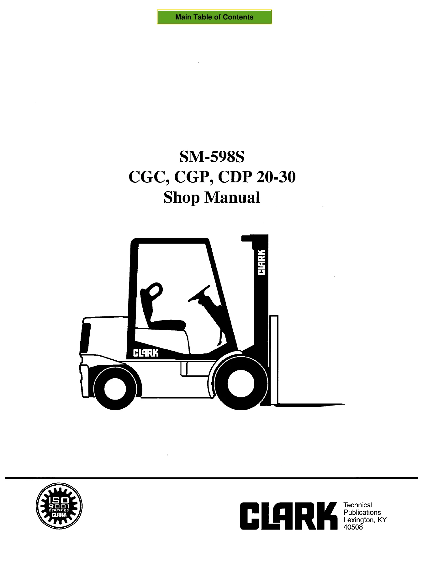
Clark CGC CGP CDP 20-30 Forklift Shop Manual - Service, Repair & Specifications PDF β€” PDF page 1 preview
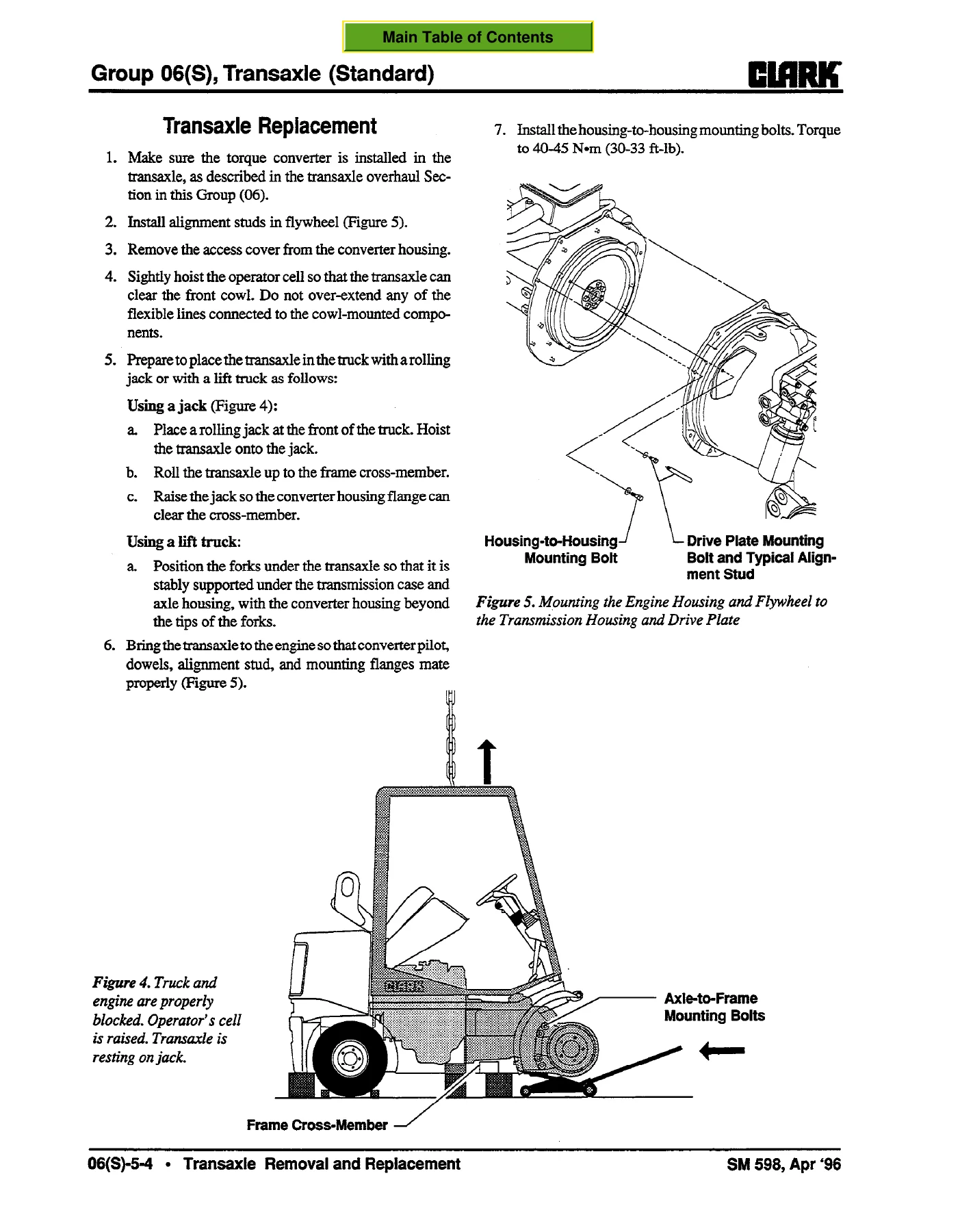
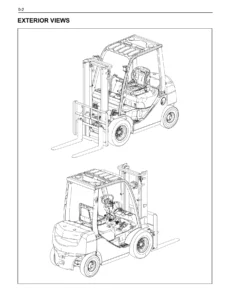
Clark CGC CGP CDP 20-30 Forklift Shop Manual - Service, Repair & Specifications PDF β€” PDF page 473 preview
Clark CGC CGP CDP 20-30 Forklift Shop Manual - Service, Repair & Specifications PDF β€” PDF page 853 preview

After purchase, the manual is delivered as an instant PDF download. There is no physical book and no shipping delay. You can open the file on a computer, tablet or phone and print the pages you need for workshop use.
Reviews

There are no reviews yet.

Be the first to review “Clark CGC CGP CDP 20-30 Forklift Shop Manual – Service, Repair & Specifications PDF”

What Our Customers Say

β˜…β˜…β˜…β˜…β˜… Live reviews from customers
Loading customer reviews...
0
    0
    Your Cart
    Your cart is emptyReturn to Shop
    πŸ›’
    Recently Purchased
    πŸ•’ verified order