
Clark SF35-45D/L CMP40-50sD/L Forklift Service Manual SM-704 PDF
Original price was: $49.95.$29.95Current price is: $29.95.
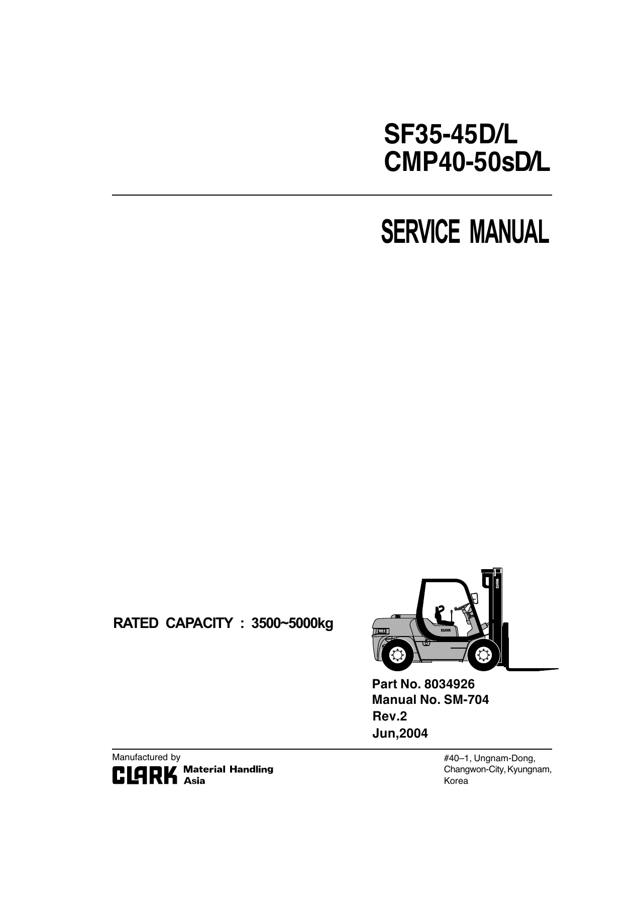
Complete service and repair manual for Clark SF35-45D/L and CMP40-50sD/L forklifts, covering diesel and LPG configurations, specifications, engine service, powershift transmission and drive axle, steering, brakes, hydraulics, mast systems, maintenance, troubleshooting, and hydraulic/electrical circuit diagrams. Manual No. SM-704, Rev.2, June 2004, 1038 pages.
Description
Clark SF35-45D/L CMP40-50sD/L Forklift Service Manual SM-704 PDF
The Clark SF35-45D/L CMP40-50sD/L Forklift Service Manual SM-704 PDF is an extensive workshop reference for the SF35D, SF40D, SF45D, SF35L, SF40L, SF45L and corresponding CMP40D, CMP45D, CMP50sD, CMP40L, CMP45L and CMP50sL forklift configurations. The manual is built around repair and maintenance work carried out in a service workshop, combining machine specifications, component overhaul procedures, adjustment data, troubleshooting information, maintenance schedules and circuit diagrams in one 1038-page document.
Coverage extends well beyond routine servicing. Major sections deal with diesel and LPG engines, the powershift power train and drive axle, load-sensing steering, hydraulic-over-hydraulic brakes, pumps and control valves, lift and tilt cylinders, standard and full-free-lift mast assemblies, carriage and fork inspection, and electrical and hydraulic circuits. Detailed illustrations accompany many dismantling, inspection, measurement and assembly procedures.
File Details
- Manual type: Service Manual
- Brand: Clark
- Models: SF35-45D/L and CMP40-50sD/L
- Rated capacity: 3500~5000kg
- Manual number: SM-704
- Part number: 8034926
- Revision: Rev.2
- Date: Jun, 2004
- Language: English
- Page count: 1038 pages
- File format: PDF
Machine Coverage and Workshop Information
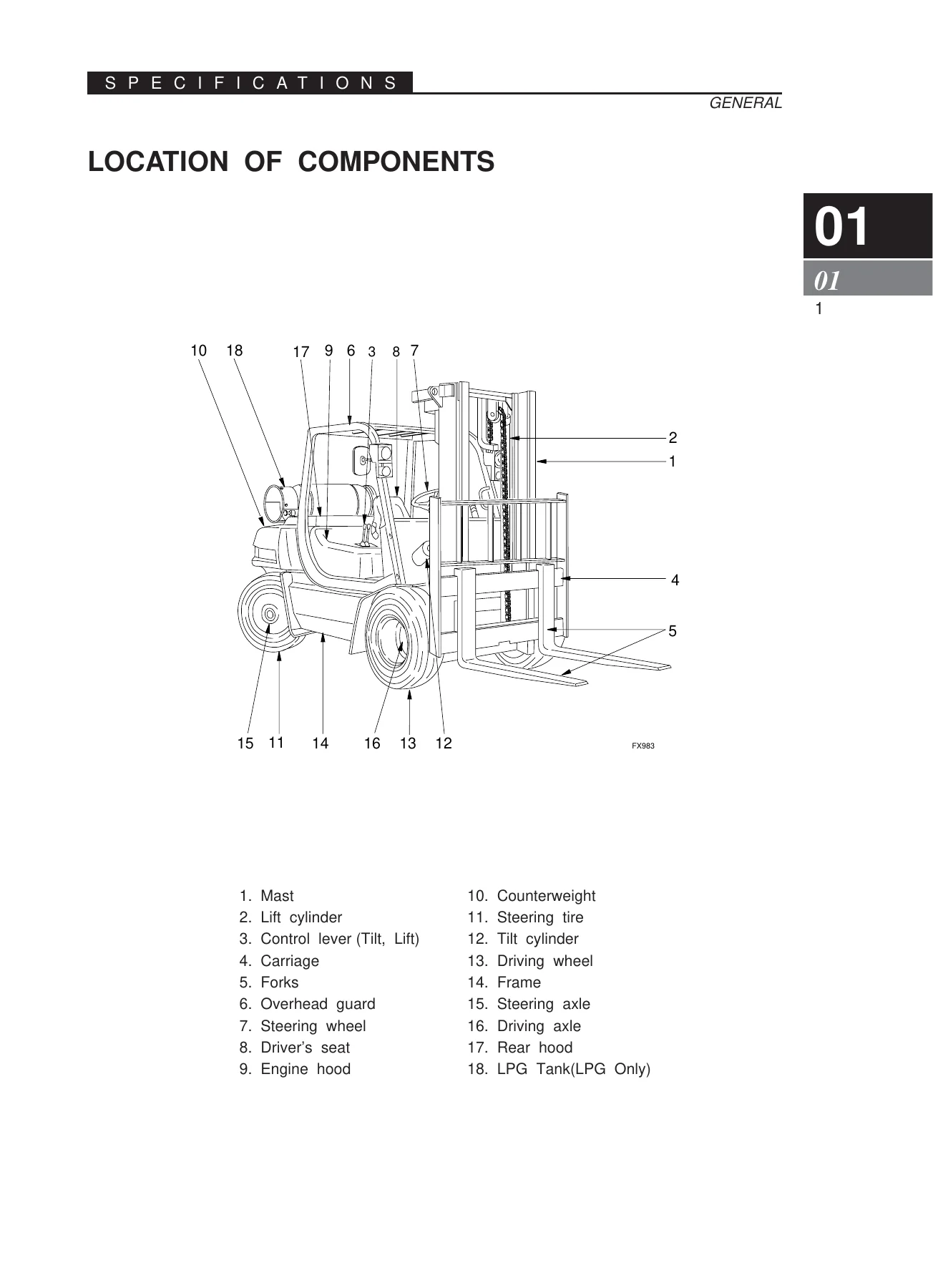
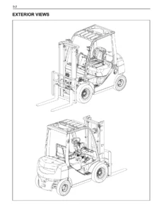
The opening specification material identifies major components and controls, including the mast, lift and tilt cylinders, carriage, forks, steering and driving axles, operator controls, powershift transmission controls and instrument panel. Dimension, weight and performance tables distinguish the diesel and LPG model families and include information for single- and dual-tire configurations where applicable.
Capacity charts are provided for the listed models and mast arrangements, with guidance on the relationship between load center, allowable load and stability. The specifications section also contains coolant, fuel and lubrication charts, periodic maintenance requirements and machine-specific tightening torque data. Maintenance schedules cover engine, chassis and attachment inspections along with lubrication, cleaning and replacement intervals for oils, filters, coolant, brake fluid and other service items.
Diesel and LPG Engine Service
Engine coverage is unusually substantial for a forklift service manual. Separate material is included for Perkins 1004-4, Perkins 1004-42 and Perkins 1104C-44 diesel engines, together with GM V6 LPG engine information. Depending on the engine section, the manual supplies specifications, overhaul dimensions, service limits, tightening values and illustrated procedures for major internal assemblies.
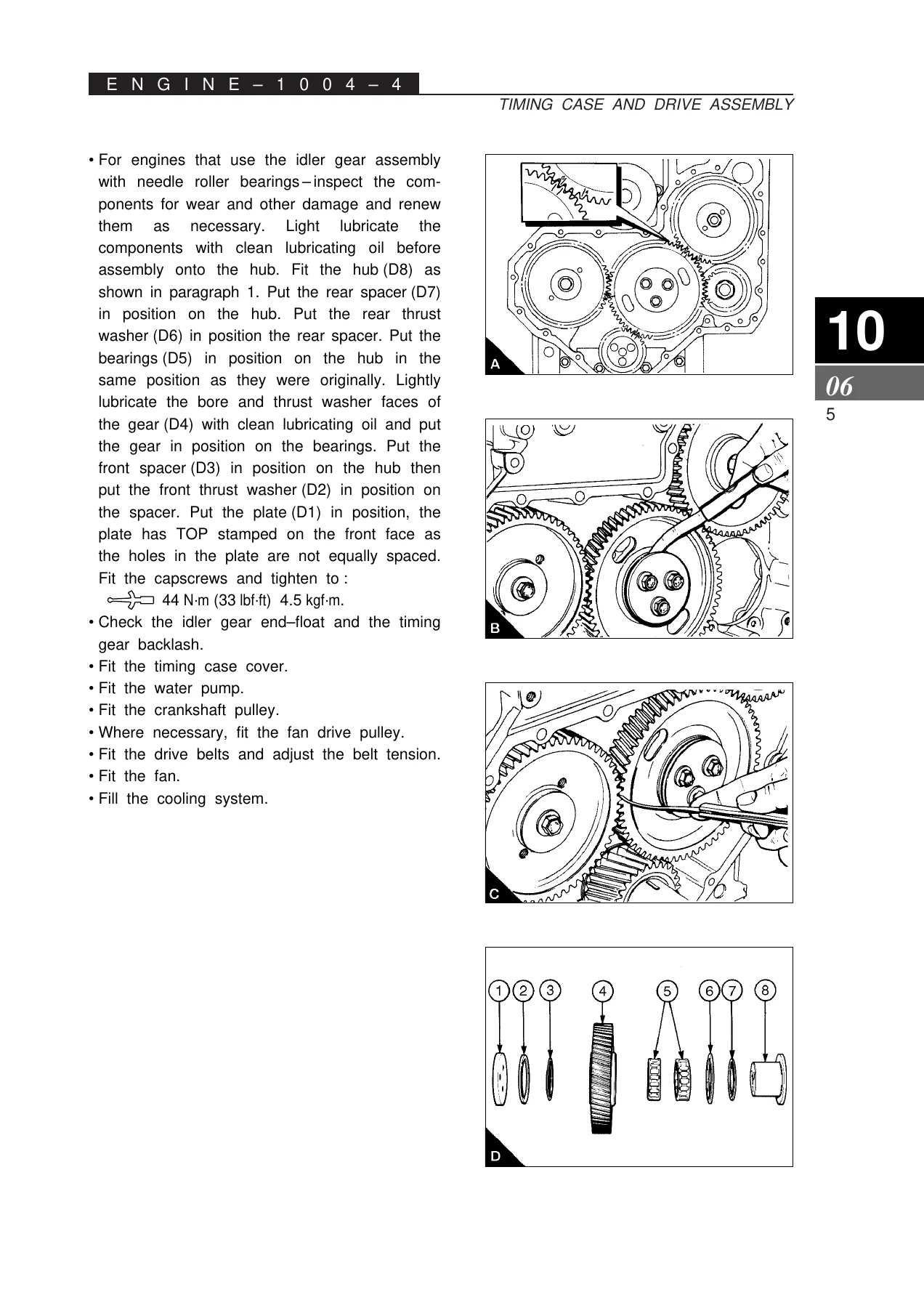
The Perkins engine chapters address cylinder heads, valves and guides, pistons, piston rings and connecting rods, crankshafts and main bearings, timing cases and gear trains, cylinder blocks, engine timing, lubrication, fuel injection, cooling, flywheel housings and electrical equipment. Procedures include inspection, removal, dismantling, measurement, correction, assembly and installation operations. The 1104C-44 material additionally includes aspiration, auxiliary equipment and dedicated special-tool information.
For LPG-equipped trucks, the GM V6 section covers engine removal and replacement, 4.3 liter V6 repair procedures, cooling-system work and MI-4 LP fuel-system information. This makes the Clark SF35-45D/L CMP40-50sD/L service manual useful for both diesel and LPG variants rather than limiting the workshop information to the chassis alone.
Chapters Covered
- 00 – General
- Revision history and foreword
- Safety precautions and preparations for work
- Measurement conversions and standard tightening torque
- 01 – Specifications
- General component locations, instrument panel, dimensions and weight
- Load capacity and capacity charts
- Coolant, fuel and lubrication data
- Periodic maintenance and lubrication
- Machine tightening torque
- 10 – Engine 1004-4, Diesel
- General information and specifications
- Cylinder head, pistons and connecting rods
- Crankshaft, timing case and cylinder block
- Engine timing, lubrication and fuel systems
- Cooling, flywheel, electrical equipment and special tools
- Preventive maintenance
- 12 – Engine 1004-42, Diesel
- General information and specifications
- Cylinder head, pistons, connecting rods and crankshaft
- Timing case, cylinder block and engine timing
- Lubrication, fuel and cooling systems
- Flywheel, electrical equipment, special tools and preventive maintenance
- 13 – Engine 1104C-44, Diesel
- General information and specifications
- Cylinder head, pistons, connecting rods and crankshaft
- Timing case, cylinder block and engine timing
- Aspiration, lubrication, fuel and cooling systems
- Flywheel and housing, electrical and auxiliary equipment
- Special tools
- 15 – Engine GM V6, LPG
- Engine removal and replacement
- 4.3 liter V6 engine repair procedures
- Cooling system
- MI-4 LP fuel system – Tier 2
- 20 – Power Train
- General information and operating principles
- Drive axle
- Powershift transmission
- 30 – Steering System
- Function, maintenance and troubleshooting
- Steering unit
- Priority valve
- 40 – Brake System
- General system information
- Adjustments and brake bleeding
- Removal and installation
- Brake valve
- 50 – Hydraulic System
- Main pump for diesel models
- Auxiliary pump for diesel models
- Main control valve
- Hydraulic cylinders
- W Series hydraulic gear pump for LPG models
- 60 – Mast Maintenance
- Standard, full-free-lift and three-stage mast service
- Mast and carriage inspection, roller clearances and shimming
- Carriage, forks, chains and related components
- 70 – Other Maintenance
- Counterweight removal and installation
- Lifting, jacking and blocking procedures
- 80 – Hydraulic and Electric Circuit Diagrams
- Perkins diesel electrical circuits
- GM V6 LPG electrical circuits
- Diesel and LPG hydraulic circuits
- Tier 2 diesel, LPG and LPG SECM electrical circuits
Taken as a whole, these sections give technicians a system-by-system path from specification and diagnosis through dismantling, inspection, adjustment and reassembly. The manual provides the supporting values needed during those jobs, including clearances, pressures, service limits, capacities, tightening torques and adjustment procedures where specified.
Power Train, Steering and Brake Repair
The power-train section explains the torque converter, powershift transmission, differential, axle shafts, reduction gears, final drives and braking components before moving into service procedures. The powershift unit uses hydraulically actuated clutch packs and the manual includes disassembly, inspection and reassembly information for the drive axle and transmission rather than treating the transaxle as a sealed assembly.
The steering chapter explains the load-sensing hydraulic steering arrangement and follows it with pressure checks, adjustment information and troubleshooting tables. Fault conditions addressed include heavy steering, abnormal steering-wheel behavior, slow response, kick-back, leakage and other hydraulic or mechanical causes. Separate steering-unit and priority-valve sections provide dismantling and assembly guidance.
Brake-system material covers the hydraulic-over-hydraulic arrangement, adjustment, system bleeding, removal and installation procedures and brake-valve service. This is accompanied by the torque, pressure and adjustment information required to return serviced components to the specified condition.
Hydraulic System and Mast Work
For hydraulic repairs, the Clark SF35-45D/L CMP40-50sD/L Forklift Service Manual SM-704 PDF includes pump specifications and overhaul information, auxiliary-pump troubleshooting, main-control-valve construction and fault diagnosis, and lift/tilt cylinder service. The main-control-valve material addresses problems such as sticking spools, leakage, cylinder drift and relief-valve or pump faults.
Mast maintenance includes inspection of rails, rollers, chains, cylinders, carriage and forks. Procedures cover removal and installation of the mast, trunnion checks, roller-clearance measurements, shim selection and adjustment, standard two-stage masts, full-free-lift two-stage masts and full-free-lift three-stage arrangements. Carriage and fork sections include wear, alignment, fatigue and bending checks. Flow-limiting and flow-regulating valve operation is also described as part of the mast hydraulic system.
Electrical and Hydraulic Circuit Reference
The final circuit section provides dedicated diagrams for diesel and LPG configurations. Electrical diagrams include Perkins 1004-42 and GM V6 non-Tier 2 arrangements plus Tier 2 diesel, LPG and LPG SECM configurations. Hydraulic circuit coverage is provided for diesel and LPG trucks. These diagrams help trace connections between components during electrical diagnosis and hydraulic-system troubleshooting.
Repair Your Clark Forklift with the Correct Procedures and Specifications
This manual supports a wide range of workshop jobs, from routine fluid and filter service through brake bleeding, steering diagnosis, hydraulic pump and valve repair, mast adjustment, powershift transmission and axle work, and major diesel or LPG engine repairs. Having the correct sequences, service limits, pressure settings, clearances and tightening values available is especially important when components are being dismantled and returned to service.
IMAGES PREVIEW
The Clark SF35-45D/L CMP40-50sD/L Forklift Service Manual SM-704 PDF is supplied as an instant PDF download after payment. There is no physical book and no shipping delay. Open it on a computer, tablet or phone, keep it available in the workshop, and print the pages needed for the repair at hand.
Reviews
There are no reviews yet.