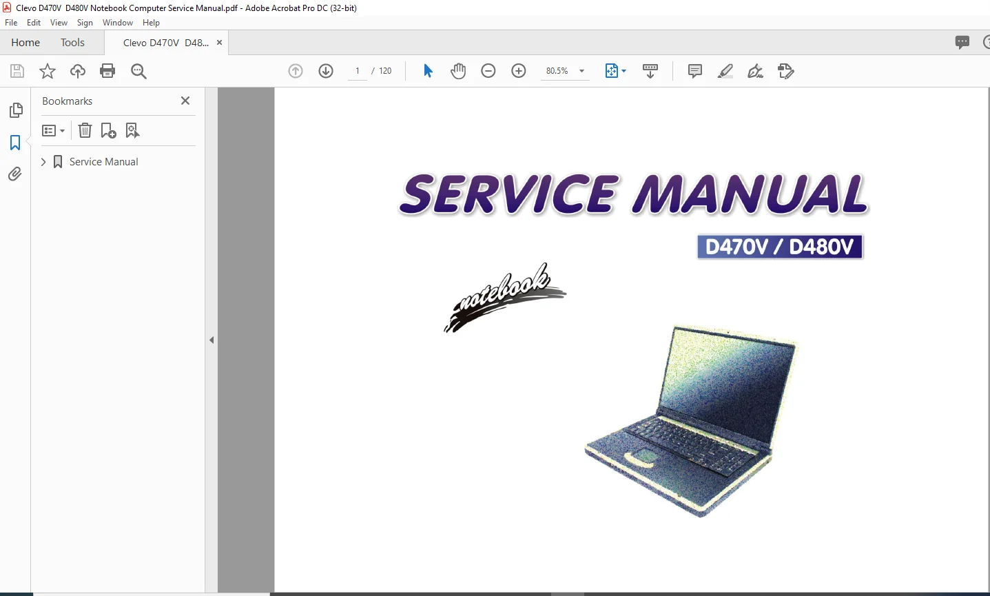
Clevo D470V D480V Notebook Computer Service Manual – PDF DOWNLOAD
Clevo D470V D480V Notebook Computer Service Manual – PDF DOWNLOADClevo D470V D480V Notebook Computer Service Manual – PDF DOWNLOAD
Preface
Notice
The company reserves the right to revise this publication or to change its contents without notice. Information contained herein is for reference only and does not constitute a commitment on the part of the manufacturer or any subsequent vendor.
They assume no responsibility or liability for any errors or inaccuracies that may appear in this publication nor are they in anyway responsible for any loss or damage resulting from the use (or misuse) of this publication.
This publication and any accompanying software may not, in whole or in part, be reproduced, translated, transmitted or reduced to any machine readable form without prior consent from the vendor, manufacturer or creators of this publication, except for copies kept by the user for backup purposes.
Brand and product names mentioned in this publication may or may not be copyrights and/or registered trademarks of their respective companies. They are mentioned for identification purposes only and are not intended as an endorsement of that product or its manufacturer
Clevo D470V D480V Notebook Computer Service Manual – PDF DOWNLOAD
Service Manual.......................................................  1
	Preface..........................................................  4
		Trademarks...................................................  4
		About this Manual............................................  5
		IMPORTANT SAFETY INSTRUCTIONS................................  6
			CAUTION..................................................  6
		Instructions for Care and Operation..........................  7
		Power Safety.................................................  8
		Battery Precautions..........................................  9
			Related Documents........................................ 10
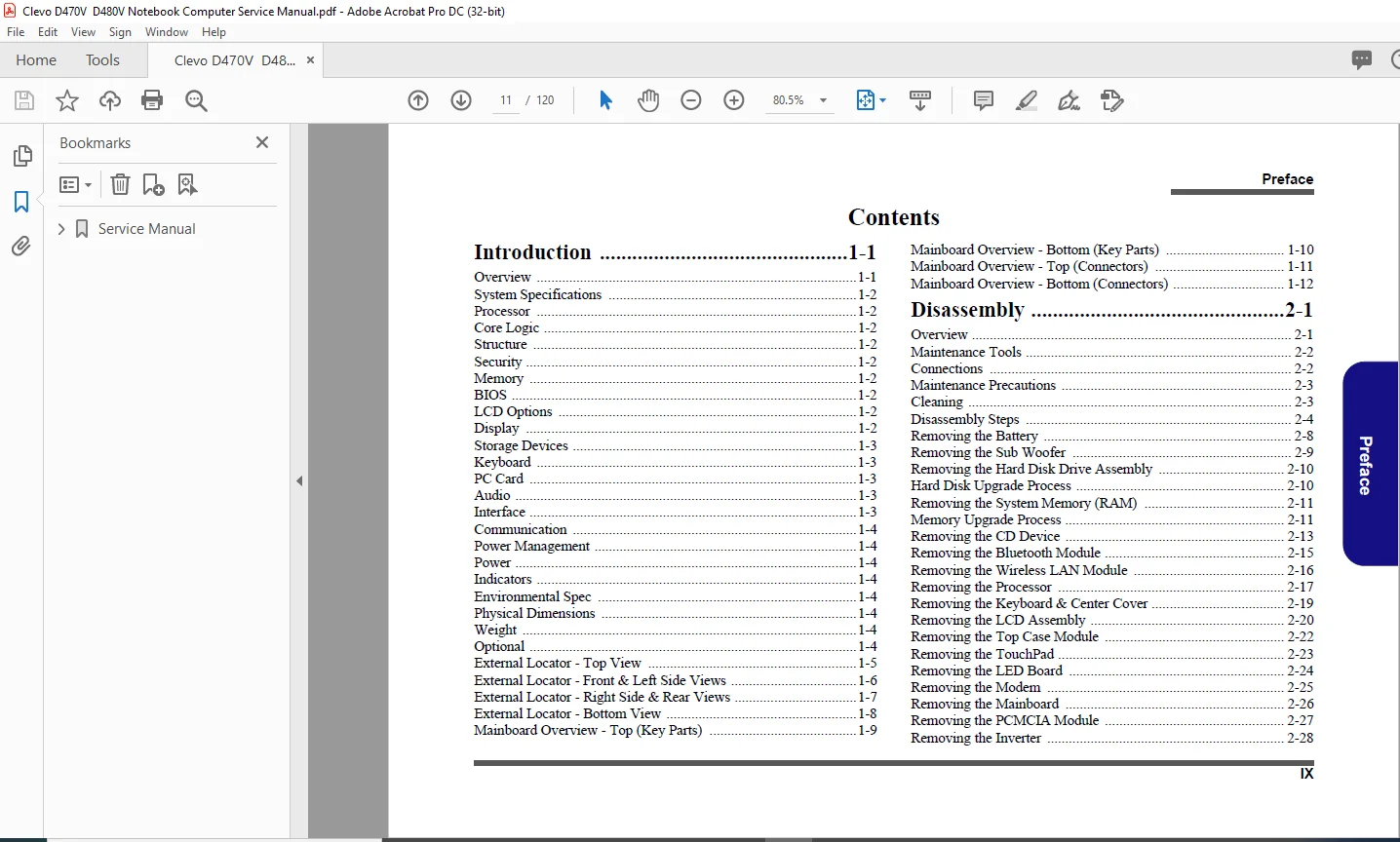
		Introduction 1-1............................................. 11
		Disassembly 2-1.............................................. 11
	1: Introduction.................................................. 15
		Overview..................................................... 15
		System Specifications........................................ 16
		External Locator - Top View.................................. 19
		External Locator - Front & Left Side Views................... 20
		External Locator - Right Side & Rear Views................... 21
		External Locator - Bottom View............................... 22
		Mainboard Overview - Top (Key Parts)......................... 23
		Mainboard Overview - Bottom (Key Parts)...................... 24
		Mainboard Overview - Top (Connectors)........................ 25
		Mainboard Overview - Bottom (Connectors)..................... 26
	2: Disassembly................................................... 27
		Overview..................................................... 27
		Maintenance Tools............................................ 28
		Connections.................................................. 28
		Maintenance Precautions...................................... 29
			Cleaning................................................. 29
		Disassembly Steps............................................ 30
			To remove the Battery:................................... 30
				1. Remove the battery page 2 - 8..................... 30
			To remove the HDD Assembly:.............................. 30
				1. Remove the battery page 2 - 8..................... 30
				2. Remove the HDD assembly page 2 - 9................ 30
			To remove the System Memory:............................. 30
				1. Remove the battery page 2 - 8..................... 30
				2. Remove the system memory page 2 - 10.............. 30
			To remove the CD Device:................................. 30
				1. Remove the battery page 2 - 8..................... 30
				2. Remove the CD device page 2 - 12.................. 30
			To remove the Bluetooth Module:.......................... 30
				1. Remove the battery page 2 - 8..................... 30
				2. Remove the Bluetooth module page 2 - 14........... 30
			To remove the Wireless LAN Module:....................... 30
				1. Remove the battery page 2 - 8..................... 30
				2. Remove the Wireless LAN module page 2 - 15........ 30
			To remove the Processor:................................. 30
				1. Remove the battery page 2 - 8..................... 30
				2. Remove the processor page 2 - 16.................. 30
			To remove the Keyboard & Center Cover:................... 30
				1. Remove the battery page 2 - 8..................... 30
				2. Remove the keyboard & center cover page 2 - 18.... 30
			To remove the LCD Assembly:.............................. 30
				1. Remove the battery page 2 - 8..................... 30
				2. Remove the HDD page 2 - 9......................... 30
				3. Remove the system memory page 2 - 10.............. 30
				4. Remove the CD device page 2 - 12.................. 30
				5. Remove the Bluetooth module page 2 - 14........... 30
				6. Remove the Wireless LAN module page 2 - 15........ 30
				7. Remove the processor page 2 - 16.................. 30
				8. Remove the keyboard & center cover page 2 - 18.... 30
				9. Remove the LCD assembly page 2 - 19............... 30
			To remove the Top Case Module:........................... 31
				1. Remove the battery page 2 - 8..................... 31
				2. Remove the HDD page 2 - 9......................... 31
				3. Remove the system memory page 2 - 10.............. 31
				4. Remove the CD device page 2 - 12.................. 31
				5. Remove the Bluetooth module page 2 - 14........... 31
				6. Remove the Wireless LAN module page 2 - 15........ 31
				7. Remove the processor page 2 - 16.................. 31
				8. Remove the keyboard & center cover page 2 - 18.... 31
				9. Remove the LCD assembly page 2 - 19............... 31
				10. Remove the top case module page 2 - 21........... 31
			To remove the TouchPad:.................................. 31
				1. Remove the battery page 2 - 8..................... 31
				2. Remove the HDD page 2 - 9......................... 31
				3. Remove the system memory page 2 - 10.............. 31
				4. Remove the CD device page 2 - 12.................. 31
				5. Remove the Bluetooth module page 2 - 14........... 31
				6. Remove the Wireless LAN module page 2 - 15........ 31
				7. Remove the processor page 2 - 16.................. 31
				8. Remove the keyboard & center cover page 2 - 18.... 31
				9. Remove the LCD assembly page 2 - 19............... 31
				10. Remove the top case module page 2 - 21........... 31
				11. Remove the TouchPad page 2 - 22.................. 31
			To remove the LED board:................................. 31
				1. Remove the battery page 2 - 8..................... 31
				2. Remove the HDD page 2 - 9......................... 31
				3. Remove the system memory page 2 - 10.............. 31
				4. Remove the CD device page 2 - 12.................. 31
				5. Remove the Bluetooth module page 2 - 14........... 31
				6. Remove the Wireless LAN module page 2 - 15........ 31
				7. Remove the processor page 2 - 16.................. 31
				8. Remove the keyboard & center cover page 2 - 18.... 31
				9. Remove the LCD assembly page 2 - 19............... 31
				10. Remove the top case module page 2 - 21........... 31
				11. Remove the LED board page 2 - 23................. 31
			To remove the Modem:..................................... 31
				1. Remove the battery page 2 - 8..................... 31
				2. Remove the HDD page 2 - 9......................... 31
				3. Remove the system memory page 2 - 10.............. 31
				4. Remove the CD device page 2 - 12.................. 31
				5. Remove the Bluetooth module page 2 - 14........... 31
				6. Remove the Wireless LAN module page 2 - 15........ 31
				7. Remove the processor page 2 - 16.................. 31
				8. Remove the keyboard & center cover page 2 - 18.... 31
				9. Remove the LCD assembly page 2 - 19............... 31
				10. Remove the top case module page 2 - 21........... 31
				11. Remove the modem page 2 - 24..................... 31
			To remove the Mainboard:................................. 32
				1. Remove the battery page 2 - 8..................... 32
				2. Remove the HDD page 2 - 9......................... 32
				3. Remove the system memory page 2 - 10.............. 32
				4. Remove the CD Device page 2 - 12.................. 32
				5. Remove the Bluetooth module page 2 - 14........... 32
				6. Remove the Wireless LAN module page 2 - 15........ 32
				7. Remove the processor page 2 - 16.................. 32
				8. Remove the keyboard & center cover page 2 - 18.... 32
				9. Remove the LCD assembly page 2 - 19............... 32
				10. Remove the top case module page 2 - 21........... 32
				11. Remove the modem page 2 - 24..................... 32
				12. Remove the mainboard page 2 - 25................. 32
			To remove the Sub Woofer:................................ 32
				1. Remove the battery page 2 - 8..................... 32
				2. Remove the HDD page 2 - 9......................... 32
				3. Remove the system memory page 2 - 10.............. 32
				4. Remove the CD Device page 2 - 12.................. 32
				5. Remove the Bluetooth module page 2 - 14........... 32
				6. Remove the Wireless LAN module page 2 - 15........ 32
				7. Remove the processor page 2 - 16.................. 32
				8. Remove the keyboard & center cover page 2 - 18.... 32
				9. Remove the LCD assembly page 2 - 19............... 32
				10. Remove the top case module page 2 - 21........... 32
				11. Remove the modem page 2 - 24..................... 32
				12. Remove the mainboard page 2 - 25................. 32
				13. Remove the sub woofer page 2 - 26................ 32
			To remove the Card Reader:............................... 32
				1. Remove the battery page 2 - 8..................... 32
				2. Remove the HDD page 2 - 9......................... 32
				3. Remove the system memory page 2 - 10.............. 32
				4. Remove the CD Device page 2 - 12.................. 32
				5. Remove the Bluetooth module page 2 - 14........... 32
				6. Remove the Wireless LAN module page 2 - 15........ 32
				7. Remove the processor page 2 - 16.................. 32
				8. Remove the keyboard & center cover page 2 - 18.... 32
				9. Remove the LCD assembly page 2 - 19............... 32
				10. Remove the top case module page 2 - 21........... 32
				11. Remove the modem page 2 - 24..................... 32
				12. Remove the mainboard page 2 - 25................. 32
				13. Remove the card reader page 2 - 27............... 32
			To remove the PCMCIA Module:............................. 32
				1. Remove the battery page 2 - 8..................... 32
				2. Remove the HDD page 2 - 9......................... 32
				3. Remove the system memory page 2 - 10.............. 32
				4. Remove the CD Device page 2 - 12.................. 32
				5. Remove the Bluetooth module page 2 - 14........... 32
				6. Remove the Wireless LAN module page 2 - 15........ 32
				7. Remove the processor page 2 - 16.................. 32
				8. Remove the keyboard & center cover page 2 - 18.... 32
				9. Remove the LCD assembly page 2 - 19............... 32
				10. Remove the top case module page 2 - 21........... 32
				11. Remove the modem page 2 - 24..................... 32
				12. Remove the mainboard page 2 - 25................. 32
				13. Remove the PCMCIA module page 2 - 28............. 32
			To remove the Inverter:.................................. 33
				1. Remove the battery page 2 - 8..................... 33
				2. Remove the HDD page 2 - 9......................... 33
				3. Remove the system memory page 2 - 10.............. 33
				4. Remove the CD Device page 2 - 12.................. 33
				5. Remove the Bluetooth module page 2 - 14........... 33
				6. Remove the Wireless LAN module page 2 - 15........ 33
				7. Remove the processor page 2 - 16.................. 33
				8. Remove the keyboard & center cover page 2 - 18.... 33
				9. Remove the LCD assembly page 2 - 19............... 33
				10. Remove the top case module page 2 - 21........... 33
				11. Remove the inverter page 2 - 29.................. 33
			To remove the LCD Panel:................................. 33
				1. Remove the battery page 2 - 8..................... 33
				2. Remove the HDD page 2 - 9......................... 33
				3. Remove the system memory page 2 - 10.............. 33
				4. Remove the CD Device page 2 - 12.................. 33
				5. Remove the Bluetooth module page 2 - 14........... 33
				6. Remove the Wireless LAN module page 2 - 15........ 33
				7. Remove the processor page 2 - 16.................. 33
				8. Remove the keyboard & center cover page 2 - 18.... 33
				9. Remove the LCD assembly page 2 - 19............... 33
				10. Remove the top case module page 2 - 21........... 33
				11. Remove the inverter page 2 - 29.................. 33
				12. Remove the LCD panel page 2 - 30................. 33
			To remove the Camera Module:............................. 33
				1. Remove the battery page 2 - 8..................... 33
				2. Remove the HDD page 2 - 9......................... 33
				3. Remove the system memory page 2 - 10.............. 33
				4. Remove the CD device page 2 - 12.................. 33
				5. Remove the Bluetooth module page 2 - 14........... 33
				6. Remove the Wireless LAN module page 2 - 15........ 33
				7. Remove the processor page 2 - 16.................. 33
				8. Remove the keyboard & center cover page 2 - 18.... 33
				9. Remove the LCD assembly page 2 - 19............... 33
				10. Remove the top case module page 2 - 21........... 33
				11. Remove the inverter page 2 - 29.................. 33
				12. Remove the LCD panel page 2 - 30................. 33
				13. Remove the camera module page 2 - 31............. 33
			To remove the Bluetooth & WLAN Antennas:................. 33
				1. Remove the battery page 2 - 8..................... 33
				2. Remove the HDD page 2 - 9......................... 33
				3. Remove the system memory page 2 - 10.............. 33
				4. Remove the CD device page 2 - 12.................. 33
				5. Remove the Bluetooth module page 2 - 14........... 33
				6. Remove the Wireless LAN module page 2 - 15........ 33
				7. Remove the processor page 2 - 16.................. 33
				8. Remove the keyboard & center cover page 2 - 18.... 33
				9. Remove the LCD assembly page 2 - 19............... 33
				10. Remove the top case module page 2 - 21........... 33
				11. Remove the inverter page 2 - 29.................. 33
				12. Remove the LCD panel page 2 - 30................. 33
				13. Remove the antennas page 2 - 32.................. 33
		Removing the Battery......................................... 34
			1........................................................ 34
			3........................................................ 34
			4........................................................ 34
			5........................................................ 34
			6........................................................ 34
		Removing the Hard Disk Drive Assembly........................ 35
		Hard Disk Upgrade Process.................................... 35
			1........................................................ 35
			4........................................................ 35
			5........................................................ 35
			6........................................................ 35
			7........................................................ 35
		Removing the System Memory (RAM)............................. 36
		Memory Upgrade Process....................................... 36
			1........................................................ 36
			8........................................................ 36
			9........................................................ 36
			10....................................................... 36
			1........................................................ 37
			2........................................................ 37
			3........................................................ 37
			3........................................................ 37
		Removing the CD Device....................................... 38
			1........................................................ 38
			8........................................................ 38
			9........................................................ 38
			10....................................................... 38
			9........................................................ 38
				1.................................................... 39
				2.................................................... 39
		Removing the Bluetooth Module................................ 40
			1........................................................ 40
			2........................................................ 40
			3........................................................ 40
			4........................................................ 40
			7........................................................ 40
			8........................................................ 40
			9........................................................ 40
			10....................................................... 40
		Removing the Wireless LAN Module............................. 41
			1........................................................ 41
			8........................................................ 41
			9........................................................ 41
			10....................................................... 41
			11....................................................... 41
			12....................................................... 41
			13....................................................... 41
			14....................................................... 41
			15....................................................... 41
			9........................................................ 41
		Removing the Processor....................................... 42
			1........................................................ 42
			7........................................................ 42
			9........................................................ 42
			10....................................................... 42
			11....................................................... 42
			14....................................................... 42
			15....................................................... 42
			11....................................................... 42
				1.................................................... 43
				2.................................................... 43
				3.................................................... 43
				4.................................................... 43
				5.................................................... 43
		Removing the Keyboard & Center Cover......................... 44
			1........................................................ 44
			4........................................................ 44
			5........................................................ 44
			6........................................................ 44
			7........................................................ 44
			18....................................................... 44
			19....................................................... 44
			20....................................................... 44
		Removing the LCD Assembly.................................... 45
			1........................................................ 45
			13....................................................... 45
			14....................................................... 45
			17....................................................... 45
			11....................................................... 45
				1.................................................... 46
				2.................................................... 46
				3.................................................... 46
				4.................................................... 46
		Removing the Top Case Module................................. 47
			1........................................................ 47
			4........................................................ 47
			5........................................................ 47
			8........................................................ 47
			9........................................................ 47
			10....................................................... 47
		Removing the TouchPad........................................ 48
			1........................................................ 48
			8........................................................ 48
			9........................................................ 48
			10....................................................... 48
			11....................................................... 48
			12....................................................... 48
			13....................................................... 48
			14....................................................... 48
		Removing the LED Board....................................... 49
			1........................................................ 49
			2........................................................ 49
			3........................................................ 49
		Removing the Modem........................................... 50
			1........................................................ 50
			2........................................................ 50
			3........................................................ 50
			4........................................................ 50
			11....................................................... 50
		Removing the Mainboard....................................... 51
			1........................................................ 51
			8........................................................ 51
			9........................................................ 51
			10....................................................... 51
			11....................................................... 51
		Removing the Sub Woofer...................................... 52
			1........................................................ 52
			4........................................................ 52
			5........................................................ 52
		Removing the Card Reader Assembly............................ 53
			1........................................................ 53
			2........................................................ 53
			3........................................................ 53
		Removing the PCMCIA Module................................... 54
			1........................................................ 54
			2........................................................ 54
			3........................................................ 54
		Removing the Inverter........................................ 55
			1........................................................ 55
			6........................................................ 55
			7........................................................ 55
			8........................................................ 55
			9........................................................ 55
			10....................................................... 55
			11....................................................... 55
		Removing the LCD Panel....................................... 56
			1........................................................ 56
			8........................................................ 56
			9........................................................ 56
			11....................................................... 56
			10....................................................... 56
			12....................................................... 56
			19....................................................... 56
			20....................................................... 56
		Removing the Camera Module................................... 57
			1........................................................ 57
			2........................................................ 57
		Removing the Bluetooth/WLAN Antennas......................... 58
			1........................................................ 58
			2........................................................ 58
			3........................................................ 58
			4........................................................ 58
			5........................................................ 58
			6........................................................ 58
	Appendix A: Part Lists........................................... 59
		Part List Illustration Location.............................. 60
		Top (D470V).................................................. 61
			Figure 1 Top (D470V)..................................... 61
		Bottom (D470V)............................................... 62
			Figure 2 Bottom (D470V).................................. 62
		LCD 17" (D470V).............................................. 63
			Figure 3 LCD 17" (D470V)................................. 63
		CD-ROM Drive (D470V)......................................... 64
			Figure 4 CD-ROM Drive (D470V)............................ 64
		CD-RW Drive (D470V).......................................... 65
			Figure 5 CD-RW Drive (D470V)............................. 65
		DVD-ROM Drive (D470V)........................................ 66
			Figure 6 DVD-ROM Drive (D470V)........................... 66
		Combo Drive (D470V).......................................... 67
			Figure 7 Combo Drive (D470V)............................. 67
		Hard Disk Drive (D470V)...................................... 68
			Figure 8 HDD Drive (D470V)............................... 68
		Top (D480V).................................................. 69
			Figure 9 Top (D480V)..................................... 69
		Bottom (D480V)............................................... 70
			Figure 10 Bottom (D480V)................................. 70
		LCD 17" (D480V).............................................. 71
			Figure 11 LCD 17" (D480V)................................ 71
		CD-ROM Drive (D480V)......................................... 72
			Figure 12 CD-ROM Drive (D480V)........................... 72
		CD-RW Drive (D480V).......................................... 73
			Figure 13 CD-RW Drive (D480V)............................ 73
		DVD-ROM Drive (D480V)........................................ 74
			Figure 14 DVD-ROM Drive (D480V).......................... 74
		Combo Drive (D480V).......................................... 75
			Figure 15 Combo Drive (D480V)............................ 75
		Hard Disk Drive (D480V)...................................... 76
			Figure 16 HDD Drive (D480V).............................. 76
	Appendix B: Schematic Diagrams................................... 77
		System Block Diagram......................................... 78
			Sheet 1 of 42 System Block Diagram....................... 78
		Socket 478 1 of 2............................................ 79
			Sheet 2 of 42 Socket 478 1 of 2.......................... 79
		Socket 478 & ITP 2 of 2...................................... 80
			Sheet 3 of 42 Socket 478 & ITP 2 of 2.................... 80
		Clock Generator.............................................. 81
			Sheet 4 of 42 Clock Generator............................ 81
		M648FX-1 (Host/AGP) 1 of 4................................... 82
			Sheet 5 of 42 M648FX-1 (Host/AGP) 1 of 4................. 82
		M648FX-2 (Memory for DDR) 2 of 4............................. 83
			Sheet 6 of 42 M648FX-2 (Memory for DDR) 2 of 4........... 83
		M648FX-3 & CRT Out 3 of 4.................................... 84
			Sheet 7 of 42 M648FX-3 & CRT Out 3 of 4.................. 84
		M648FX-4 (Power) 4 of 4...................................... 85
			Sheet 8 of 42 M648FX-4 (Power) 4 of 4.................... 85
		DDR Memory DIMM.............................................. 86
			Sheet 9 of 42 DDR Memory DIMM............................ 86
		DDR SSTL-2 Termination....................................... 87
			Sheet 10 of 42 DDR SSTL-2 Termination.................... 87
		LVDS Interface (SiS302LV).................................... 88
			Sheet 11 of 42 LVDS interface (SiS302LV)................. 88
		Panel Con & LED Indicator.................................... 89
			Sheet 12 of 42 Panel Con & LED Indicator................. 89
		963-1 (PCI/IDE/HyperZip) 1 of 4.............................. 90
			Sheet 13 of 42 963-1 (PCI/IDE/ HyperZip) 1 of 4.......... 90
		963-2 (Misc Signals) 2 of 4.................................. 91
			Sheet 14 of 42 963-2 (Misc Signals) 2 of 4............... 91
		963-3 (USB I/F) 3 of 4....................................... 92
			Sheet 15 of 42 963-3 (USB I/F) 3 of 4.................... 92
		963-4 (Power & RTC) 4 of 4................................... 93
			Sheet 16 of 42 963-4 (Power & RTC) 4 of 4................ 93
		HDD/Combo Connector.......................................... 94
			Sheet 17 of 42 HDD/Combo Connector....................... 94
		USB Port..................................................... 95
			Sheet 18 of 42 USB Port.................................. 95
		PCMCIA ENE1410............................................... 96
			Sheet 19 of 42 PCMCIA ENE1410............................ 96
		PCMCIA Power & MDC Interface................................. 97
			Sheet 20 of 42 PCMCIA Power & MDC Interface.............. 97
		1394 PHY TSB41LV01........................................... 98
			Sheet 21 of 42 1394 PHY TSB41LV01........................ 98
		LPC Super I/O................................................ 99
			Sheet 22 of 42 LPC Super I/O............................. 99
		LPT/COM Port.................................................100
			Sheet 23 of 42 LPT/COM Port..............................100
		LPC H8.......................................................101
			Sheet 24 of 42 LPC H8....................................101
		LAN RTL8100S(B)-32/RTL8100C..................................102
			Sheet 25 of 42 LAN RTL8100S(B)- 32/RTL8100C..............102
		Audio Codec ALC650...........................................103
			Sheet 26 of 42 Audio Codec ALC650........................103
		Audio Out & Off Board Connectors.............................104
			Sheet 27 of 42 Audio Out & Off Board Connectors..........104
		System Power Control.........................................105
			Sheet 28 of 42 System Power Control......................105
		Fan Control and SpeedStep....................................106
			Sheet 29 of 42 Fan Control & SpeedStep...................106
		Mobility M10-P...............................................107
			Sheet 30 of 42 Mobility M10-P............................107
		Mobility M10-P Mem A/B.......................................108
			Sheet 31 of 42 Mobility M10-P Mem A/B....................108
		VGA DDR DRAM Channel A.......................................109
			Sheet 32 of 42 VGA DDR DRAM Channel A....................109
		VGA DDR DRAM Channel B.......................................110
			Sheet 33 of 42 VGA DDR DRAM Channel B....................110
		VGA DDR DRAM Termination.....................................111
			Sheet 34 of 42 VGA DDR DRAM Termination..................111
		Mobility M10-P Power.........................................112
			Sheet 35 of 42 Mobility M10-P Power......................112
		VCORE........................................................113
			Sheet 36 of 42 VCORE.....................................113
		+1.2V, +1.5V.................................................114
			Sheet 37 of 42 +1.2V, +1.5V..............................114
		+2.5V, +1.25V................................................115
			Sheet 38 of 42 +2.5V, +1.25V.............................115
		+3V, +5V, +12V...............................................116
			Sheet 39 of 42 +3V, +5V, +12V............................116
		Charger......................................................117
			Sheet 40 of 42 Charger...................................117
		S/W Board & Hot Key..........................................118
			Sheet 41 of 42 S/W Board & Hot Key.......................118
		TouchPad & SwitchBoard.......................................119
			Sheet 42 of 42 TouchPad & Switchboard....................119
PLEASE NOTE:
This is the SAME exact manual used by your dealers to fix your vehicle.
The same can be yours in the next 2-3 mins as you will be directed to the download page immediately after paying for the manual.
Any queries / doubts regarding your purchase, please feel free to contact [email protected]
S.M
1 review for Clevo D470V D480V Notebook Computer Service Manual – PDF DOWNLOAD





Eduardo –
Fast; convenient; perfect.