
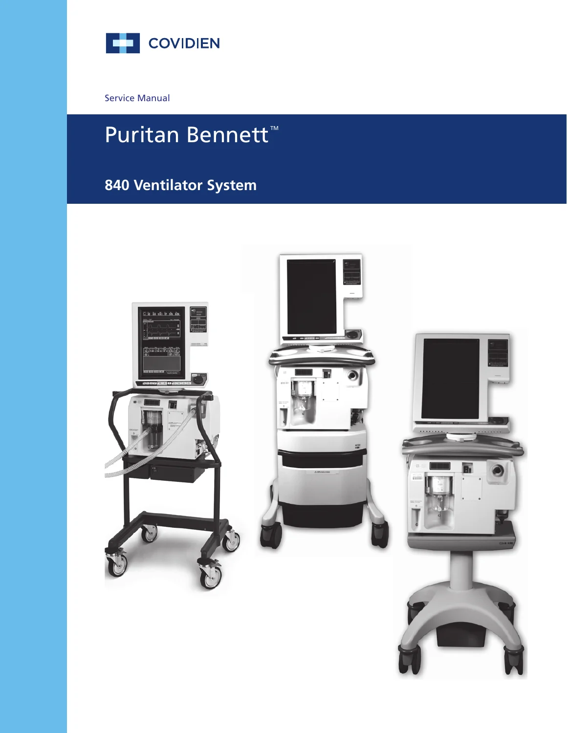
Covidien Puritan Bennett 840 Ventilator System Service Manual 10067703 Rev D
Original price was: $49.95.$29.95Current price is: $29.95.
674-page Covidien Puritan Bennett 840 Ventilator System service manual covering specifications, theory of operation, POST/SST/EST, Service Mode, performance verification, diagnostic codes, alarm handling, component repair, 806 compressor and BPS service, and parts identification.
Description
Covidien Puritan Bennett 840 Ventilator System Service Manual 10067703 Rev D
The Covidien Puritan Bennett 840 Ventilator System Service Manual 10067703 Rev D is a comprehensive service reference for the Puritan Bennett 840 critical-care ventilator. The manual is written for certified biomedical engineering technicians or personnel with equivalent training and experience, and it covers the system from product configuration and operating theory through self-tests, service mode, performance verification, diagnostics, repair procedures, and parts identification. The document also explains the relationship between the breath delivery unit (BDU), graphical user interface (GUI), backup power source (BPS), optional 806 Compressor Unit, patient system, and supported cart configurations.
This service manual is intended to be used together with the Puritan Bennett 800 Series Ventilator System Operator’s and Technical Reference Manual; the manual specifically states that both are needed for field repair. It also notes that the configurations covered were those supported by Covidien at the time of publication and that the information may not be applicable to every individual ventilator configuration. Those points are important when planning service work on a specific installed unit.
File Details
- Manual type: Service Manual
- Brand / system: Puritan Bennett 840 Ventilator System
- Manufacturer: Covidien llc
- Document: Part No. 10067703 Rev.D
- Date: 2014-06
- Language: English
- Page count: 674 pages
- File format: PDF
System Theory, Specifications and Service Data
The Puritan Bennett 840 is described as an electronically controlled, pneumatically powered critical-care ventilator for infant, pediatric, and adult patients. The manual first establishes the system architecture and configuration options, then provides detailed physical, pneumatic, electrical, environmental, communication, and operating information. Coverage includes the BDU and GUI, 802 and 803 backup power sources, the optional 806 compressor, patient circuits, humidification arrangements, RTA and other cart configurations, air and oxygen fittings, controls, indicators, and communication ports.
The specification material is substantial. It includes component weights and dimensions; gas inlet pressure and flow requirements; electrical input configurations; leakage current limits; BPS voltage, capacity, operating time, recharge and storage information; alarm volume; compressor sound level; remote alarm and RS-232 information; pressure and volume measurement ranges; oxygen measurement; patient-circuit pressure-drop data; bacteria filter efficiency; and detailed ranges, resolutions, accuracies, and defaults for ventilator settings, alarm settings, and monitored patient data. Maintenance schedules identify recurring inspections, calibrations, self-tests, filter work, oxygen-sensor replacement, battery attention, and preventive-maintenance intervals.
Pneumatic and Electrical Theory of Operation
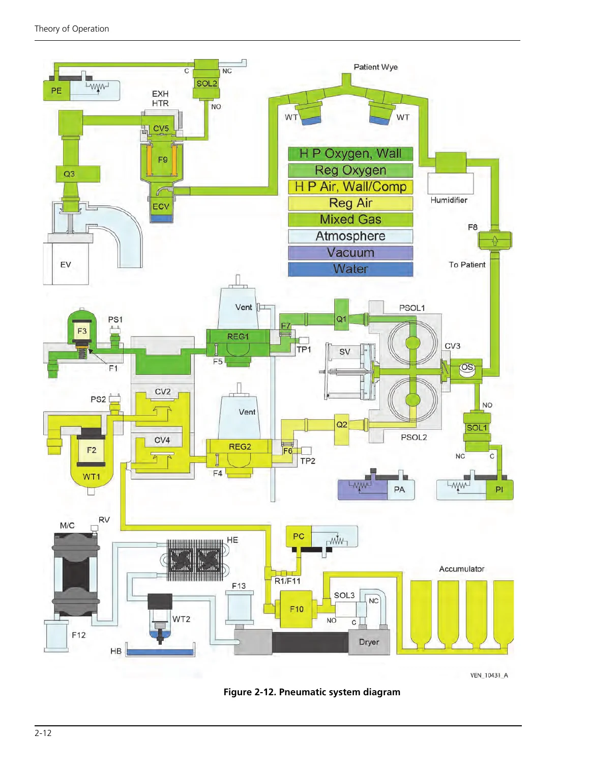
A large portion of the manual explains how the ventilator works internally. The pneumatic theory follows air and oxygen from the inlet fittings through filters, pressure switches, regulators, flow sensors, proportional solenoid valves, the safety valve, patient system, and exhalation module. Diagrams show gas-flow paths and component relationships, while accompanying text explains pressure regulation, mixing, triggering, inspiration and exhalation, oxygen monitoring, pressure monitoring, autozero functions, PEEP control, occlusion handling, and safety-valve operation.
The electrical section covers AC distribution, power conversion, backup power, the card cage, motherboard, breath delivery CPU and analog interface PCBAs, data key, GUI electronics, LCD and touch-frame hardware, alarm circuitry, inspiratory and exhalation electronics, and the optional 806 compressor electronics. Interconnect and component diagrams help relate electrical hardware to the pneumatic system. The manual also explains the dual-processor arrangement in which the BDU processor controls breath delivery while the GUI processor handles operator interaction and monitors BDU activity.
Testing, Service Mode and Troubleshooting
The Puritan Bennett 840 Ventilator System service manual gives structured procedures for POST (Power On Self Test), SST (Short Self Test), and EST (Extended Self Test), including when the tests are run, hardware requirements, test sequences, outcomes, and the use of Service Mode. Service Mode coverage includes test-result screens, diagnostic and event logs, alarm history, software and serial-number information, elapsed operating time, EST/SST summaries, date and time functions, automatic service functions, and oxygen-sensor calibration.
Performance verification is treated as a separate service discipline. The manual identifies required tools, test equipment, and service materials; preliminary cleaning and inspection; setup; calibrations; electrical safety and ground-isolation testing; regulator-pressure verification; serial loopback testing for the 10.4-inch GUI; use of the PTS 2000 Performance Test System and BreathLab 840 VTS software; and an alternate manual ventilator check. This gives technicians a defined path for verifying operation after maintenance or repair rather than relying only on component replacement.
Diagnostic coverage is equally detailed. The diagnostic-code chapter explains code structure and interpretation, POST fault handling, CPU LED arrays, system diagnostic logs, BDU POST analog-device testing, POST diagnostic codes, SST and EST sequences and codes, VGA LCD controller faults on the 9.4-inch GUI, and GUI screen-message troubleshooting. The alarm chapter then identifies alarm classifications and response information, making the manual useful when fault symptoms originate from either internal diagnostics or user-visible alarms.
Repair and Component Replacement Coverage
Chapter 8 provides the hands-on service and repair material. General sections cover repair safety, cleaning, electrical cables, pneumatic tubing, adhesives, leak testing, electrostatic-discharge control, replacement-part ordering, and post-service testing and calibration. The procedures then move into major assemblies and subassemblies, with removal, replacement, installation, and reassembly steps supported by photographs and drawings.
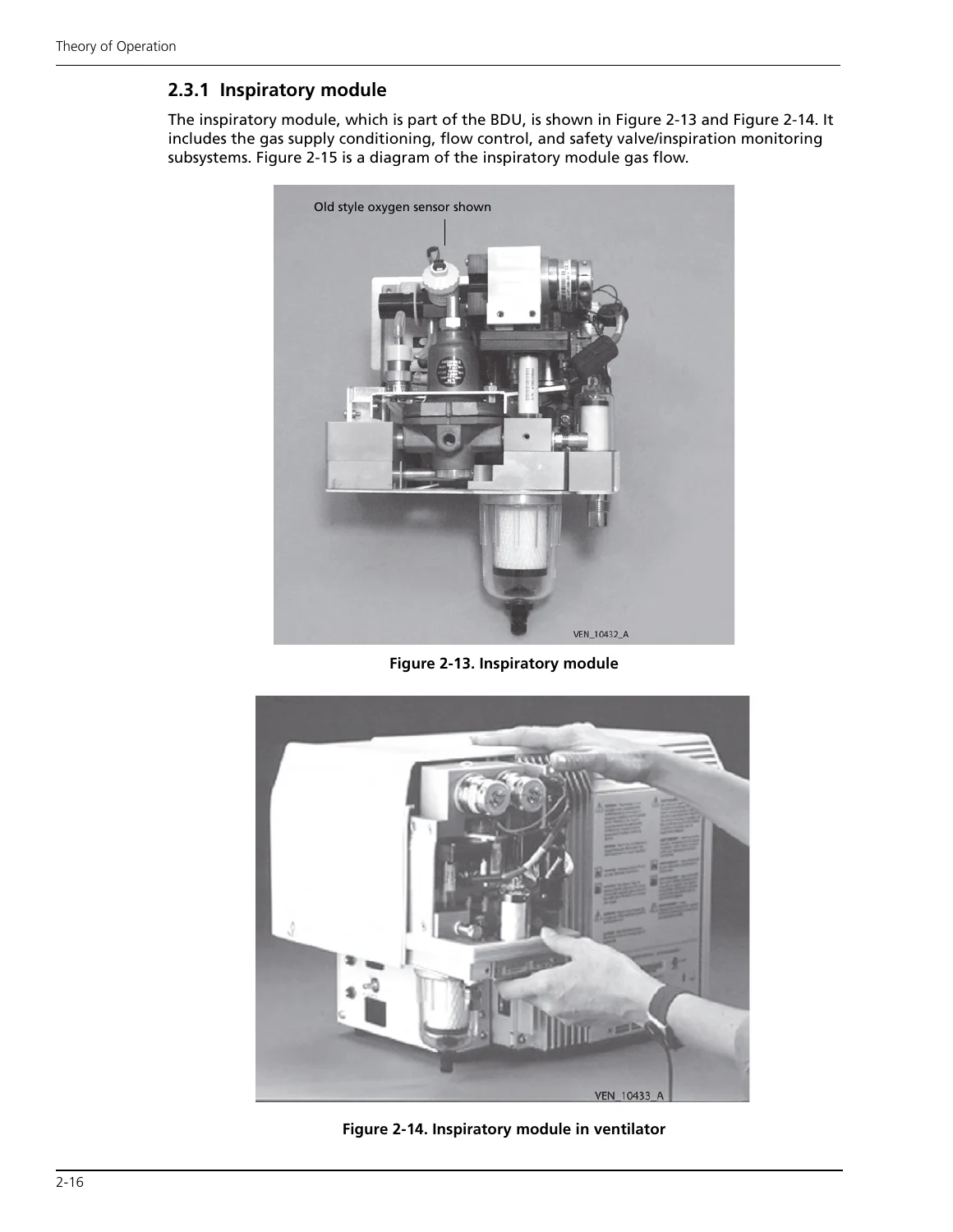
GUI repair coverage includes both 10.4-inch and 9.4-inch versions, with procedures involving GUI removal and installation, cables, housings, EMI shields, CPU PCBAs, compact flash components on applicable TE GUI CPU PCBAs, real-time clocks, LCD panels, touch-frame hardware, LED PCBAs, alarm assemblies, keyboards, and rotors. BDU service includes its installation and removal from supported carts, power cord and retainer, analog interface and breath-delivery CPU PCBAs, power supply, power switch, humidifier receptacle on applicable models, inspiratory module, exhalation module, housing, power indicator, and release handle.
The optional 806 compressor receives extensive coverage of its inlet filter, covers, fans, rear panel, accumulator fittings and O-rings, pneumatic hoses, plenum, heat exchanger, AC and data cables, compressor PCBA, air dryer and solenoid assembly, compressor assembly, and reinstallation work. Backup-power coverage addresses 802 and 803 BPS removal and installation, battery packs, and BPS PCBAs. Cart procedures include batteries, BPS components, casters, GUI mounting hardware, flex-arm inserts, and EMC-enhanced BDU chassis work.
Chapters Covered
- 1 General Information
- Product description, configuration information and accessories
- Specifications, compliance, technical information and ventilator setting ranges
- Tools, service materials, periodic maintenance and service kits
- Controls, indicators, serial numbers, software version and service philosophy
IMAGES PREVIEW

- 2 Theory of Operation
- Major subassemblies and operational overview
- Pneumatic system: inspiratory module, patient system, exhalation module and 806 Compressor Unit
- Electrical system: AC distribution, power supply, BPS, card cage, data key, GUI and control PCBAs
- Breath delivery, hardware monitoring and emergency modes
- 3 Self Tests
- Service Mode entry and background checks
- POST, SST and EST procedures and test behavior
- 4 Service Mode
- Service Mode access, diagnostic logs, alarm log and configuration displays
- EST/SST results, operating time, automatic functions and oxygen sensor calibration
- 5 Performance Verification
- Tools, setup, preliminary calibrations and verification guidelines
- Electrical safety, ground isolation, EST, regulator pressure and serial loopback tests
- PTS 2000/BreathLab 840 VTS and alternate manual ventilator checks
- 6 Diagnostic Codes
- Fault handling, diagnostic code interpretation and troubleshooting
- POST, SST and EST codes, diagnostic logs and GUI/LCD fault diagnosis
- 7 Alarm Handling
- Alarm classifications and responding to alarms
- 8 Service and Repair
- Repair safety, cleaning, tubing, leak testing, ESD control and post-service procedures
- 10.4-inch and 9.4-inch GUI repair
- Breath delivery unit, inspiratory module and exhalation module service
- 806 compressor, 802/803 BPS and cart service
- 9 Parts List
- Patient system and NeoMode accessories
- Flex arm, oxygen/air hose assemblies and power cords
- GUI, BDU, 806 compressor, BPS and cart major assemblies
Taken together, these chapters give a biomedical technician a system-level path from understanding the ventilator’s architecture to checking performance, interpreting diagnostic evidence, repairing supported assemblies, completing required post-service tests, and identifying parts. The combination of theory diagrams, service screens, test procedures, fault tables, repair photographs, and parts information makes the manual particularly useful when a problem crosses pneumatic, electrical, software-diagnostic, and mechanical boundaries.
Service the Puritan Bennett 840 with the Correct Reference at Hand
The Covidien Puritan Bennett 840 Ventilator System Service Manual 10067703 Rev D supports qualified service personnel working on inspection, preventive maintenance, calibration, performance verification, diagnostic-code investigation, alarm-related troubleshooting, GUI and BDU repair, pneumatic module service, backup-power work, compressor service, and parts identification. Following the documented procedures, test sequences, limits, and component information helps technicians approach service work with the values and checks specified for this ventilator system.
After payment, the manual is delivered as an instant PDF download with no physical shipping. It can be opened on compatible computers, tablets, and phones, and pages can be printed for convenient workshop or biomedical service use.
Reviews
There are no reviews yet.