
Crown Access 123 Electrical Service Manual M4.3-2045-001 – Forklift Repair & Diagnostic PDF
Original price was: $52.95.$34.95Current price is: $34.95.
Crown Access 123 Electrical Service Manual (M4.3-2045-001) – 192-page PDF covering Access 1/2/3 modules, event codes, calibration, wiring diagrams, hydraulics and full forklift repair procedures.
Description
Crown Access 123 Electrical Service Manual – M4.3-2045-001
The Crown Access 123 Electrical Service Manual is the technician-level reference for diagnosing, calibrating, and repairing Crown electric forklifts running the Access 1, 2, and 3 control architecture. Published under document number M4.3-2045-001, this 192-page PDF works through the complete Access 123 system – the Access 1 Display Control Module (DCM), the Access 2 Hydraulic Control Module (HCM), and the Access 3 Traction Control Module (TCM) – covering the menu trees, event code logic, wiring diagrams, hydraulic schematic, and hardware repair procedures a working technician needs at the truck. Whether you are chasing a fault code, calibrating an accelerator potentiometer, or pulling a traction motor out of the drive unit, this Crown forklift electrical service manual keeps you inside the correct procedure.
File Details
- Manual type: Electrical Service Manual
- Brand: Crown
- System: Access 123 (Access 1 DCM / Access 2 HCM / Access 3 TCM)
- Document number: M4.3-2045-001
- Language: English
- Page count: 192
- File format: PDF
Chapters Covered
- Operator Display and Navigation
- User Level and Message Mode
- Hour, Event and Utilities Menus
- Service Menus (Level 2 and Level 3)
- Calibration (C1 Accelerator, C2 Battery)
- Features (F1 – F13)
- Performance Setup (P1, P2, P3)
- Analyzer (A1 – A4)
- Battery Care, Charging and Removal
- Contactors (Steering, Line, Pump)
- Distribution Board
- Drive Unit and Traction Motor
- Mast, Carriage and Column Rollers
- Parking Brake and Service Brake
- Potentiometers
- Steering and Steer Axle
- Switches
- Tilt Cylinder
- Event Codes
- Wiring Diagrams and Power Cables
- Hydraulic Schematic
- Glossary
Operator Display, Menu System and Calibration
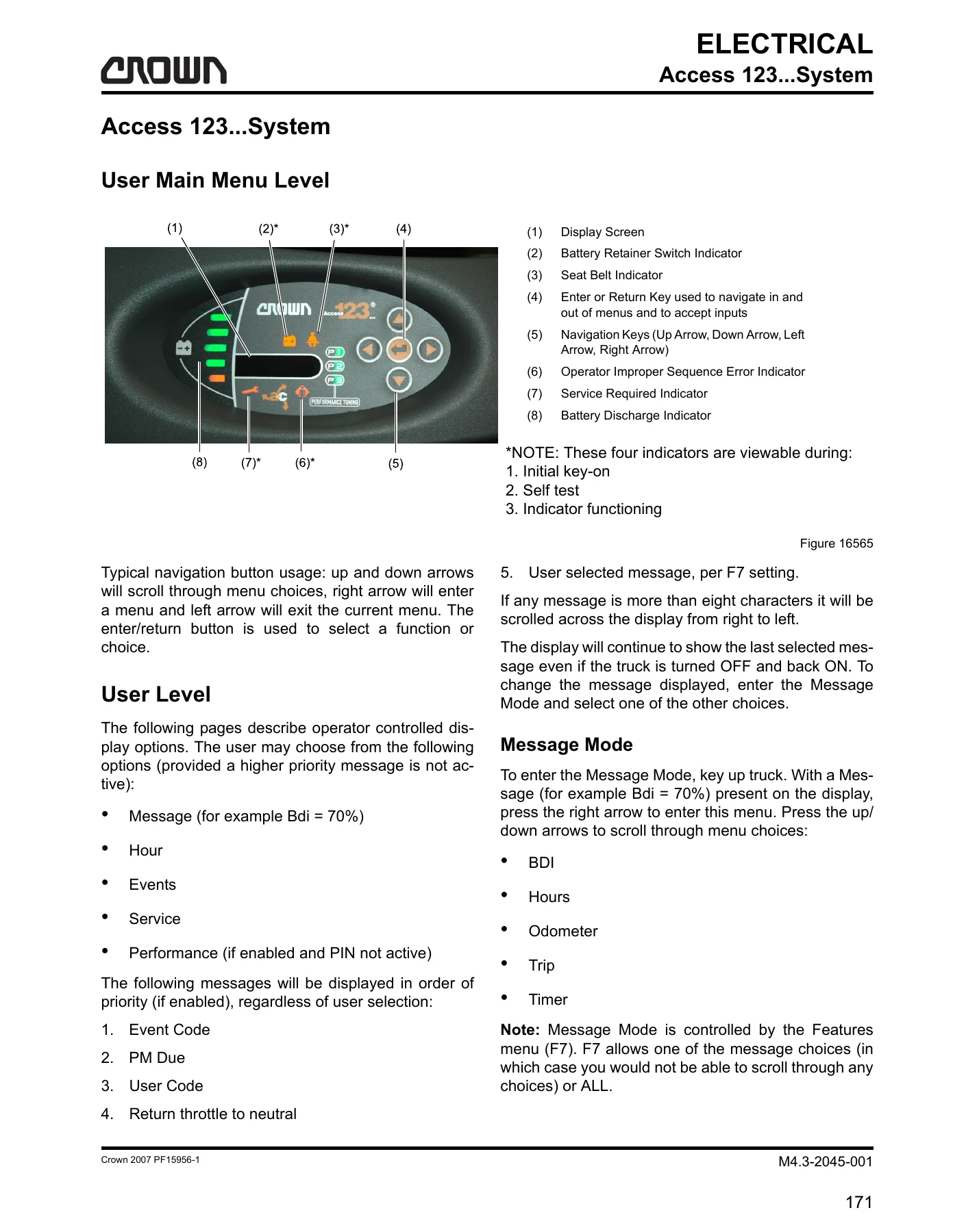
The first third of the manual explains what the operator and technician actually see on the Access 1 display: the battery discharge indicator, battery retainer switch indicator, seat belt indicator, service-required light, operator sequence error indicator, and the four-way navigation keypad. From there it documents the User Level message mode (Bdi, Hours, Odometer, Trip, Timer) and the full Hour / Event / Utilities menus that live behind the Service menu password. Calibration (C1 Accelerator Pedal and C2 Battery Adjustment) is laid out step by step – including the exact volt values you should see at each prompt, the direction-switch sequencing, and the Save? Y / Save? N confirmation path. The Features menu (F1 through F13) is documented feature by feature: language, metric, TMM, hour meter selection, battery type (36V or 48V), lift system (DC or AC), message mode, user performance, user codes, auto park brake, and accessory flow rates in GPM.
Performance, Analyzer and Service Menus
The Performance chapter covers P1, P2, and P3 setup – forward and reverse speeds for 36V and 48V trucks, acceleration rates, Bdi lockout, plugging, coast, and the Perf > FL (fork lift height) settings – with factory defaults shown for every value. The Analyzer menu (A1 Status, A2 Inputs, A3 Outputs, A4 Test Outputs) is fully documented, including the meaning of every monitored input on Access 1, Access 2, and Access 3: RAS, TLT, TBS, TLMS, AXS1, BRES, HGTS1, TMM voltage ranges, HSS, M2 speed and temperature, M2 current, forward/reverse switches, brake switch, seat switch, ACS, POT1, travel speed, M1 speed, M1 temperature, M1 current, Bdi, and battery voltage. Output test procedures for the lamptest, alarm, lift contactor, steer contactor, tilt limit solenoid, line contactor, and both controller cooling fans are shown with the expected voltage windows per truck voltage.
Hardware Service: Battery, Contactors, Distribution Board
Battery coverage includes safety rules, electrolyte level and specific gravity targets (1.265 to 1.285 fully charged), charging and equalizing schedules, cleaning, troubleshooting, and full removal and installation procedures with lifting-device notes. The contactor chapter documents inspection and contact replacement for the steering contactor (S), line (L), and pump (P) contactors, with coil resistance values (about 174 ohm for the steering contactor and about 44 ohm for the line and pump contactors) and torque values. The distribution board chapter identifies every connector (CA201 through CA207), every test point (TP1 through TP4), relay functions (K1, K2A, K2B), fuse ratings (FU4, FU5, FU8), and the J2 and J3 jumper configurations that control when the travel alarm ALM3 sounds.
Drive Unit, Traction Motor, Mast and Brakes
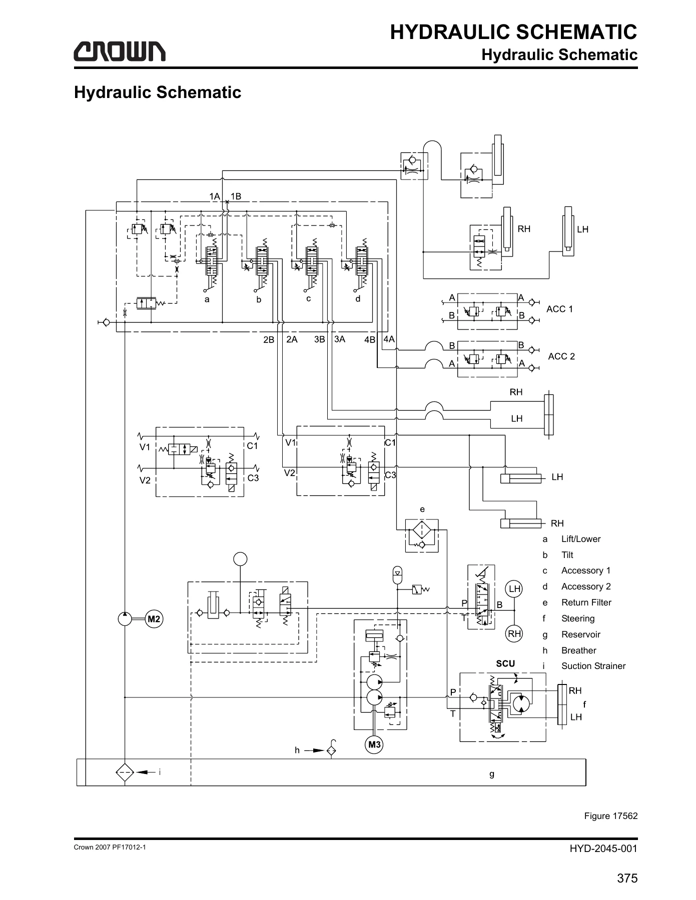
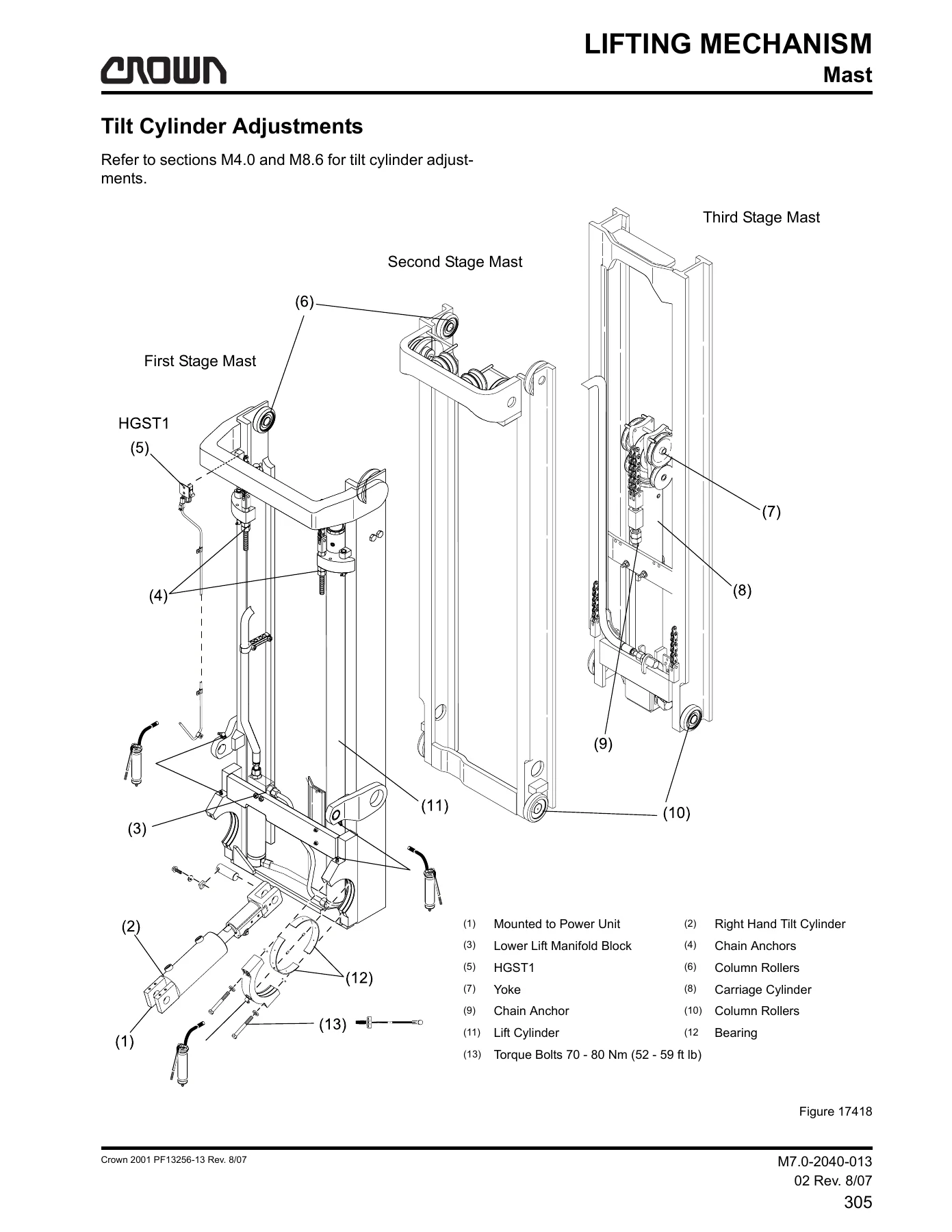
The drive unit chapter covers oil capacity (5.7 L / 6 qt of 80-90W gear lube), drain / fill / check plug locations, oil change intervals, and mounting bolt torque (545 Nm / 400 ft lb). Traction motor removal is documented with lift points, gasket eliminator procedures, the 1st reduction pinion heating step (205 C / 400 F maximum for 45 to 75 minutes), and the five mounting screw torque (47.5 +/- 6.8 Nm / 35 +/- 5 ft lb). Mast coverage includes column roller shimming, carriage side thrust roller adjustment, lift chain tension, tilt cylinder removal, and the TL / TT / Quad mast procedures. The parking brake and service brake chapters document shoe inspection (2.0 mm minimum lining), piston and seal replacement, bleeding, and the park brake release manifold with the hand pump and manual release valve. Wiring diagrams, the full hydraulic schematic, the connector glossary, and the wire harness chart round out the volume.
Event Codes and Diagnostics
The event code chapter is the practical heart of the manual for fault-finding. Every code from 110 (CAN communication) through 399 is listed with the display description, the step-by-step diagnostic path, the voltage windows to expect at each test point, and the decision tree that leads to either a wiring repair, a component replacement, or an Access module replacement. Codes 119, 123, 130, 131, 133, 134, 163, 199, 201 through 210, 214 through 225, 299, 301 through 309, 311 through 325, and the FWD/REV and No Traction symptoms are all documented with the same level of detail.
Why This Manual Matters
Crown Access 123 trucks are still in daily service, and the electronics on them are not forgiving of guesswork. If you swap an Access module without following the calibration steps, the truck may not move. If you replace a contactor and skip the coil resistance check, you may burn the driver on the new module. If you pull a traction motor without the correct pinion heating procedure, you can damage the shaft fit. This manual gives you the exact values, sequences, and torque figures the factory uses, plus the analyzer menu paths to verify every input and output before you start swapping parts.
IMAGES PREVIEW
Instant PDF Delivery
This Crown Access 123 electrical service manual is delivered as a downloadable PDF the moment your order completes – no shipping, no waiting, no oversized binder to lose on the shop floor. Open it on a laptop at the truck, print the pages you need for the job at hand, or pull it up on a tablet while you are standing at the mast. The file is organized so the menu chapters, event codes, and wiring diagrams are all in one place, and you can search across the whole 192 pages whether you are diagnosing a single fault code or rebuilding the drive unit from scratch. If you service Crown forklifts with the Access 123 system, this is the reference you keep on the machine.
Reviews
There are no reviews yet.