
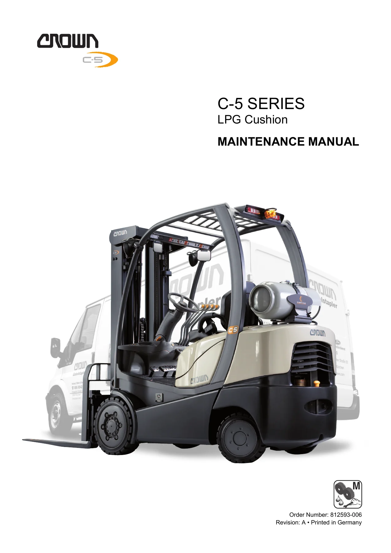
Crown C-5 Series LPG Cushion Forklift Maintenance Manual – 4000 to 6500 lb Capacity Models
Original price was: $34.95.$21.95Current price is: $21.95.
Complete Crown C-5 Series LPG cushion forklift maintenance manual covering 1814 kg to 2948 kg (4000-6500 lb) trucks, the John Deere 2.4 L LPG engine, hydraulics, power and drum brakes, Access 1 2 3 diagnostics, lifting mechanism, cylinders and full wiring and hydraulic schematics.
Description
This Crown C-5 Series LPG Cushion Forklift Maintenance Manual is the workshop reference for the C-5 cushion tire trucks running LPG fuel, spanning the 1814 kg, 2268 kg, 2722 kg and 2948 kg rated capacity models. It is written for the service technician rather than the operator: it contains troubleshooting information intended to let a qualified technician locate and solve problems as they occur, plus the procedures, torque values and specifications needed to carry out the work correctly.
File Details
- Manual type: Maintenance / service repair manual
- Brand: Crown
- Series: C-5 Series LPG Cushion
- Publisher: Crown Gabelstapler GmbH & Co. KG, European Headquarters, Moosacher Str. 52, 80809 Munich, Germany
- Language: English
- Page count: 482 pages
- File format: PDF
Chapters Covered
- Introduction – Operator Instructions, Operator Training, Service Training, Ordering Spare Parts, Ordering Documentation, Manual Structure
- Safety – General Maintenance Instructions, Control of Hazardous Energy, Work in Ventilated Areas, Handle Propane Gas Safely, Cooling System Safety, Battery Safety Rules, Battery Care, Charging, Jump Starting, Prevent Bypass Starting, Lockout-Tagout
- Safety (continued) – Manually Lowering the Mast, Manually Releasing and Applying the Parking Brake, Hydraulic Safety, Towing Truck, Lifting and Blocking, Drive Wheels, Steer Wheels, Side, Wheel Stands, Mast, Blocking Masts, Disconnecting Tilt Cylinders, Removing the Mast, Removing Counterweight, Cleaning of Material Handling Equipment
- Inspection & Lubrication – Operators Daily Checklist, Lubricants Aerosols & Service Supplies, Planned Maintenance Summary Chart, Component Access, Seat Deck, Floorplates, Lubrication, Engine Break-In, Daily Operator Checks
- Inspection & Lubrication (continued) – 500 Hour Inspection and Lubrication Charts, 1000 Hour Inspection and Lubrication Charts, 2000 Hour Inspection and Lubrication Charts, 3000 Hour Inspection and Lubrication Charts, Torque Values, Grade, Metric Torque Values
- Componentry – Audible Indicators, Battery, Fuses, Lights, Miscellaneous, Modules, Relays, Resistors, Sensors, Solenoid Valves, Switches
- Hydraulic – Hydraulic System, Hydraulic Lines and Fittings, Reservoir, Capacity, Filters, Drift Tests, Cylinder and Circuit Bleeding, Hydraulic System Troubleshooting, Hydraulic System Checks & Adjustments, Hydraulic Circuitry, Steering
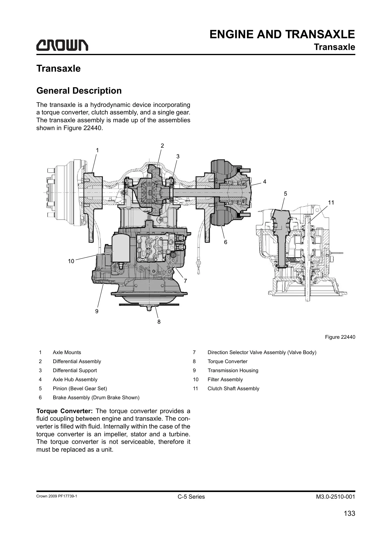
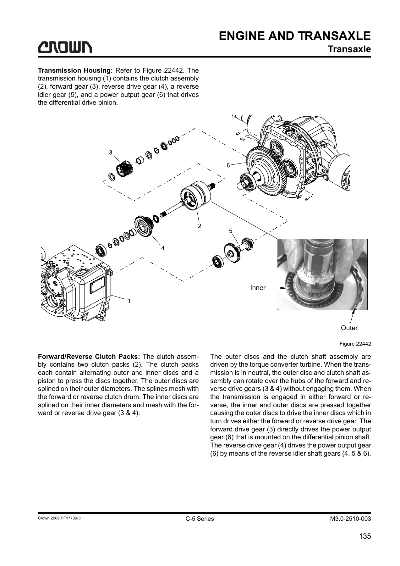
- Engine and Transaxle – Transaxle, General Description, Checking Transaxle Fluid Levels, Changing Transaxle Fluids, Drive Axle Fluid Change, Control Valve Body Replacement, Drive Tire Replacement, Engine Basics, Engine Specifications, Engine Identification, Engine Break-In, Engine Operation
- Engine and Transaxle (continued) – LPG Fuel System, LPG Fuel System Safety, Fuel Requirements, Handling and Storing LPG Fuel, Fuel Leak Check Procedure, LPG Bottle, Fuel Manifold Block, Fuel Filter and Fuel Pressure Switch, Shutoff Valve and Fuel Lockoff Solenoid, Electronic Pressure Regulator, Refueling LPG Truck, LPG Bottle Removal and Installation
- Engine and Transaxle (continued) – Air Intake Filter and Exhaust System, Carburetor, UTTP Sensor, Air Throttle Actuator, MAP Sensor, PCV Valve, Oxygen Sensor, Muffler, Air Cleaner Maintenance, Carburetor Maintenance, PCV Valve Maintenance, Air/Gas Mixer Assembly, Exhaust Manifold Removal and Installation
- Engine and Transaxle (continued) – Engine Lubrication System, Engine Oil, Engine Oil Change, Checking Engine Oil Pressure, Oil Pan Removal and Installation, Oil Pressure Regulation Valve, Oil Pick-Up Tube, Oil Pump Removal and Installation, Oil Pressure Sensor
- Engine and Transaxle (continued) – Electronic Control System, Ignition System Operation, Engine Control Unit (ECU) Operation, Engine Starting Mode, Engine Running Mode, Monitoring Engine Parameters, CAM Sensor, ECU Removal and Installation, Battery, Alternator, Starter, Power Relay Module, Ignition Coils, Spark Plugs, Engine Wiring Harness
- Engine and Transaxle (continued) – Cylinder Head and Valves, Rocker Arm Cover Removal, Rocker Arm Assembly Disassembly, Cylinder Head Removal and Installation, Install Rocker Arms, Install Rocker Arm Cover
- Engine and Transaxle (continued) – Crankshaft and Flywheel, Crankshaft Pulley Removal and Installation, Flywheel and Flywheel Housing, Rear Oil Seal, Timing Gear Cover
- Electrical – Electrical System, Wiring Colour Codes, Switches, Specialty Switches, Other Electrical Symbols
- Electrical (continued) – Access 1 2 3, ACCESS 1 Display, Operator Mode, Event Codes, Truck Hours, Ground Speed, Fuel Rate, Service Mode, Analyzer, Status, Inputs, Outputs, TestOuts, Calibration, Features, Hours, Events, Performance, Utility
- Electrical (continued) – Control Modules, Display Module (ACCESS 1), Engine Control Unit (ACCESS 3), Analog-to-Digital and Digital-to-Analog Converters, Microprocessor (CPU), Memory, Internal Power Supplies, Functions of the ECU, Sensor Monitoring, Diagnostic Trouble Codes (DTC)
- Electrical (continued) – Event Code Introduction, Event Codes 29.03 through 1071.06, Direction Lever Sensor, Park Brake Issue, Tilt Lever Issue, Operation Messages, Shutdown/Derate Messages, Engine Protection, Derate Event Codes
- Brake – Power Brake System, Power Brake Pedal Bridge Assembly, Accelerator Pedal, Accelerator Pedal Position Sensor (ACCELPED), Brake Pedal, Inch Pedal, Brake Switch, Brake Valve, Brake Valve Linkage Lubrication, 3 and 2 Pedal Bridge Assembly, Power Brake Operation, 3000 Hour Inspection, Power Brake Removal and Disassembly, Power Brake Lining and Stator Inspection and Replacement, Service Brake Piston Wiper and Seal Inspection/Replacement, Power Brake Assembly, Power Brake Installation, Power Brake Bleeding
- Brake (continued) – Service Brakes, Parking Brakes, Parking Brake Operation, Parking Brake Disassembly, Parking Brake Piston Wiper & Seal Inspection/Replacement, SAHR Cap Pre-Assembly, Power Brake Manifold, Manually Releasing and Applying Parking Brake, Parking Brake Solenoid, Pressure Unloading Valve, Park Brake Pressure Switch
- Brake (continued) – Drum Brake System, Drum Brake Pedal Bridge Assembly, Accelerator Pedal, ACCELPED, Brake Pedal, Inch Pedal, Master Brake Cylinder, Drum Brake Operation, Brake Drum Removal, Drum Brake Wear Check, Brake Drum to Shoe Clearance, Brake Shoe Removal and Installation, Wheel Cylinder Removal/Installation, Bleeding Drum Brakes
- Steering – Steer Control Unit, Steering Column, Steering Wheel Removal, Steering Wheel, Steering Column, Gas Cylinder, Steer Column Final Assembly, Steer Axle Assembly, Steer Axle, Steer Tire Replacement, Steer Tire Hub
- Lifting Mechanism – Lift Chains, Inspection, Wear, Rust and Corrosion, Cracked Plates, Tight Joints, Protruding or Turned Pins, Chain Side Wear, Lift Chain Lubrication, Lift Chain Replacement, Chain Anchors and Pulleys, Leaf Chain Disconnect, Fork Inspection, Abrasion, Blade Measurement, Overloading, Fatigue, Bent or Twisted Forks, Hanger
- Cylinders – Mast Cylinder, Cylinder Disassembly, Seals, Seal Removal, Seal Installation, Rod U-Cup Installation, Cylinder U-Cup Installation, Cylinder Assembly, Cylinder Bleeding and Flushing, Lift Circuit Bleeding and Flushing, Lift Drift Test, Steer Cylinder, Sideshifter Cylinder
- Attachments – Sideshifter Removal, Sideshifter Installation, Sideshifter Maintenance
- Glossary – Component connection, location, function and diagram reference charts
- Wiring Diagrams – Introduction to Diagram Usage, Schematic, Pictorials, Electrical Diagrams Index, Truck and Engine Schematics, Ignition/Charging, Power Distribution, Transmission and Pedal Bridge, Engine ECU and CAN, Keyswitch/Travel Alarm/Horn/Park Brake/Fuel Sensor, Front Cowl/Power Distribution, Interlock Circuit, Light Accessories, InfoLink, ODC, Wire Harnesses
- Hydraulic Schematic – Hydraulic Schematic, On-Demand Cooling
Taken as a whole, this C-5 Series LPG cushion forklift maintenance manual gives a technician a single continuous reference for the whole truck. It opens with the safety groundwork that has to be in place before any work begins, moves into the planned maintenance intervals and lubrication points, then works through the truck system by system: the hydraulics and their relief valve settings, the LPG fuel system and its electronic pressure regulator, the John Deere 2.4 litre engine and the transaxle behind it, the Access 1 2 3 electrical architecture with its full event code diagnostics, both the power and drum brake systems, the steering, the lift chains and forks, and the cylinders themselves. Torque charts and metric fastener values are gathered in one place, and the back of the book carries the wiring diagrams, hydraulic schematic and glossary that make circuit tracing practical.
Models and Capacities Covered
The manual applies to C-5 Series cushion trucks with LPG fuel engines. The model number example used throughout is C-5 1000-60, which decodes as a C-5 series cushion truck (truck type 0 = cushion, 5 = pneumatic) with an LPG fuel engine (engine type 0) and a rated capacity of 2722 kg. The four capacity ratings listed in the manual are 1814 kg (4000 lb), 2268 kg (5000 lb), 2722 kg (6000 lb) and 2948 kg (6500 lb). Actual rated capacity may vary depending on special equipment or modifications, so the capacity plate on the overhead guard governs. The truck data plate is located on the left hand side, lower portion of the overhead guard under the seat deck, and carries both a model number and a truck data number.
Engine and Powertrain Coverage
The engine is a John Deere 2.4 litre, four cylinder, LPG fuelled internal combustion unit: 86 mm bore, 105 mm stroke, 10.5:1 compression ratio, firing order 1-3-4-2, 45 kW / 60 HP output, 800 RPM slow idle, 2960 RPM fast idle and 2800 RPM rated speed at full load. Each engine carries a 13-digit engine serial number on a plate on the left hand side of the cylinder block behind the starter motor.
Engine coverage runs from break-in oil and daily fluid checks through the lubrication system, oil pump and oil pressure regulation valve, cylinder head and valve train, crankshaft and flywheel, rear oil seal, and timing gear cover. The electronic control system chapter explains the ECU, camshaft position sensor signal, ignition coils and spark plugs. On the fuel side, the manual covers the LPG bottle and bracket, fuel manifold block and relief valve, fuel filter and pressure switch, shutoff valve and fuel lockoff solenoid, electronic pressure regulator, carburetor and air/gas mixer assembly, UTTP and MAP sensors, oxygen sensor, PCV valve and the combined catalytic converter and muffler.
Hydraulic and Brake Coverage
The hydraulic chapters give reservoir capacities (41.6 litres for the C-5 cushion and 53.0 litres for the C-5 pneumatic), filter and strainer service intervals, lift and tilt drift test limits, and bleeding procedures for the lift, tilt, sideshift, steer and brake circuits. Control valve primary and secondary relief valve pressure settings are broken out by truck capacity, and there is a full adjustment procedure for the load sensing priority flow divider relief valve inside the pump, including the different adjusting screw locations and wrench requirements for the smaller and larger pumps.
Both brake systems are covered in depth. The power brake section spans the pedal bridge assemblies, accelerator pedal position sensor, brake valve and linkage adjustment, 3000 hour lining inspection, brake removal and disassembly, piston, wiper and seal service, SAHR cap pre-assembly, parking brake operation and manual release, the power brake manifold, pressure unloading valve and park brake pressure switch. The drum brake section covers the master cylinder, drum removal, wear limits, drum to shoe clearance setting by both the installed and removed methods, shoe removal and installation, wheel cylinder service and bleeding.
Electrical Diagnostics and Access 1 2 3
A large part of the manual is devoted to the Access 1 2 3 system. It explains Operator Mode, Service Mode and the password-protected menus, then walks through the Analyzer (Status, Inputs, Outputs, TestOuts), Calibration, Features, Hours, Events, Performance and Utility menus with the expected voltage or value ranges for each input. The event code section covers the SAE J1939 two-part code structure, an FMI explanation chart, and individual troubleshooting trees for the codes this truck logs, from accelerator pedal and air throttle faults through oil pressure, coolant temperature, transaxle temperature, CAN communication loss, ignition coil circuits and the fan control codes. Engine protection derate thresholds and the resulting power reductions are tabulated.
Lifting Mechanism, Cylinders and Attachments
Lift chain coverage includes wear measurement using a chain wear scale, the 3% elongation replacement point for 16 mm, 19 mm and 25 mm pitch chain, corrosion and cracked plate inspection, tight joint and turned pin identification, lubrication practice and the leaf chain disconnect procedure. Fork inspection covers abrasion limits, blade measurement with fork wear calipers, the 10% wear thickness chart, fatigue crack detection, and how to check a fork for bend or twist using a carpenter’s square.
Cylinder chapters provide disassembly, seal removal and installation, U-cup installation technique for both small and large cups, assembly, bleeding and flushing, and the lift drift test. The steer cylinder and sideshifter cylinder each get their own removal, disassembly, assembly and installation procedures with torque values.
Safety and Planned Maintenance
The safety chapter is not boilerplate: it sets out the control of hazardous energy requirements, the lockout-tagout sequence, tag placement on the steering wheel and LPG cylinder valve, propane handling rules, cooling system precautions, battery charging and jump starting, and the approved procedures for manually lowering the mast and manually releasing or applying the parking brake. Towing requirements, pull and push force calculations, lifting and blocking methods for drive wheels, steer wheels, sides and wheel stands, mast blocking, tilt cylinder disconnection, mast removal and counterweight removal are all documented.
Planned maintenance is organised around 500, 1000, 2000 and 3000 hour intervals with separate inspection and lubrication charts for each, an operators daily checklist, a full lubricant and fluid identification chart with part numbers and package quantities, alternate lubricant equivalents, and metric torque charts for hex head cap screws and nuts, countersunk head screws, socket head cap screws and flanged hex head fasteners across classes 8.8, 10.9 and 12.9.
What This Manual Lets You Do
With this Crown C-5 Series LPG cushion forklift maintenance manual on hand you can carry out scheduled servicing against the correct intervals and lubricants, diagnose and clear the event codes the truck reports, set the hydraulic relief pressures to the values the truck actually needs, service the power or drum brakes including the parking brake assemblies, adjust the brake and inch pedal linkage, trace a wiring fault through the schematics, check and replace lift chains and forks against published wear limits, and rebuild the mast, steer and sideshifter cylinders.
Getting the torque figures and pressure settings right matters on a machine that lifts up to 2948 kg. A relief valve set at the wrong pressure, a brake lining run past its wear limit, or a lift chain kept in service past 3% elongation all have consequences beyond the component itself. The manual gives the numbers the truck was built to, rather than a general estimate.
IMAGES PREVIEW
The file is delivered as an instant PDF download, so there is nothing to ship and nothing to wait for. It opens on a laptop, tablet or phone in the workshop, and pages can be printed when a paper copy is easier to work from next to the truck.
Reviews
There are no reviews yet.