
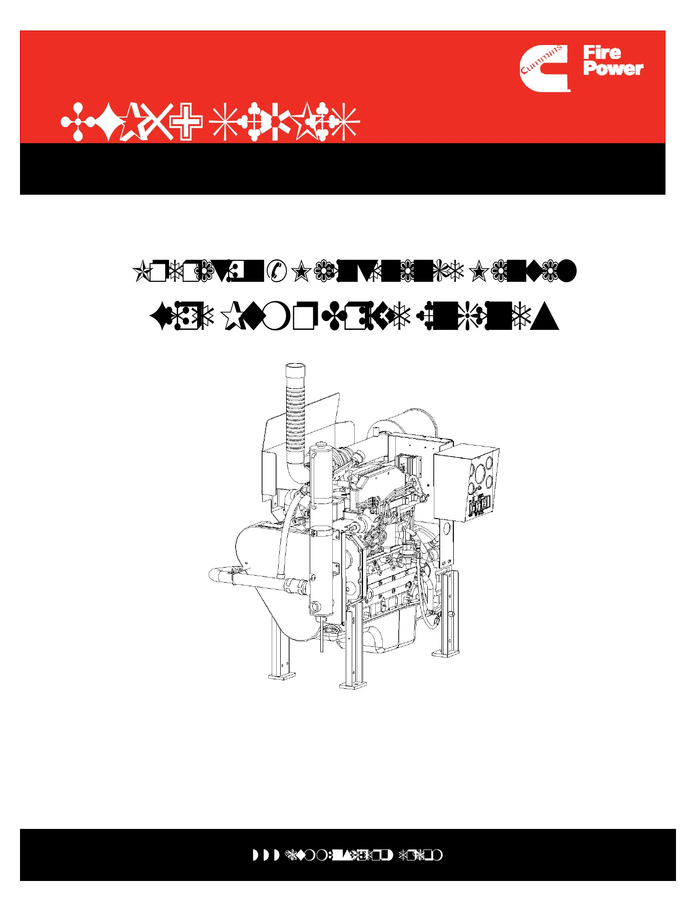
Cummins CFP59 Series Fire Pump Drive Engine Operation & Maintenance Manual – CFP59-F10 F15 F20 F25 F40 F45 F50 F55 PDF
Original price was: $51.95.$34.95Current price is: $34.95.
Complete Cummins CFP59 Series Fire Pump Drive Engines Operation & Maintenance Manual in PDF. Covers CFP59-F10, F15, F20, F25, F40, F45, F50 and F55 models with installation, operation, maintenance, specifications, troubleshooting and assembly drawings.
Description
Cummins CFP59 Series Fire Pump Engine Operation & Maintenance Manual
This PDF is the complete Operation & Maintenance Manual for Cummins CFP59 Series fire pump drive engines. It is Drawing No. 9776, Section 0, Rev. 02-07, and it covers the CFP59-F10, CFP59-F15, CFP59-F20, CFP59-F25, CFP59-F40, CFP59-F45, CFP59-F50 and CFP59-F55 models. The manual is written for the people who install, operate, maintain and troubleshoot these fire pump engines, with procedures, system diagrams, maintenance schedules, specifications and assembly drawings in one 552-page document.
File Details
- Manual type: Operation & Maintenance Manual
- Brand: Cummins
- Model series: CFP59 Series Fire Pump Drive Engines
- Covered models: CFP59-F10, CFP59-F15, CFP59-F20, CFP59-F25, CFP59-F40, CFP59-F45, CFP59-F50, CFP59-F55
- Language: English
- Page count: 552
- File format: PDF
- Document number: Drawing No. 9776
- Revision: Rev. 02-07
- Date shown: 2005
Chapters Covered
- Section 1 – Introduction
- Section 2 – Engine Identification
- Section 3 – Installation and Operation
- Section 4 – Maintenance Guidelines
- Section 5 – Maintenance Procedures
- Section 6 – System Diagrams
- Section 7 – Adjustment, Repair and Replacement
- Section 8 – Service Literature
- Section 9 – Service Assistance
- Section 10 – Maintenance Specifications
- Section 11 – Warranty Information
- Section 12 – Troubleshooting
- Section 13 – Assembly Drawings
Introduction and Engine Identification
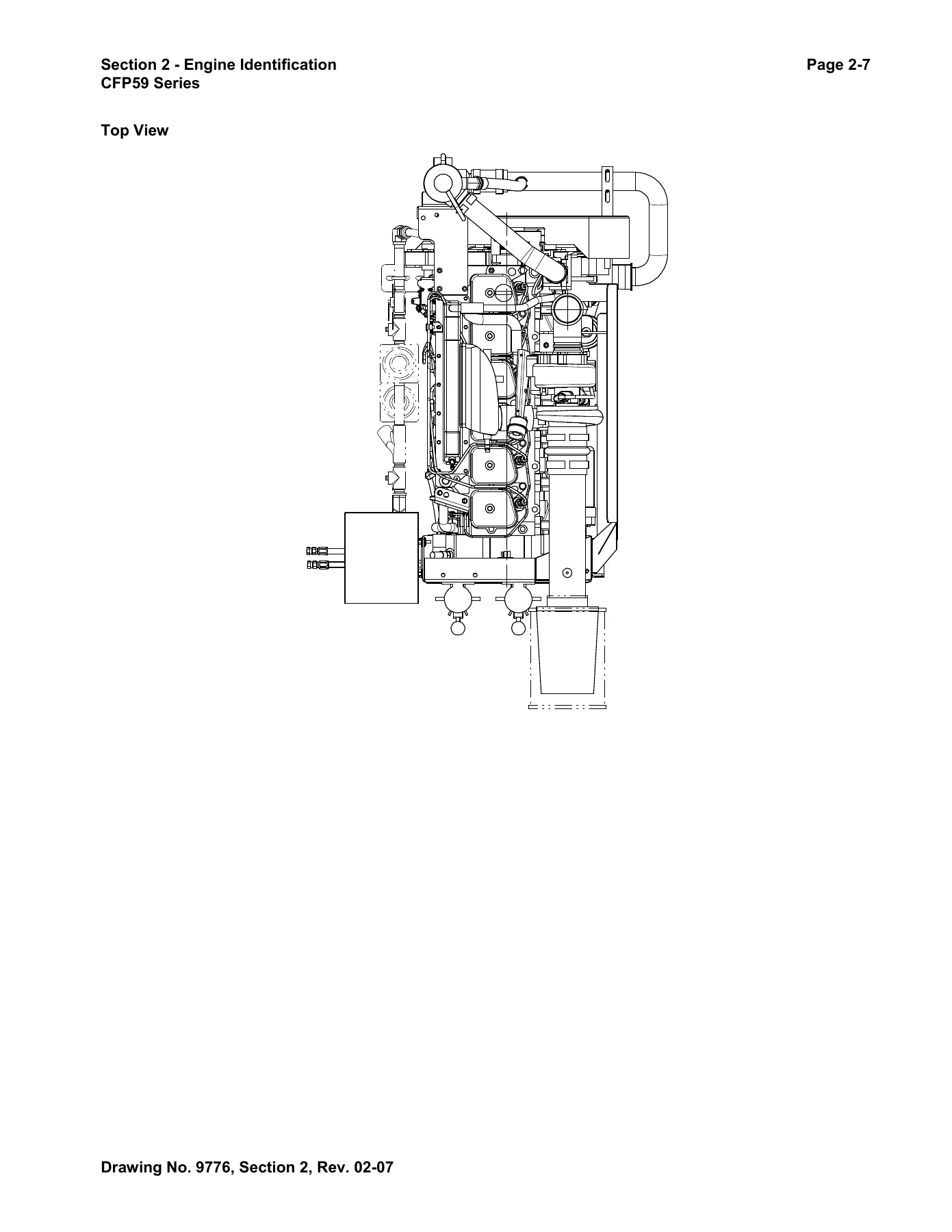
The opening sections set up the manual for safe use and correct engine identification. Section 1 covers general safety instructions, symbols, illustrations, general cleaning instructions and acronyms. Section 2 identifies the fire pump engine family, overspeed switches, operating speed, control system, external engine components and views, instrument panel, fire pump identification, Factory Setting Tag and fuel injection pump dataplate. These pages matter when you need to confirm the engine model, read the correct setting tag or match a component view to the engine in front of you.
Installation and Operation
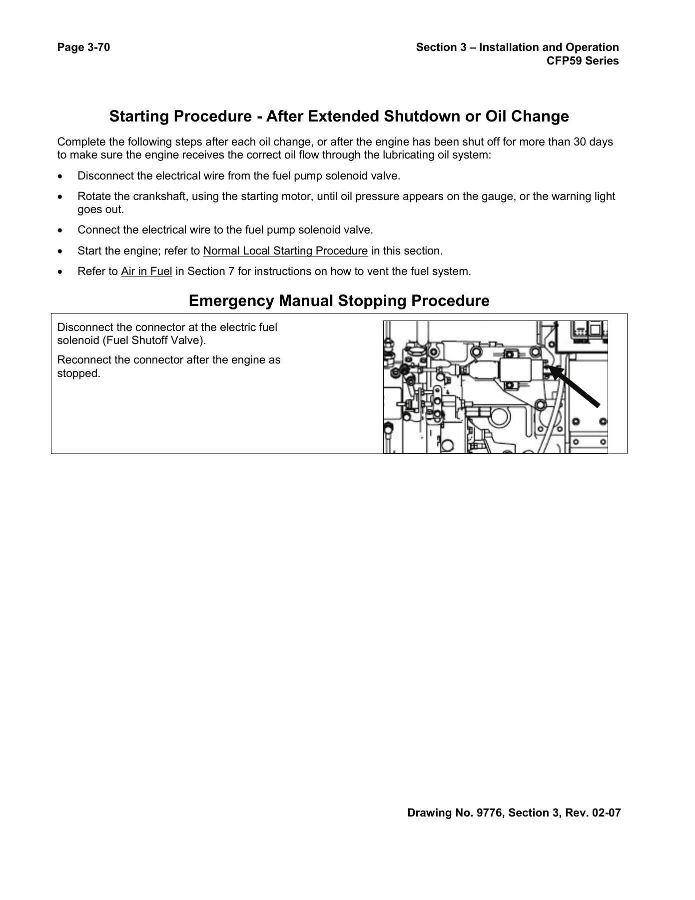
Section 3 is the practical installation and operating guide. It covers physical engine installation, fuel supply installation, fire pump installation, raw water supply installation, battery and electrical installation, signal and control installation, coolant system preparation, lubricating oil system preparation and fuel system preparation for the different CFP59 model groups. It then walks through pre-start inspections, pre-lubrication, lubrication of zerk fittings, engine-to-pump alignment, initial start-up, initial start, second start, rated speed setpoint adjustment for each model group, overspeed setpoint adjustment and testing, crank terminate adjustment and testing, isolated acceptance testing, integrated acceptance testing, general operating information, normal remote and local starting, battery jumpering, engine operation, emergency manual starting procedures, starting after extended shutdown or oil change, and emergency manual stopping.
Maintenance Guidelines and Procedures
Section 4 gives the maintenance framework: tool requirements, the maintenance schedule and a maintenance record form. Section 5 turns that schedule into procedures across daily, weekly, three-month or 250-hour, six-month or 500-hour, yearly or 1000-hour, two-year or 2000-hour and four-year or 5000-hour intervals. The procedures include air intake filter and piping checks, coolant level checks, crankcase breather checks, lubricating oil level checks, fuel-water separator draining, aftercooler and charge air cooler piping inspection, coolant heat exchanger and heater piping checks, fuel tank bleeding, raw water strainer cleaning, battery condition checks, test running, hose condition checks, coolant heater checks, heat exchanger zinc plug inspection, electrical component inspection, turbocharger mounting nut checks, engine mounting bolt checks, cooling system condition checks, air cleaner service indicator checks, fuel pump checks, lubricating oil and filter changes, fuel filter changes, charge air cooler cleaning, output shaft lubrication, cooling system drain and flush, coolant filter changes, fuel supply line venting, injection pump venting, overspeed switch checks, drive belt and tensioner checks, valve lash adjustment, turbocharger inspection, vibration damper inspection, water pump inspection, engine steam cleaning and overhead set inspection.
System Diagrams, Repair and Replacement
Section 6 provides flow diagrams for the fuel system, lubricating oil system, cooling system, air intake system and exhaust system, plus an assembly diagram for raw water piping. Section 7 is the adjustment, repair and replacement chapter. It covers belt guard and belt service, automatic belt tensioner service, coolant heat exchanger, coolant heater, coolant hoses, raw water pressure regulator, raw water solenoid valve, water temperature gauge, coolant temperature sender and switch, coolant thermostat, coolant water pump, alternator checks and testing, alternator and bracket service, battery isolator, engine harness, voltmeter, battery testing and service, battery cables, starter motor, crank solenoid assembly, control panel fuse replacement, exhaust manifold and shield service, exhaust restriction measurement, rotary fuel injection pump service, fuel pump high idle and idle speed, fuel pump timing, fuel shutoff valve, fuel lift pump, air in fuel diagnosis, fuel drain line restriction, fuel filter service, fuel inlet restriction measurement, fuel drain manifold, low-pressure fuel supply lines, fuel injectors, fuel-water separator, fuel return overflow valve, high-pressure injector supply lines, air leaks in intake and exhaust systems, intake air cleaner element, air intake restriction indicator, air crossover pipe, air intake manifold, turbocharger and related oil lines, wastegate actuator and valve body inspection, aftercooler, lubricating oil cooler, dipstick and tube, oil filter assembly, oil pan, oil pressure sender, oil pressure gauge, oil pressure regulator, oil pressure switch, lubricating oil pump, oil suction tube, oil and filter analysis, oil level checks, oil drain and fill, speed sensor or mag pick-up sensor, tachometer, overspeed switch and tachometer calibration.
Service Information, Specifications and Troubleshooting
Section 8 lists additional service literature and ordering locations. Section 9 covers routine service and parts plus problem solving. Section 10 is the maintenance specifications chapter. It includes general engine data, fuel system specifications, lubricating oil system specifications, cooling system specifications, air intake system specifications, exhaust system specifications, electrical system specifications, Cummins/Fleetguard liquid filter specifications, fuel recommendations, lubricating oil recommendations, coolant recommendations, engine component torque values, sealants, and capscrew markings and torque values. Section 11 contains the limited warranty information. Section 12 is the troubleshooting chapter, with symptom charts for alternator overcharging, battery charging problems, voltage differences, coolant contamination and loss, coolant temperature above or below normal, raw water drain steaming, raw water solenoid failure, automatic and manual start failures, cranking but not starting, slow cranking, difficult starting with exhaust smoke, poor acceleration, excessive mechanical noise, combustion knocks, rough idle, misfire under load, speed surges, vibration, engine stops, failure to reach rated speed, failure to shut off remotely or locally, black or white exhaust smoke, excessive fuel consumption, oil leaks from the exhaust manifold, contaminated lubricating oil, fuel or coolant in the oil, excessive oil consumption, oil in the coolant, high or low oil pressure, rising oil level, crankcase sludge, turbocharger oil or fuel leaks, excessive blowby, overspeed trip and tachometer failure.
Assembly Drawings
Section 13 lists the assembly drawings and installation drawings used with the CFP59 fire pump engine package. The drawing index includes installation drawings for the CFP59-F10/20/40/50, CFP59-F15/25, CFP59-F45 and CFP59-F55, power module assemblies, air intake and air cleaner assemblies, mounting assemblies, engine support legs, pulley guards, exhaust shielding, coolant heater assembly, throttle positioning, fuel supply and return lines, heat exchanger cooling assembly, raw water cooling loop, engine assemblies, operator station, instrument panels for 12 VDC and 24 VDC, sensor package, water hose, raw water piping, solenoid override, drive shaft and guard assemblies, stub-shaft and guard assemblies, loose wire kit, general layouts, control panel schematic and engine harness drawings.
What This CFP59 Manual Helps You Do
Use this Cummins CFP59 Series fire pump engine manual to identify the correct model and engine configuration, prepare a new installation, verify fuel, coolant, oil and raw water systems, set rated speed and overspeed points, test crank terminate operation, carry out scheduled maintenance, diagnose starting and running faults, service fuel and cooling components, check torque values and clearances, and reference assembly drawings for the engine package. The maintenance schedule and troubleshooting charts are especially useful when the engine must be kept ready for fire protection service and every check needs to follow a known procedure.
Put the CFP59 Operation & Maintenance Manual to Work
This is the complete 552-page Cummins CFP59 Series Fire Pump Drive Engines Operation & Maintenance Manual in PDF form. It gives technicians, operators and maintenance teams a single reference for installation, normal and emergency operation, scheduled service, system diagrams, specifications, adjustment procedures, troubleshooting and assembly drawings across the CFP59-F10, F15, F20, F25, F40, F45, F50 and F55 models. The correct procedures and specifications matter on fire pump engines because starting reliability, raw water flow, coolant temperature, oil pressure and overspeed protection all depend on them. The PDF is delivered instantly after payment, with no shipping and no waiting for a physical book. You can open it on a computer, tablet or phone, print the pages you need for the shop, and keep the full manual available for reference.
IMAGES PREVIEW
Reviews
There are no reviews yet.