
Cummins QSK23-G3/G9 Generator Set Installation Manual A045E599 – C750 C800 C825 C900 D5 D6 PowerCommand 3.3
Original price was: $29.95.$19.95Current price is: $19.95.
Complete Cummins Installation Manual for QSK23-G3/G9 generator sets with PowerCommand 3.3 or 3.3 MLD control. Covers C750 D6, C800 D6, C825 D5/D5e and C900 D5/D5e models – mechanical connections, DC/AC wiring, rigging, mounting, pre-start checks and full wiring diagrams. Document A045E599 Issue 5, October 2023, 126 pages.
Description
Cummins QSK23-G3/G9 Generator Set Installation Manual – A045E599 Issue 5 (October 2023)
This is the complete Cummins Installation Manual for QSK23-G3 and QSK23-G9 engine generator sets fitted with PowerCommand 3.3 or 3.3 MLD control. Document A045E599, Issue 5, dated October 2023, covers the installation of C750 D6, C800 D6, C825 D5, C825 D5e, C900 D5 and C900 D5e generator sets in both open and enclosed configurations, across Spec J through Begin Spec K builds. Everything a commissioning engineer, electrical contractor or plant technician needs to install these sets correctly is contained here – from rigging and mounting through mechanical connections, DC control wiring, AC electrical connections and pre-start preparation.
File Details
- Manual Type: Installation Manual
- Brand: Cummins
- Engine: QSK23-G3 and QSK23-G9
- Control System: PowerCommand 3.3 or 3.3 MLD
- Covered Models: C750 D6, C800 D6, C825 D5, C825 D5e, C900 D5, C900 D5e (Spec J-K and Begin Spec K)
- Document Number: A045E599
- Issue: 5
- Date: October 2023
- Language: English
- File Format: PDF
- Page Count: 126 pages
IMAGES PREVIEW
Chapters Covered
- 1. Important Safety Instructions – warning, caution and note conventions, general safety precautions, generator set operating areas, moving parts, positioning of open sets, electrical shock and arc flash hazards, locking the set out of service, AC supply and isolation, fuel and fumes, exhaust gas precautions, earth ground connection, decommissioning and disassembly
- 2. Introduction – about this manual, additional installation manual information, schedule of abbreviations, related literature, after-sales services, maintenance, warranty
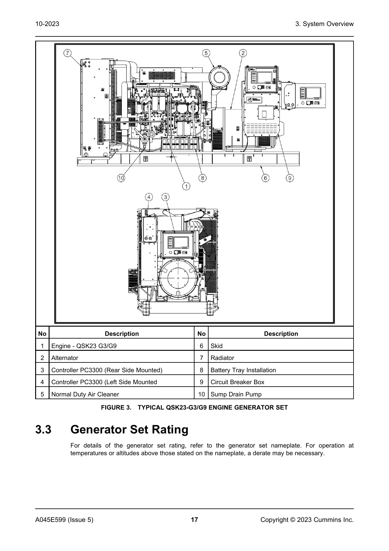
- 3. System Overview – generator set identification, nameplates for open and enclosed sets, generator set components, engine, sensors, pyrometers and pyrometer position, system options including battery charger, fuel tank, heaters, relays and motorised circuit breaker
- 4. Installation Overview – application and installation, safety considerations, standby heating devices, product modifications, derating factors
- 5. Specifications – generator set specifications and engine fuel consumption tables for 50 Hz and 60 Hz operation
- 6. Installing the Generator Set – transportation, location, moving the generator set, rigging instructions, mounting, vibration isolator installation and adjustment procedure (for IGB), access to the generator set, long-term storage
- 7. Mechanical Connections – fuel system, fuel return restrictions, fuel line connections, engine fuel connections, supply tank, fuel inlet pressure/restriction limit, fuel additives, exhaust system, ventilation and cooling, vents and ducts, dampers, air inlet and outlet openings
- 8. DC Control Wiring – digital connections, relay connections, PowerCommand 3.3 customer connections (configurable outputs, remote start, configurable inputs, remote emergency stop), ground fault relays, ground fault relay installation
- 9. AC Electrical Connections – transfer switch, alternator voltage connections, load connections, generator set load cable installation, cabling through gland plates, distribution cables, enclosure light, s-CAN network cable installation, load balancing, current transformers, coolant heater, alternator heaters, control box heater, battery commissioning, battery charger, grounding
- 10. Pre-Start Preparation – initial pre-start checks, electrical system, battery connections, site-specific configuration, starting
- 11. Installation Checklist – general items, generator set position, cooling air flow, diesel fuel system, gaseous fuel system, exhaust system, AC and DC wiring, pre-start items
- 12. Manufacturing Facilities – how to obtain service
- Appendix A – Alternator Reconnect Drawing: 0625-3100 reconnect drawing for HC alternator
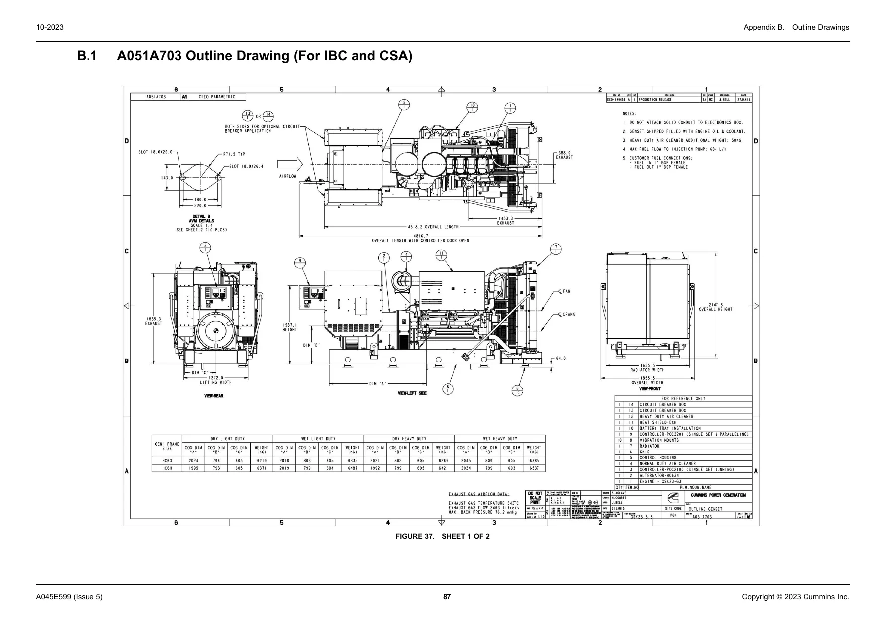
- Appendix B – Outline Drawings: A051A703 (for IBC and CSA), A064F343 (enclosed genset), A066H639 (open genset)
- Appendix C – Wiring Diagrams: A050R932 with PowerCommand 3.3 control, A051C423 control box heater, 0625-3100 generator reconnect, 0630-2727 fuel pump DOL starter, 0630-3216 fuel level customer connections, 0630-3217 thermal trip, 0630-2934 schematic, 0630-2935 schematic
This Cummins QSK23 installation manual goes far beyond basic mounting instructions. It provides the commissioning engineer with the complete mechanical and electrical connection detail required to bring a QSK23-G3/G9 generator set safely into service – including the fuel restriction limits, exhaust back pressure values, cooling airflow requirements, cable gland plate rules, s-CAN network termination details and battery commissioning sequence that determine whether the installation meets specification. The wiring diagram appendix alone spans multiple drawing sheets covering PowerCommand 3.3 control, control box heater, generator reconnect, fuel pump starter and customer input interfaces.
What This Installation Manual Enables You to Do
- Correctly plan the generator set location – level mounting surface tolerances, clearances, airflow requirements, exhaust routing and drainage.
- Safely transport, lift and rig the generator set using approved lifting points, spreader bars and angle limits for both open and enclosed sets.
- Mount the bedframe with the correct bolt size, washer and pipe arrangement, and install vibration isolators to the specified torque.
- Design and connect the fuel system with the correct flexible hoses, shutoff valves, strainer mesh, return line restrictions and inlet pressure limits.
- Install the exhaust system with approved thimbles, flexible sections, condensation traps, muffler supports and back pressure limits.
- Wire the PowerCommand 3.3 control – configurable outputs, remote start, configurable inputs, remote emergency stop and ground fault relay connections.
- Make AC load connections correctly, including alternator voltage reconnection, gland plate selection, trefoil cable grouping and load balancing to within 10 percent of median value.
- Install and terminate the s-CAN network cable for multi-set MLD control configurations, up to 16 generators and 200 m total network length.
- Commission and connect the battery, battery charger, coolant heater, alternator heater and control box heater.
- Ground and bond the generator set correctly whether the neutral is bonded at the set, at a 3-pole ATS or at a 4-pole ATS.
- Work through the full installation checklist before first start to confirm no items are missed.
Why This Manual Matters
Generator set installation errors are expensive and dangerous. Incorrect fuel line sizing, wrong exhaust back pressure, missing flexible sections, improper grounding, inadequate ventilation or incorrect battery commissioning can all cause failures that surface weeks or months later – after warranty coverage is affected by a non-compliant install. The Cummins QSK23 installation manual puts the exact limits, tolerances, torque figures and wiring pinouts in front of the installer before the work begins. It is written for the commissioning engineer who needs a single reference for the whole install, not a general guide that leaves the critical numbers out.
Instant PDF Delivery
This Cummins QSK23-G3/G9 installation manual is delivered as an instant PDF download after payment. No shipping, no waiting for a physical book, no risk of a lost or damaged copy. The file can be viewed on any laptop, tablet or smartphone, printed for the site office, and searched by keyword. Whether you are installing a C825 D5 in a plant room or commissioning a C900 D5e in an enclosure, having the complete A045E599 Issue 5 manual on hand means the correct procedure is never more than a page away.
Reviews
There are no reviews yet.