
Cummins QST30 Series Engine Service Manual 2006 – Volume 1 PDF Download
Original price was: $59.95.$39.95Current price is: $39.95.
Complete Cummins QST30 Series Engine Service Manual Volume 1 covering engine identification, familiarization, troubleshooting, complete engine disassembly and assembly, cylinder block, cylinder head, rocker levers, cam followers, fuel system, and injectors. Bulletin 4021539, 738 pages.
Description
File Details
- Manual type: Service Manual (Volume 1)
- Brand: Cummins
- Model: QST30 Series Engine
- Language: English
- Page count: 738
- File format: PDF
- Document number: Bulletin 4021539
- Date: 10-JANUARY-2006
Overview
The Cummins QST30 Series Engine Service Manual Volume 1 is the primary reference for technicians performing repair and rebuild work on QST30 engines. This 738-page volume opens with the engine identification and familiarization material, then moves into the full troubleshooting symptom charts and the complete engine removal, disassembly, and assembly groups. From there it covers the cylinder block, cylinder head, rocker levers, cam followers and tappets, fuel system, and injectors and fuel lines in dedicated group sections. Every procedure is written for the technician working on the engine, with torque values, wear limits, special tool references, and component illustrations placed alongside the disassembly, inspection, and assembly steps.
Chapters Covered
- Introduction
- Engine Identification (Section E)
- Familiarization (Section F)
- Troubleshooting Symptoms (Section TS)
- Complete Engine – Group 00
- Engine Disassembly – Group 00
- Engine Assembly – Group 00
- Cylinder Block – Group 01
- Cylinder Head – Group 02
- Rocker Levers – Group 03
- Cam Followers/Tappets – Group 04
- Fuel System – Group 05
- Injectors and Fuel Lines – Group 06
Introduction and Engine Identification
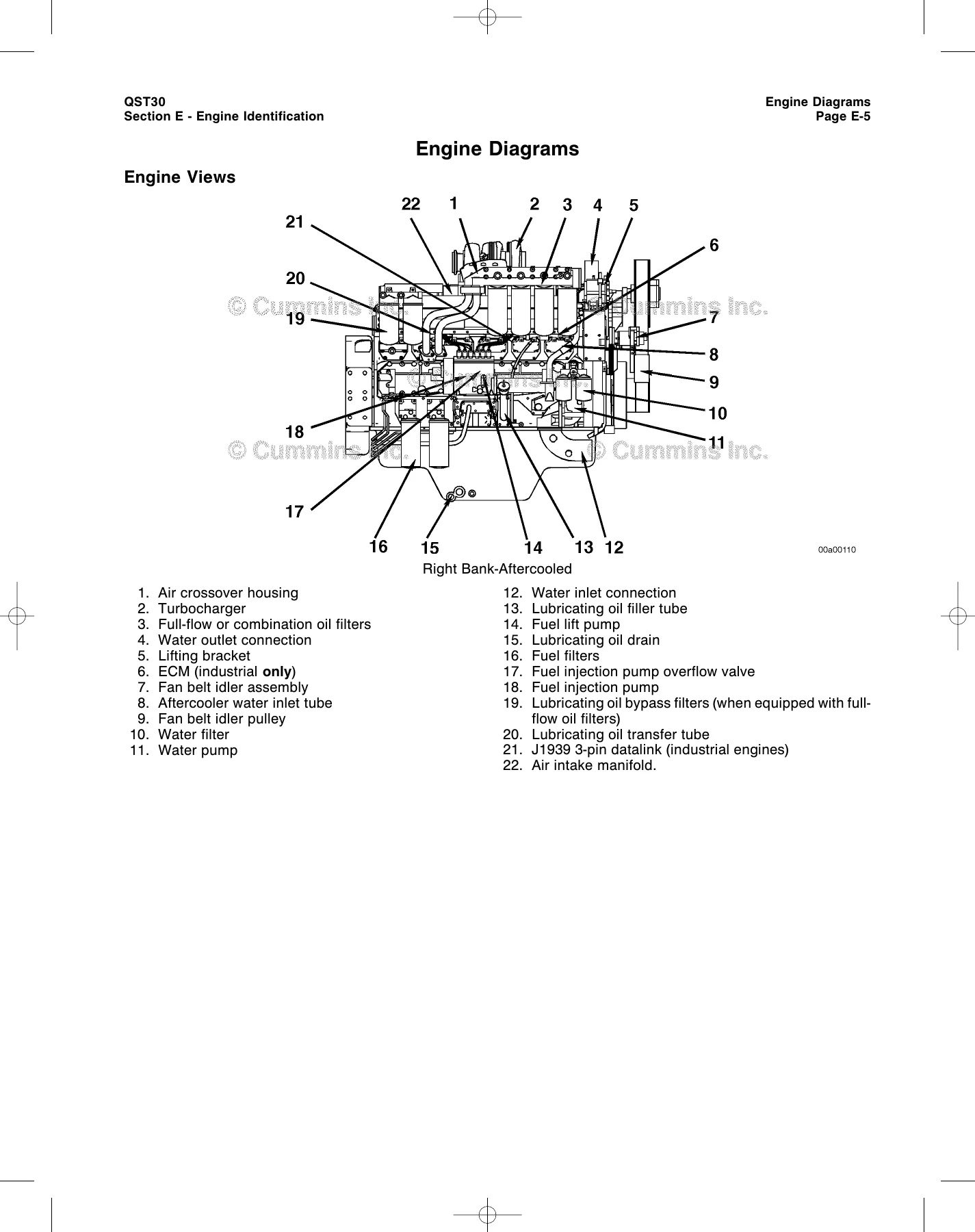
The opening sections lay out the manual’s structure, safety instructions, and the Cummins engine nomenclature used throughout. The engine identification section explains how to read the engine dataplate, the ECM dataplate, and the Bosch fuel injection pump dataplate, and provides the engine views and diagrams for both aftercooled and charge air cooled configurations.
Familiarization
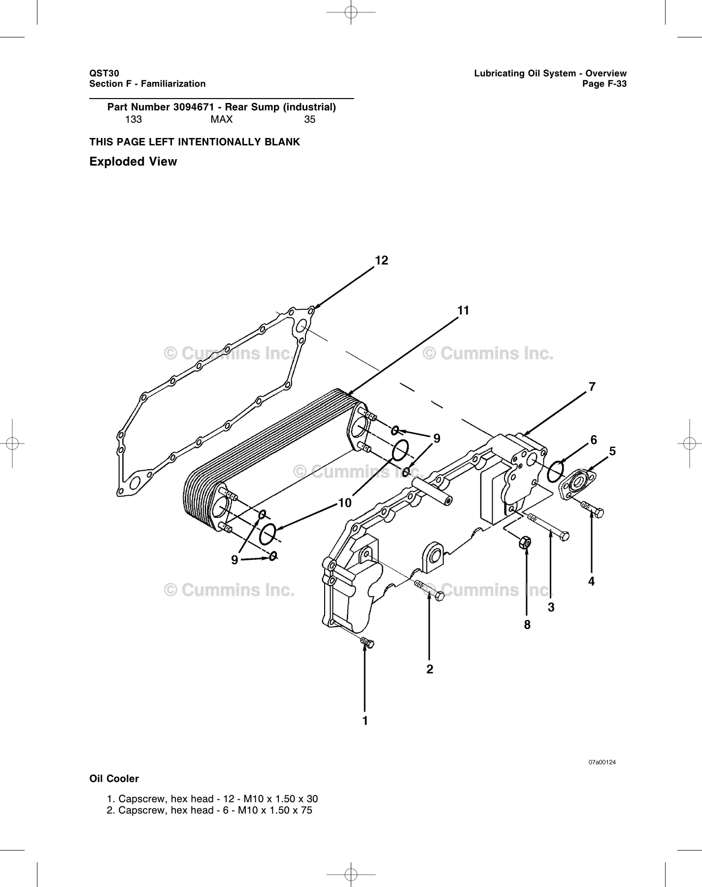
This section gives an overview of each major engine system before the technician reaches the repair procedures. It covers the air intake system, cooling system, compressed air system, electrical equipment, exhaust system, fuel system, and lubricating oil system with exploded views and flow diagrams. The flow diagrams are particularly useful for understanding how fuel, coolant, oil, and air move through the engine before diagnosing a problem.
Troubleshooting Symptoms
The troubleshooting section is built around symptom trees that guide the technician from the complaint to the correction. It covers air compressor problems, alternator charging issues, coolant loss and temperature problems, crankcase blowby, engine acceleration and power complaints, hard starting, rough running, excessive noise, smoke, fuel consumption, oil pressure and consumption, and more. Each symptom tree lists probable causes in order of simplicity and points to the procedure number for the repair.
Complete Engine – Group 00
This group covers engine removal and installation, long-term storage, and steam cleaning. The removal and installation procedures include the weight of the engine, the lifting fixture part number, and the steps for disconnecting fuel, coolant, electrical, and air connections before lifting the engine out of the chassis.
Engine Disassembly and Engine Assembly – Group 00
The disassembly and assembly sections are the core of the Volume 1 manual. The disassembly section runs through removing the accessory drive, aftercooler, air compressor, alternator, cam followers, camshaft, bearings, cylinder head, cylinder liner, fuel injection pumps, piston and connecting rod assemblies, and more. The assembly section mirrors the disassembly with the installation steps, torques, and clearance checks. Main bearing capscrew tightening is a three-step torque-to-yield sequence with a 90-degree turn, and the connecting rod capscrews follow a similar staged sequence with a 105-degree turn. Both sections include the special tool numbers needed for the job.
Cylinder Block – Group 01
This group covers the cylinder block, cylinder liner, piston, piston rings, connecting rod, crankshaft, main bearings, thrust bearings, camshaft and camshaft bushings, front gear cover and gear housing, idler gears, and vibration damper. The liner installation procedure includes the Three-Bond 1215 sealant application, liner protrusion measurement, and service shim selection. Bearing reuse guidelines and wear limits are given for connecting rod, main, and thrust bearings.
Cylinder Head – Group 02
The cylinder head group covers removal, cleaning, inspection, installation, and leak testing. It includes valve depth measurement, crack inspection limits for the injector bore, cylinder head flatness limits, and the capscrew free-length check for the torque-to-yield head capscrews. Valve removal and installation with the valve spring compressor are covered, along with injector protrusion measurement.
Rocker Levers – Group 03
This group covers the overhead set adjustment, rocker lever assembly, rocker lever cover, and rocker lever housing. The overhead set procedure includes the valve adjustment chart, the firing order (1R-1L-5R-5L-3R-3L-6R-6L-2R-2L-4R-4L), crosshead adjustment, and the intake and exhaust valve lash specifications. The rocker lever assembly inspection covers shaft and bushing measurements and wear limits.
Cam Followers/Tappets – Group 04
The cam follower group covers removal, inspection, and installation of the cam follower assemblies and push rods. It includes the specially drilled capscrew torque value, the cam follower roller clearance measurements, and the push rod inspection criteria for wear on the ball and socket ends.
Fuel System – Group 05
The fuel system group covers the in-line fuel injection pumps, fuel lift pump, fuel shutoff valve, fuel pump overflow valve, banjo connectors, and the EHAB device. The fuel injection pump section covers the open-drive and flange-mount pump configurations, removal and installation with the engine timed to the specified injection timing, and spline adapter service. The EHAB device section explains its function on industrial engines and includes the resistance test.
Injectors and Fuel Lines – Group 06
The injectors and fuel lines group covers air-in-fuel testing, fuel drain line restriction testing, fuel drain lines, fuel filter and filter head, fuel manifold, fuel supply lines, and injector removal and installation. The injector procedure includes the o-ring and seal ring installation, the hold-down clamp torque, and the connector tube and locknut torques.
Key Technical Content
Beyond the chapter coverage, this QST30 service manual includes a camshaft reuse guideline bulletin (3666052-02) with visual inspection criteria for polishing, denting, frosted bands, galling, pitting, and macro-spalling. The galling width limits differ between standard engines and the injector camshafts on ISX, Signature, QSX15, and ISX with CM870 controller engines. The manual also contains the engine dataplate locations, the ECM dataplate layout for industrial and generator-drive applications, and the Bosch fuel injection pump dataplate information.
Who This Manual Is For
This Volume 1 service manual is written for the diesel technician, fleet shop, and rebuild facility working on QST30 engines in construction, generator drive, generator set, fire pump, locomotive, marine, power unit, and railcar applications. The procedures assume the engine or component is removed from the chassis, and some steps call for Cummins special service tools. The manual covers the engine and its components, not the vehicle or equipment chassis systems, so the OEM manual is still needed for chassis-side work.
Get the Complete QST30 Service Manual
Having the Cummins QST30 Series Engine Service Manual Volume 1 on hand means you can follow the factory procedure for engine removal, teardown, inspection, assembly, and installation instead of working from memory or guesswork. The torque sequences for main bearings, connecting rods, and cylinder heads are torque-to-yield specifications, and getting them wrong can damage the engine. The troubleshooting symptom trees help you trace a complaint to the right repair without replacing parts on suspicion. This PDF is delivered instantly after purchase, with no shipping and no waiting. Open it on a laptop, tablet, or phone in the shop, or print the pages you need for the job. The 738-page manual is organized by group and section so you can go straight to the system you are working on.
IMAGES PREVIEW
Reviews
There are no reviews yet.