Daewoo Doosan Forklift BC15T to BC20T Service Manuals SB2162E01 – PDF DOWNLOAD
$29.95
Daewoo Doosan Forklift BC15T to BC20T Service Manuals SB2162E01 – PDF DOWNLOAD
Description
Daewoo Doosan Forklift BC15T to BC20T Service Manuals SB2162E01 – PDF DOWNLOAD
FILE DETAILS:
Daewoo Doosan Forklift BC15T to BC20T Service Manuals SB2162E01 – PDF DOWNLOAD
Language :English
Pages :415
Downloadable : Yes
File Type : PDF
IMAGES PREVIEW OF THE MANUAL:
DESCRIPTION:
Daewoo Doosan Forklift BC15T to BC20T Service Manuals SB2162E01 – PDF DOWNLOAD
SAFETY
Theservicemanormechanicmaybe unfamiliar with many of the systems on this machine. This makes it important to use caution when performing service work. A knowledge of the system and/or components is important before the removal or disassembly of any component. Because of the size of some of the machine components, the serviceman or mechanic should check the weights noted in this Manual, Use proper lifting procedures when removing any components. Following is a list of basic precautions that should always be observed.
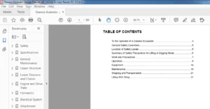
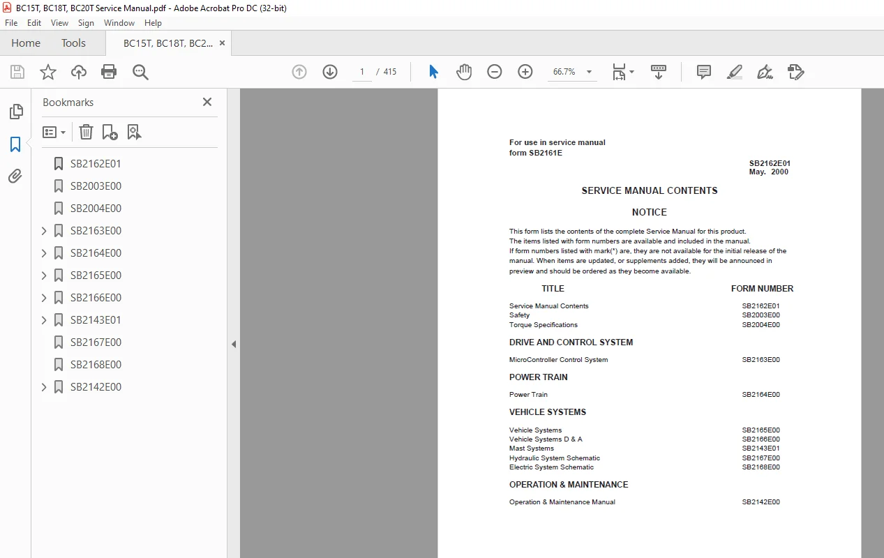
TABLE OF CONTENTS:
Daewoo Doosan Forklift BC15T to BC20T Service Manuals SB2162E01 – PDF DOWNLOAD
Service Manual Contents SB2162E01
Safety SB2003E00
Torque Specifications SB2004E00
DRIVE AND CONTROL SYSTEM
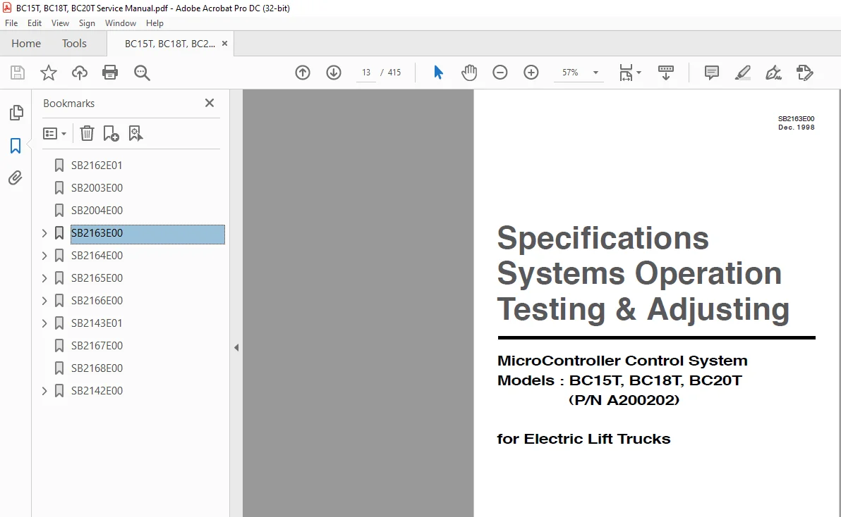
MicroController Control System SB2163E00
POWER TRAIN
Power Train SB2164E00
VEHICLE SYSTEMS
Vehicle Systems SB2165E00
Vehicle Systems D & A SB2166E00
Mast Systems SB2143E01
Hydraulic System Schematic SB2167E00
Electric System Schematic SB2168E00
OPERATION & MAINTENANCE
Operation & Maintenance Manual SB2142E00
SB2162E01 1
SB2003E00 3
SB2004E00 5
SB2163E00 13
Index 17
Specifications 19
Component measurements 19
Contactors 19
Control Panel (Layout) 23
Current Measurements 19
Direction & Accelerator 22
Display Layout 21
Introduction to Mosfet 20
Mosfet (transistor) module connections 20
Mosfet (transistor) module measurements 20
Systems Operation 36
Accessory Circuits 36
DC- DC Converter 36
Hour Meter Circuit 36
Actuation Circuit 37
Drive Circuit 43
Bypass Circuit 45
Electrical Braking (Plugging) 45
Steering Circuit 47
Thermal Protection Circuits 46
General Information 32
Glossary 25
Hydraulic Pump Motor Circuit 39
Lift Bypass Circuit 42
Lift Control Circuit 41
Power Steering Circuit 40
Tilt and Auxiliary Control Circuit 42
Location of Control Panel Components 30
Logic Unit 32
Operational Circuit Elements 34
Accelerator Control 36
Battery Discharge Indicator (BDI) 34
Central Vehicle Monitoring System 34
Contactors 36
Current Sensor (Shunts) 36
On Board “Run Time” Diagnostics(Fault Detection) 34
Resistor (Charging) 36
Wait Mode 36
Power Module (Layout) 31
Program Features 48
Returning to Default Settings 49
Symbol Library 29
Testing And Adjusting 55
Built – In Diagnostic Operation 55
Accessing Stored Error Codes 56
“Run – Time” Diagnostics(Lift Truck in Operation) 55
“Self” Diagnostics(Lift Truck in Operation) 56
Component Tests106
Accelerator Control108
Capacitor (Head)Central Vehicle Monitoring System108
Self Test108
Conductor and Switch Continuity108
Contactor (Bypass Activation)108
Contactor Components109
DC-DC Converter109
Diode Replacement110
Diodes109
Logic Unit Quick Reference Voltage Check106
Mosfet Module Replacement110
Resistor (Charging)111
Thermal Switch111
Control and Power System Operational Checks 53
Electrical System Adjustments112
Battery Discharge Indicator (BDI)Adjustment113
Current Limit Test and Adjustment115
Electrical Braking (Plugging)115
Parking Brake Switch112
Tilt and Auxiliary Speed Adjustment112
Tilt and Auxiliary Switches112
Preparation Tests and Checks 51
System Tests and Adjustments103
Discharging Head Capacitor(HEAD CAP)103
Logics Removal104
“Run Time” Tests104
Test Equipment103
Troubleshooting 50
Troubleshooting Check List 50
Troubleshooting Problem List 57
SB2164E00116
Index120
Specifications128
Brake128
Drive Motor124
Final Drive125
General Tightening Torques122
Motor and Transmission127
Wheel Mounting126
Systems Operation130
Drive Motor130
Final Drive131
General Information129
Testing And Adjusting145
Brake145
Connecting the brake cable145
Connecting the hydraulic brake system145
Replenishing With Transmission Fluid145
Drive Motor137
Armature Terminal Test141
Armature Tests138
Brush Holder Test142
Brush Life Estimate142
Commutator Inspection140
Field Coil and Terminal Tests141
Motor Brushes137
Thermal Switch Tests143
Motor and Transmission143
Motor Transmission Unit and Vehicle Frame144
Troubleshooting132
Checks During Operation132
Drive Motor132
Transmission136
Visual Checks132
Disassembly And Assembly146
Drive Axle146
SB2165E00157
Index161
Specifications163
Hydraulic Control Valve163
Hydraulic Pump164
Hydraulic Pump Motor171
Lift Cylinders165
Standard165
Full Free Triple Lift and Full Free Lift Primary165
Full Free Lift Secondary166
Full Free Triple Lift Secondary166
Sideshift Cylinder164
Steer Axle And Wheel170
Steering Gear169
Steering Wheel168
Tilt Cylinders167
Systems Operation184
Brake System184
Master Cylinder184
Electric Motor185
Hydraulic Pump Motor185
Hydraulic System172
Basic Hydraulic Schematic172
Control Valve174
Steering System181
Steering System Schematic181
Steering Gear182
Testing and Adjusting199
Brake System199
Brake System Air Removal199
Parking Brake Control Group Adjustment201
Parking Brake Test201
Pedal Adjustment200
Hydraulic Pump Motor201
Armature Tests203
Brush Holder Test206
Brush Life Estimate206
Commutator Inspection204
Field Coil And Terminal Tests205
Motor Brushes201
Hydraulic System196
Lift Cylinder Air Removal197
Relief Valve Pressure Check196
Steering System198
Steer Wheel Bearing Adjustment198
Steering System Air Removal198
Steering System Pressure Check199
Troubleshooting186
Brake System191
Hydraulic Motor192
Hydraulic System and Mast186
Steering System190
Visual Checks186
SB2166E00207
Index211
Brake Master Cylinder245
Control Panel254
Counterweight269
Drive Axle259
Drive Motor & Drive Axle256
Hood(with seat) Assembly213
Hydraulic Control Valve Switch Group 215
Hydraulic Control Valve216
Hydraulic Pump225
Hydraulic Pump Motor223
Overhead Guard214
Primary Lift Cylinder230
Secondary Lift Cylinder228
Slave Logic Board227
Spindle-Steer Axle251
Steer Axle246
Steer Sensor Group235
Steering Column236
Steering Unit238
Steering Wheel236
Tilt Cylinder231
SB2143E01270
Index274
Disassembly & Assembly276
Forks276
Backrest276
Carriage277
Mast280
Testing & Adjusting293
Carriage Adjustment293
Chain Adjustments294
Chain Wear Test294
Carriage and Mast Height Adjustment295
Forks Parallel Check295
Tilt Cylinder Alignment296
Drift Test296
Tilt Cylinder Adjustment297
Lift & Tilt Mounting Group Adjustment298
Mast mounting Group Adjustment299
SB2167E00300
SB2168E00302
SB2142E00304
Contents306
S.M 19 /2/2025