Daewoo Doosan Solar 140LC-V Excavator Service Manual – PDF DOWNLOAD
Original price was: $45.95.$20.95Current price is: $20.95.
Daewoo Doosan Solar 140LC-V Excavator Service Manual – PDF DOWNLOAD
Solar 130LC-V 0001 and Up
Solar 170LC-V 1001 and Up
Solar 220LC-V 0001 and Up
Solar 220N-V 1001 and Up
Solar 250LC-V 1001 and Up
Solar 290LC-V 0001 and Up
Solar 300LC-V 1001 and Up
Solar 300LL 1001 and Up
Solar 330LC-V 1001 and Up
Solar 340LC-V 1001 and Up
Solar 400LC-V 1001 and Up
Solar 420LC-V 1001 and Up
Solar 450LC-V 1001 and Up
Solar 470LC-V 1001 and Up
Description
Daewoo Doosan Solar 140LC-V Excavator Service Manual – PDF DOWNLOAD
DESCRIPTION:
Daewoo Doosan Solar 140LC-V Excavator Service Manual – PDF DOWNLOAD
GENERAL SAFETY ESSENTIALS:
ACCESSORY APPLICATIONS:
The excavator has been primarily designed for moving earth with a bucket. For use as a grapple or for other object handling, contact Daewoo for proper installation and application. Lifting-work applications (unless restricted or prohibited by local regulations) are permitted in approved lift configuration, to rated capacity only, with no side-loading. DO NOT use the machine for activities for which it was not intended. DO NOT use the bucket for lifting work, unless lift slings are used in the approved configuration. Use of an accessory hydraulic hammer (breaker), work in rough terrain, demolition applications or other hazardous operation may require installation of additional protective structures to safeguard the operator.
LIFTING CAPACITY RATING CONFIGURATION:
Lifting capacity ratings that are printed at the end of this safety section are based on the machine being level, on a firm supporting surface, with hooks and slings attached in approved configuration. Loads must be balanced and supported evenly. Use taglines to keep the load steady if wind conditions and large surface area are a problem. Work crew hand signals, individual tasks and safe procedures should all be universally understood before the lift is made.
TABLE OF CONTENTS:
Daewoo Doosan Solar 140LC-V Excavator Service Manual – PDF DOWNLOAD
Safety..................................................................................  1
	Track Excavator Safety..............................................................  2
Specifications.......................................................................... 24
	Specifications for Solar 300LC-V.................................................... 25
		General Description............................................................. 27
		Component Locations............................................................. 28
		General Dimensions.............................................................. 31
		Working Range................................................................... 32
		General Specifications.......................................................... 34
		Engine Performance Curves (Per KS-R1004 Standard)............................... 36
		Approximate Weight of Workload Materials........................................ 38
		Performance Tests............................................................... 41
		Excavator Performance Standards................................................. 42
General Maintenance..................................................................... 47
	General Maintenance Procedures...................................................... 48
		Welding Precautions and Guidelines.............................................. 50
		Hydraulic System - General Precautions.......................................... 51
		Maintenance Service and Repair Procedure........................................ 52
		Hydraulic System Cleanliness and Oil Leaks...................................... 53
		Cleaning and Inspection......................................................... 54
	Standard Torques.................................................................... 62
		Torque Values for Standard Metric Fasteners..................................... 64
		Torque Values for Standard U.S. Fasteners....................................... 65
		Type 8 Phosphate Coated Hardware................................................ 67
		Torque Values for Hose Clamps................................................... 68
		Torque Values for Split Flanges................................................. 69
		Torque Wrench Extension Tools................................................... 70
Upper Structure......................................................................... 74
	Cab................................................................................. 75
		Removal......................................................................... 77
		Installarion.................................................................... 80
	Counterweight....................................................................... 83
		General......................................................................... 85
		Removal......................................................................... 87
		Installation.................................................................... 88
	Fuel Tank........................................................................... 89
		General Description............................................................. 91
		Removal......................................................................... 94
		Installation.................................................................... 98
		Start-up Procedures.............................................................100
	Fuel Transfer Pump..................................................................101
		General Description.............................................................103
		Troubleshooting.................................................................104
		Replacement of Rotor and Vane...................................................104
		Replacement of Rear Cover.......................................................105
		Replacement of Armature.........................................................106
	Swing Bearing.......................................................................107
		Swing Bearing Maintenance.......................................................109
	Swing Reduction Gear (M105).........................................................113
		General Description.............................................................115
		Special Tools and Materials.....................................................118
		Troubleshooting, Testing and Adjustment.........................................121
		Removal.........................................................................122
		Disassembly.....................................................................123
		Reassembly......................................................................128
		Installation....................................................................133
		Start-up Procedures.............................................................134
Lower Structure and Chassis.............................................................135
	Track Assembly......................................................................136
		General Description.............................................................138
		Track Tension...................................................................138
		Cleaning and Inspection (Wear Limits and Tolerances)............................140
		Track Shoes and Links...........................................................144
		Front Idler Roller..............................................................146
		Lower Roller....................................................................150
		Upper Roller....................................................................154
		Track Spring and Track Adjusting Cylinder.......................................159
Engine and Drive Train..................................................................162
	Air-conditioner.....................................................................163
		Refrigerant Circulation.........................................................165
		Control Panel...................................................................167
		Air Discharge According to Path Selection.......................................170
		Air-conditioning System Circuit Diagram.........................................172
		Troubleshooting.................................................................174
		Refrigerant System Repairs......................................................177
	Drive Coupling (Main Pump)..........................................................185
		Drive Coupling..................................................................187
		Special Tools...................................................................188
Hydraulics..............................................................................195
	Hydraulic System Troubleshooting, Testing and Adjustment............................196
		Hydraulic System-General Notes..................................................199
		Hydraulic Schematic.............................................................200
		Operation of Working Components.................................................201
		Procedural Troubleshooting Baseline Recommendations.............................205
		Pilot Pressure..................................................................206
		Power Mode Valve................................................................207
		Swing Priority Valve............................................................208
		Pressure Up Valve...............................................................209
		Pump Input Power Control........................................................210
		Flow Meter and Flow Meter Kit Installation and Testing..........................212
		Swing System Troubleshooting....................................................213
		Troubleshooting-Swing Gearbox...................................................215
		Troubleshooting-Hydraulic Problems..............................................217
		Troubleshooting-Control Valve...................................................218
		Troubleshooting-Travel Control Valve............................................219
		Troubleshooting-Joystick Control Valve..........................................220
	Accumulator.........................................................................222
		General Description.............................................................224
	Center Joint (Swivel)...............................................................226
		General Description.............................................................228
		Troubleshooting, Testing and Adjustment.........................................230
		Disassembly.....................................................................231
		Reassembly......................................................................231
	Cylinders...........................................................................234
		General Description.............................................................236
		Special Tools and Materials.....................................................239
		Disassembly.....................................................................243
		Reassembly......................................................................249
	Swing Motor (Toshiba MFC200)........................................................254
		General Description.............................................................256
		Special Tools and Materials.....................................................266
		Troubleshooting, Testing and Adjustment.........................................267
		Removal.........................................................................269
		Disassembly.....................................................................270
		Cleaning and Inspection (Wear Limits and Tolerances)............................275
		Reassembly......................................................................275
		Installation....................................................................282
		Start-up Procedures.............................................................283
	Travel Motor (With Gearbox).........................................................284
		General Description.............................................................286
		Troubleshooting, Testing and Adjustment.........................................304
		Disassembly.....................................................................307
		Cleaning and Inspection (Wear Limits and Tolerances)............................315
		Reassemby.......................................................................319
		Installation....................................................................332
	Main Pump (Kawasaki)................................................................334
		Swash Plate Tyoe K5V Series Axial Piston Pump...................................337
		Regulator for K5V, K3V Series of Kawasaki Swash Plate Type Axial Piston Pump....360
	Main Control Valve (Kayaba).........................................................382
		General Description.............................................................384
		Trobleshooting, Testing and Adjustement.........................................418
		Disassembly.....................................................................421
		Cleaning and Inspection (Wear Limits and Tolerances)............................427
		Reassembly......................................................................428
		Installation....................................................................435
		Start-up Procedures.............................................................435
	Pilot Control Valve (Work Lever/Joystick)...........................................436
		General Description.............................................................438
		Removal.........................................................................441
		Disassembly.....................................................................444
		Cleaning and Inspection (Wear Limits and Tolerances)............................448
		Reassembly......................................................................449
		Installation....................................................................454
		Start-up Procedures.............................................................455
	Travel Control Valve (With Damper)..................................................456
		General Description.............................................................458
		Troubleshooting, Testomg amd Adjustment.........................................463
		Removal.........................................................................464
		Disassembly.....................................................................466
		Cleaning and Inspection (Wear Lmits and Tolerances).............................472
		Reassembly......................................................................473
		Installation....................................................................478
		Start-up Procedures.............................................................479
	Hydraulic Schematic (S300LC-V)......................................................480
		General Description.............................................................482
		Solar 300LC-V...................................................................483
Electrical System.......................................................................486
	Electrical System...................................................................487
		Troubleshooting - Electrical System.............................................490
		Overview........................................................................491
		Electric Supply System..........................................................492
		Engine Starting Circuit.........................................................493
		Engine Preheating System........................................................495
		Engine Stop System..............................................................496
		Charging System.................................................................499
		Monitoring System...............................................................500
		Operation.......................................................................504
		Warning and Indicator Lights....................................................506
		Initial Operation...............................................................508
		Mode Select Switch..............................................................509
		Graphic Information Area Display................................................510
		Main Menu.......................................................................512
		Special Menu....................................................................514
		Electronic Hydraulic Control System (e-EPOS)....................................528
		Power Mode Control..............................................................530
		Power Mode Control - Circuit Diagram............................................534
		Trenching Mode Control..........................................................536
		Trenching Mode Control - Circuit Diagram........................................538
		Engine Control System...........................................................539
		Engine Control Motor............................................................540
		Engine Control Dial.............................................................541
		Engine Control Circuit Diagram..................................................543
		Automatic Deceleration Control (Auto Idle Control)..............................544
		Engine Overheat Protection System...............................................545
		Power Boost Mode................................................................546
		Automatic Travel Speed Control..................................................548
		Engine Control Device - Adjustment..............................................550
		Self-diagnostic Function........................................................553
		Engine Throttle Controller......................................................555
		Wiper System....................................................................556
		Lighting System.................................................................558
		Overload Warning Device.........................................................560
	Electrical Schematic (S300LC-V).....................................................561
		General Description.............................................................563
		Solar 300LC-V...................................................................564
Attachment..............................................................................567
	Boom and Arm........................................................................568
		Front Attachment Pin Specifications.............................................570
		Front Attachment-Removal and Installation.......................................571
		Installation....................................................................574
		Start-up Procedures.............................................................575
	Bucket..............................................................................576
		Bucket Tooth Inspection and Replacement.........................................578
		Bucket O-ring Replacement.......................................................581
		Bucket Shimming Procdures.......................................................583
		Bucket Attachment, Removal and Reversal.........................................584
DAEWOO DOOSAN SOLAR 140LC-V EXCAVATOR SERVICE MANUAL – PDF DOWNLOAD:
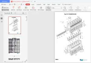
IMAGES PREVIEW OF THE MANUAL:
PLEASE NOTE:
- This is not a physical manual but a digital manual – meaning no physical copy will be couriered to you. The manual can be yours in the next 2 mins as once you make the payment, you will be directed to the download page IMMEDIATELY.
- This is the same manual used by the dealers inorder to diagnose your vehicle of its faults.
- Require some other service manual or have any queries: please WRITE to us at [email protected]
H Colten –
Great access