Daewoo Doosan Forklift D50A-2, D60A-2, D70A-2 Service Manual SB4024E00 – PDF DOWNLOAD
$28.95
Daewoo Doosan Forklift D50A-2, D60A-2, D70A-2 Service Manual SB4024E00 – PDF DOWNLOAD
Description
Daewoo Doosan Forklift D50A-2, D60A-2, D70A-2 Service Manual SB4024E00 – PDF DOWNLOAD
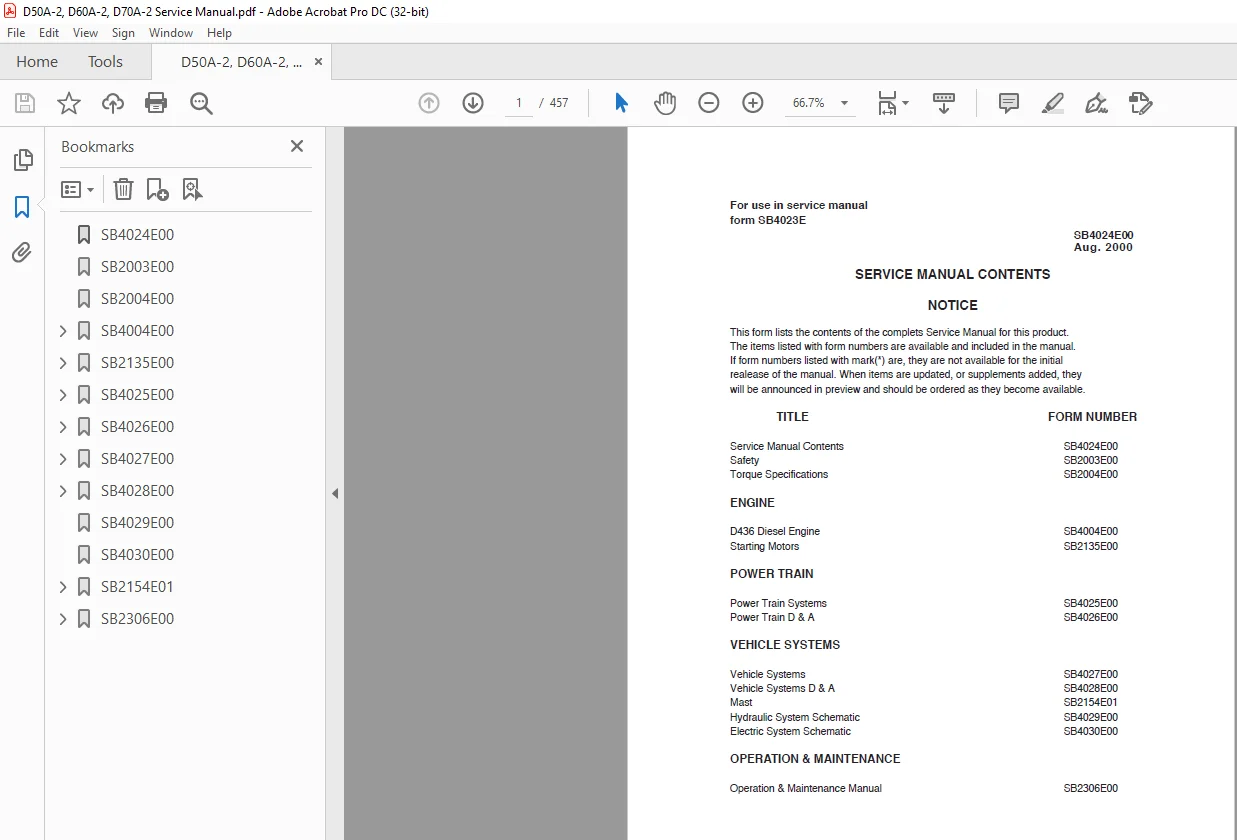
FILE DETAILS:
Daewoo Doosan Forklift D50A-2, D60A-2, D70A-2 Service Manual SB4024E00 – PDF DOWNLOAD
Language :English
Pages :457
Downloadable : Yes
File Type : PDF
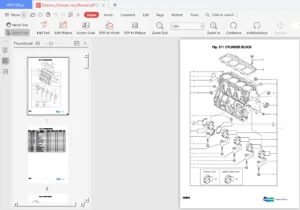
IMAGES PREVIEW OF THE MANUAL:
DESCRIPTION:
Daewoo Doosan Forklift D50A-2, D60A-2, D70A-2 Service Manual SB4024E00 – PDF DOWNLOAD
SAFETY
Theservicemanormechanicmaybe unfamiliar with many of the systems on this machine. This makes it important to use caution when performing service work. A knowledge of the system and/or components is important before the removal or disassembly of any component. Because of the size of some of the machine components, the serviceman or mechanic should check the weights noted in this Manual, Use proper lifting procedures when removing any components. Following is a list of basic precautions that should always be observed.
TABLE OF CONTENTS:
Daewoo Doosan Forklift D50A-2, D60A-2, D70A-2 Service Manual SB4024E00 – PDF DOWNLOAD
SB4024E00 1
SB2003E00 3
SB2004E00 5
SB4004E00 13
Index 17
Engine 19
Symptom-related diagnostic procedure 19
Specifications 20
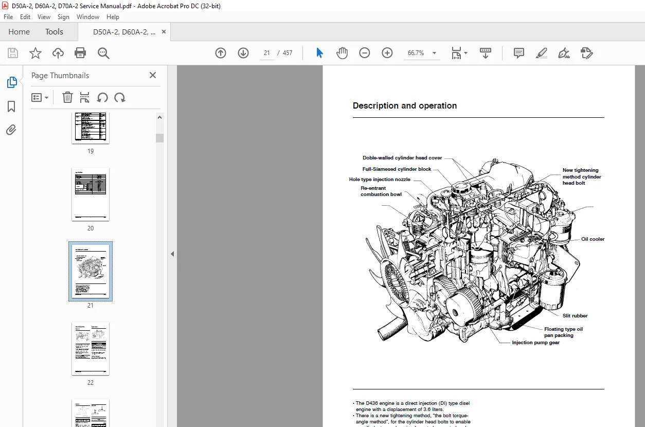
Description and operation 21
On-vehicle service 22
Engine oil 22
Engine coolant 22
Drive belt 23
Alternator drive belt 24
Valve clearance 24
Idle speed 25
Injection timing 25
Compression pressure 28
Disassembly, Inspection & reassembly procedure 29
Disassembly 29
Inspection 38
Reassembly 49
Lubrication System 62
Special service tools 62
Symptom-related diagnostic procedure 63
Specifications 63
Description and operation 64
On-vehicle service 65
Engine oil 65
Oil pressure 66
Removal and replacement procedure 67
Oil pump and Oil cooler 67
Disassembly, inspection and reassembly procedure 69
Oil pump 69
Oil cooler 71
Cooling System 73
Special service tools 73
Symptom-related diagnostic procedure 74
Specifications 74
Description and operation 75
On-vehicle service 76
Engine coolant 76
Radiator cap 77
Radiator 77
Removal and replacement procedure 78
Thermostat 78
Water pump 79
Disassembly, inspection and reassembly procedure 79
Water pump 79
Intake and exhaust System 82
Description and operation 82
Air heater system 82
On-vehicle service 87
Air heater system 87
Disassembly and reassembly procedure 90
Intake manifold 90
Exhaust manifold 91
Fuel System 92
Symptom-related diagnostic procedure 92
Specifications 93
Description and operation 94
On-vehicle service 96
Injection pump 96
Injection timing 97
Removal and replacement procedure101
Injection Pump101
Fuel stop system104
Fuel injection nozzle109
Disassembly, inspection and reassembly procedure111
Nozzle body and needle valve111
Starting System113
Symptom-related diagnostic procedure113
Specifications113
Description and operation114
On-vehicle service115
Starter115
Magnetic switch115
Wiring diagram116
Removal and replacement procedure117
Charging System119
Symptom-related diagnostic procedure119
Charging system119
Alternator120
Specifications121
Description and operation122
Charging system122
Alternator123
On-vehicle service125
Alternator125
Removal and replacement procedure126
SB2135E00127
Index131
Specifications133
Starting Motor133
Systems Operation135
Starting Motor135
Introduction135
Starting Motor Operation Diagrams138
Testing And Adjusting141
Starting Motor142
Off Machine No Load Test145
On Machine Starting Motor Diagnosis Procedure142
Starting Motor Component Tests146
Troubleshooting141
Troubleshooting Problem List141
Troubleshooting Problems141
Disassembly And Assembly151
Starting Motor151
Assemble Starting Motor154
Disassemble Starting Motor151
SB4025E00158
Index162
Specifications164
Brake Drum Diameter167
Differential165
Drive Axle165
General Tightening Torque164
Power Transfer Group167
Torque Converter165
Wheel Bearings And Drive Wheels166
Wheel Brakes166
Systems Operation168
Differential And Drive Axles189
Automatic Adjustment190
Differential189
Wheel Brake Components190
Wheel Hubs189
General Information168
Power Shift Transmission170
General Information170
Power Flow In High Speed Forward172
Power Flow In High Speed Reverse174
Power Flow In Low Speed Forward171
Power Flow In Low Speed Reverse173
Transmission Hydraulic Control System176
High Speed Forward181
High Speed Reverse185
Inching Valve Operation187
Low Speed Forward179
Low Speed Reverse183
Neutral Position177
Valve Function Chart188
Transmission Hydraulic System175
Transmission Lubrication System176
Transmission Pump, Filter, Torque Converter and Oil Cooler System176
Torque Converter169
Testing And Adjusting191
Converter Stall Test198
Inching Pedal Adjustment200
Transmission Pressure Tests196
Troubleshooting191
Check List During Operation191
Check List From Operation Noises193
Check List From Pressure Test194
Differential195
Transmission Electrical System Troubleshooting202
Visual Checks191
Wheel Brakes Adjustment199
SB4026E00205
Index209
Transmission222
Drive Shaft and Universal Joints211
Engine, Torque Converter and Transmission212
Engine, Torque Converter and Transmission Separation and Connection215
Torque Converter216
Torque Converter and Transmission214
Torque Converter,Disassemble & Assemble 217
Transmission Control Valve218
Transmission Control Valve,Disassemble & Assemble218
Transmission, Disassemble & Assemble222
Drive Axle239
Disassembly239
Removal and Strip Down Of The Axle Housing243
Removal and Strip Down Of The Brake242
Removal and Strip Down Of Wheel Hub239
Reassembly246
Adjustment Of Bearing Preload On Bevel Pinion Shaft248
Assembly Of Axle Housing Into Input Housing252
Contact Pattern Check252
Determination of Installation Dimension for Bevel Pinion Shaft247
Measurement Bearing Play Of Bevel Pinion Shaft248
Mounting Of Brake and Wheel Hub to The Axle Housing253
Preassembly Differential249
SB4027E00257
Index261
Specifications263
Hydraulic Control Valve263
Hydraulic Pump264
Steering Gear265
Steering Wheel And Gear Group265
Steer Wheels And Steer Axle265
Tilt Cylinder264
Tilt Cylinder Installation264
Systems Operation266
Brake System279
Control Valves268
Hydraulic System266
Steering System275
Steering Unit276
Testing And Adjusting280
Brake System291
Brake System Air Removal291
Parking Brake Adjustment292
Parking Brake Test292
Hydraulic System288
Steering System289
Tilt Cylinder Alignment293
Troubleshooting280
Brake System286
Hydraulic System and Mast281
Operation Checks280
Steering System285
Visual Checks280
SB4028E00294
Index298
Brake Hydraulic Booster314
Counterweight303
Hood303
Hydraulic Control Valve304
Hydraulic Oil Filter Assembly313
Hydraulic Pump310
Overhead Guard304
Seat304
Steer Axle314
Steering Column And Gear Assembly321
Steering Wheel320
Tilt Cylinders300
Tires And Rims (Steer)326
SB4029E00327
SB4030E00329
SB2154E01331
Index335
Disassembly & Assembly337
Carriage337
Carriage Rollers338
Mast340
Specifications343
Carriage343
Lift Chains343
Mast343
Systems Operations344
Lift Cylinder & Mast344
Testing & Adjusting345
Carriage Adjustment346
Chain Adjustment Check347
Chain Adjustment347
Chain Wear Test347
Cylinder Adjustment345
Drift Test349
Mast Adjustment345
Measurement Of Carriage And Forks348
Tilt Angle Check348
SB2306E00351
Table of Contents353
S.M 18/2/2025