Daewoo Doosan MG 400 -V ELECTRICAL SYSTEM manual – PDF DOWNLOAD
Original price was: $80.00.$28.95Current price is: $28.95.
Daewoo Doosan MG 400 -V ELECTRICAL SYSTEM manual – PDF DOWNLOAD
Description
Daewoo Doosan MG 400 -V ELECTRICAL SYSTEM manual – PDF DOWNLOAD
DESCRIPTION:
Daewoo Doosan MG 400 -V ELECTRICAL SYSTEM manual – PDF DOWNLOAD
OVERVIEW
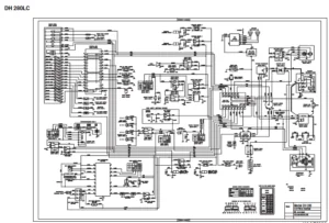
The electrical system for this equipment is DC 24 volts. The rated voltage for all electric components is 24 volts with the exception of the car stereo and the air-conditioning control actuator. The system contains two 12 volt batteries connected in series and a three phase AC generator with a rectifier. The electric wiring used in the system is easily identifiable by the insulator color. The color symbols used in the electric system is listed in the following chart
ELECTRIC SUPPLY SYSTEM
The electric power circuit supplies electric current to each electric component. It consists of a battery, battery relay, starter switch, circuit breaker, fusible link and fuse box. The negative terminal of the battery is grounded to the vehicle body.
Even when the starter switch is in the “OFF” position, electric current is supplied to the following components through battery, to the fusible link, and then to the fuse box.
1. Cabin lamp, fuel pump switch, No. 1 terminal of DC-DC converter (back up for car stereo memory).
2. “B” terminal of starter switch and No. 22 terminal of air-conditioner control panel.
3. Power terminal “B” of engine stop motor.
- When the starter switch is in the preheat, on and start positions, the current flows from the battery, to the fusible link, to the fuse box, to the starter switch “B” terminal/starter switch “BR” terminal, to the diode, and then to the battery relay “BR” terminal. which activates the coil of the battery relay and the electric supply system is energized.
- When the battery relay’s contacts are connected, all electric devices can be operated.
- While the engine is not running, the electric power for all electric devices are supplied by the battery. Once the engine is started the power is supplied from the alternator.
ENGINE STARTING CIRCUIT
OPERATION DURING START PROCESS
- When the starter switch is turned to the start position, the safety start relay (14) is opened by the current flow from the connected “52” and “67” terminal of the transmission controller (13) and the “S” and “E” terminal of the starter controller (7) are connected. At this time the contacts in the starter relay (8) are closed by the current flow from the battery (1), to the fusible link (3), to the “B” terminal of the starter switch (5), to the “C” terminal of the starter switch (5), to the “C” terminal of the starter relay (8), to the “D” terminal of starter relay (8), to the “S” terminal of starter controller (7), to the “E” terminal of the starter controller, and then to the ground.
- The contact point “B” and “PP” of starter relay (8) are connected, the pinion gear of the starter (9) is pushed forward and makes contact with the ring gear of the flywheel and the internal contacts of the starter are connected.
- The current flows from the battery (1), to the “A” terminal of the battery relay (2), to the “B” terminal of the battery relay (2), and then to the “B” terminal of the starter (9). The starter motor is rotated and the engine is started.
- The engine can be cranked only when the transmission selector switch (11) is the neutral position. If the transmission selector switch (11) is in the forward or reverse, the current that flows the switch (11) to the starter controller (7) opens the path to ground for the starter relay (8). This prevents the start relay (8) from closing
OPERATION AFTER START PROCESS
- Once the engine has been started, the belt driven alternator (10) generates a current. The output generated by the alternator is a square wave pulse voltage through the “P” terminal and the frequency of the pulse voltage is proportional to the rotation of the alternator.
- The starter controller (7) monitors the frequency of the output current. Once the frequency equivalent to 500 RPM is sensed the connection between “S” and “E” terminals as well as the connection between “B” and “PP” terminals are opened. As a result the rotation of the starter (9) is stopped.
- Once the engine is running, the starter (9) will not operate even if the starter switch (5) is moved to the start position, preventing possible damage to the starter (9).
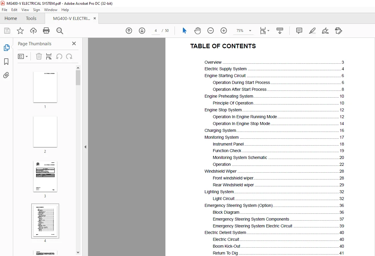
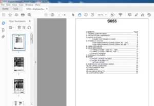
TABLE OF CONTENTS:
Daewoo Doosan MG 400 -V ELECTRICAL SYSTEM manual – PDF DOWNLOAD
Overview ………………………………………………………………………………………….. 3
Electric Supply System ………………………………………………………………………. 4
Engine Starting Circuit ……………………………………………………………………….. 6
Operation During Start Process…………………………………………………….. 6
Operation After Start Process ……………………………………………………….. 8
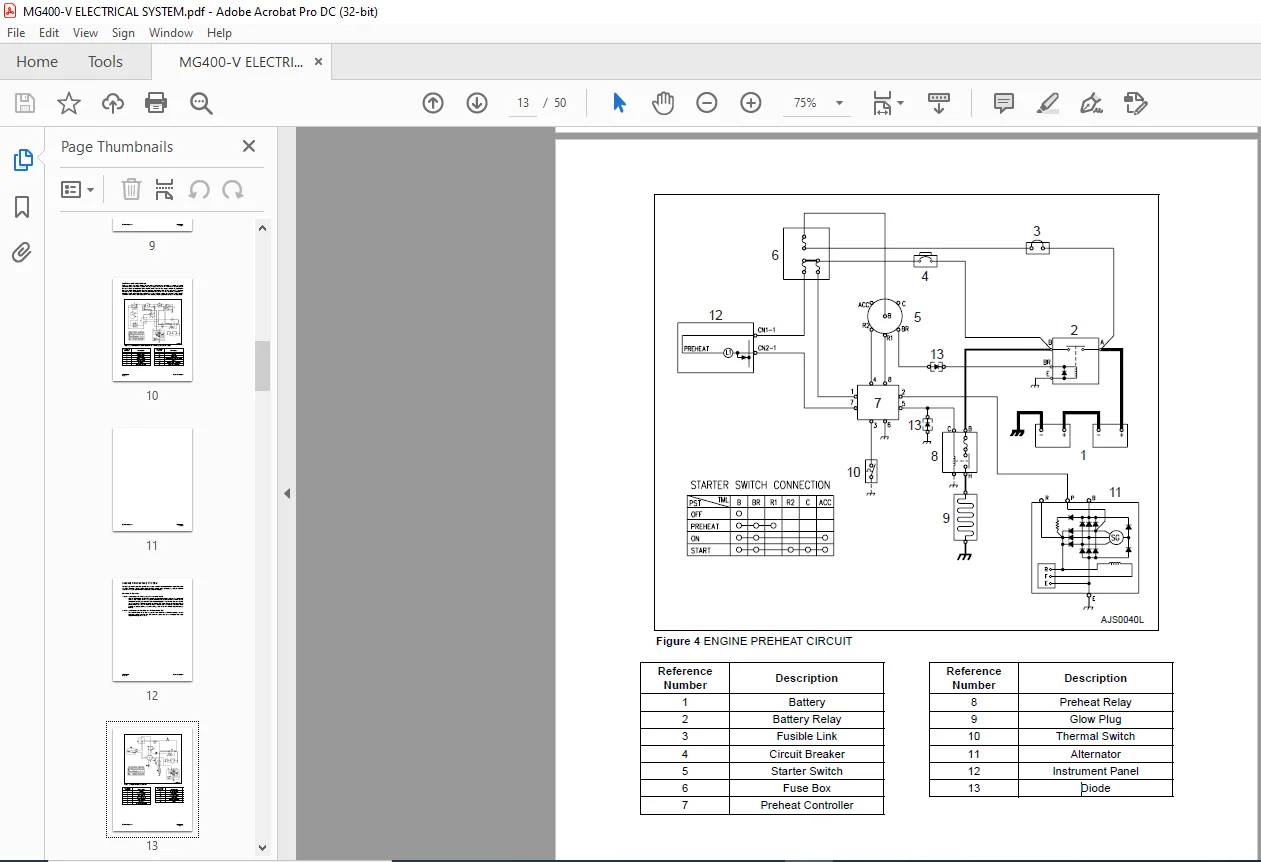
Engine Preheating System………………………………………………………………… 10
Principle Of Operation………………………………………………………………… 10
Engine Stop System…………………………………………………………………………. 12
Operation In Engine Running Mode……………………………………………… 12
Operation In Engine Stop Mode…………………………………………………… 14
Charging System……………………………………………………………………………… 16
Monitoring System …………………………………………………………………………… 17
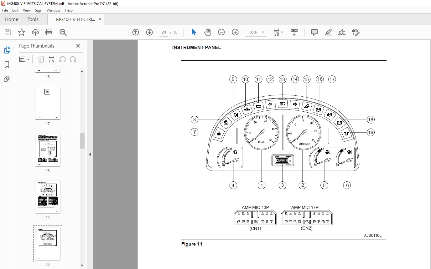
Instrument Panel ……………………………………………………………………….. 18
Function Check …………………………………………………………………………. 19
Monitoring System Schematic …………………………………………………….. 20
Operation …………………………………………………………………………………. 22
Windshield Wiper …………………………………………………………………………….. 28
Front windshield wiper………………………………………………………………… 28
Rear Windshield wiper ……………………………………………………………….. 29
Lighting System……………………………………………………………………………….. 32
Light Circuit ………………………………………………………………………………. 32
Emergency Steering System (Option)…………………………………………………. 36
Block Diagram…………………………………………………………………………… 36
Emergency Steering System Components ……………………………………. 37
Emergency Steering System Electric Circuit …………………………………. 39
Electric Detent System……………………………………………………………………… 40
Electric Circuit …………………………………………………………………………… 40
Boom Kick-Out ………………………………………………………………………….. 40
Return To Dig …………………………………………………………………………….
Customer Support: [email protected]
IMAGES PREVIEW OF THE MANUAL:


PLEASE NOTE:
- This is the same manual used by the dealers to diagnose and troubleshoot your vehicle
- You will be directed to the download page as soon as the purchase is completed. The whole payment and downloading process will take anywhere between 2-5 minutes
- Need any other service / repair / parts manual, please feel free to contact [email protected] . We still have 50,000 manuals unlisted
S.M
Ameer –
Fast and efficient business!