
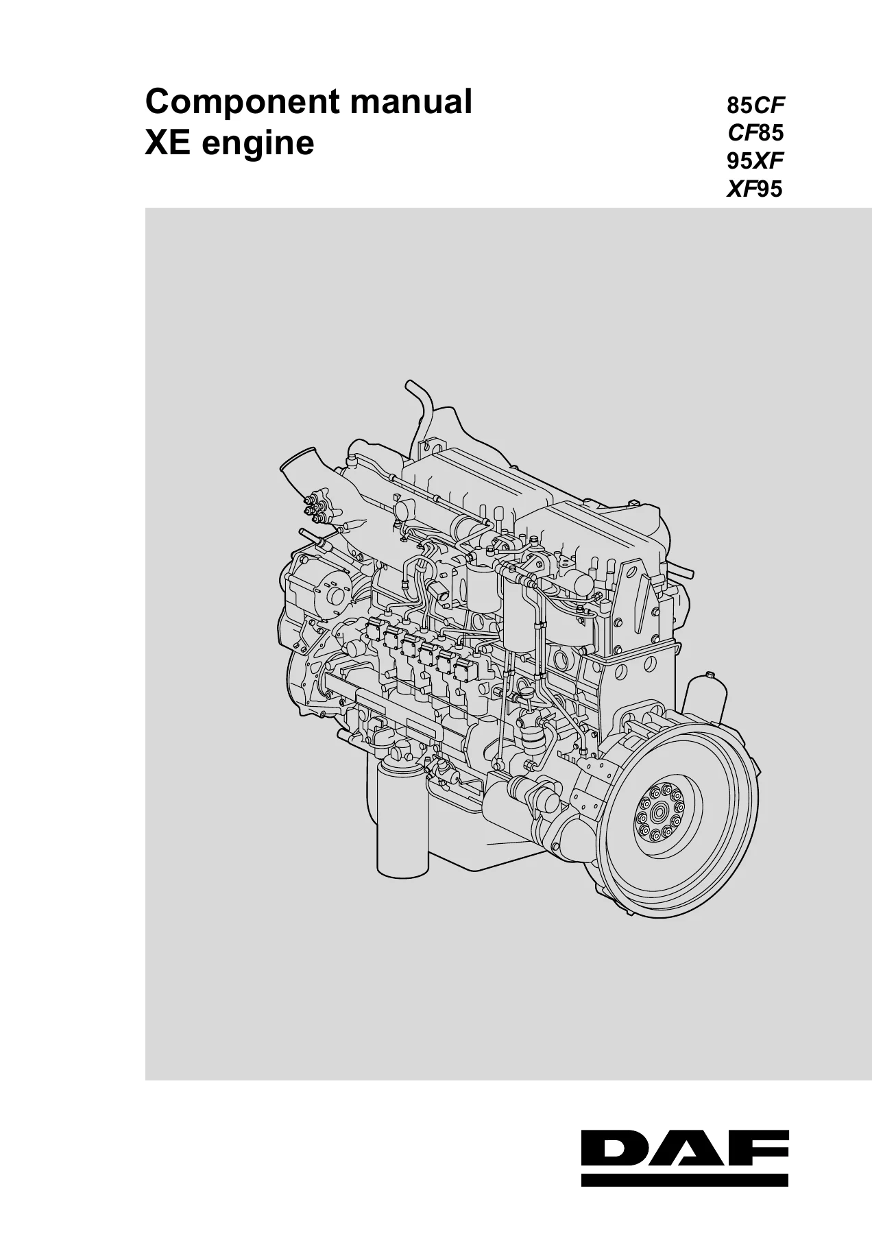
DAF 85CF CF85 95XF XF95 XE Engine Component Manual DW13243204 – Workshop Repair PDF
Original price was: $52.95.$34.95Current price is: $34.95.
Complete DAF XE engine component workshop manual covering XE 250 C, XE 280 C, XE 315 C, XE 355 C, XE 390 C and C1 variants. Includes technical data, tightening torques, inspection and adjustment procedures, removal and installation, disassembly and assembly for all major engine systems.
Description
DAF XE Engine Component Manual – DW13243204
This DAF 85CF CF85 95XF XF95 XE Engine Component Manual (document number DW13243204) is the complete workshop reference for the XE series of diesel engines fitted to DAF heavy trucks. It covers XE 250 C, XE 280 C, XE 315 C/C2, XE 355 C, XE 390 C and their C1-generation counterparts – XE 250 C1, XE 280 C1/C3, XE 315 C1/C3, XE 355 C1 and XE 390 C1. Every major engine system is documented with technical data, tightening torques, step-by-step removal and installation procedures, inspection and adjustment values, and disassembly and assembly instructions.
File Details
- Manual Type: Component Manual / Workshop Manual
- Brand: DAF
- Vehicle Models: 85CF, CF85, 95XF, XF95
- Engine Models: XE 250 C, XE 280 C, XE 315 C/C2, XE 355 C, XE 390 C, XE 250 C1, XE 280 C1/C3, XE 315 C1/C3, XE 355 C1, XE 390 C1
- Language: English
- Page Count: 298
- File Format: PDF
- Document Number: DW13243204
- Publication Code: 200551
- Publisher: DAF Trucks N.V., Eindhoven, The Netherlands
Chapters Covered
- 1. Safety Instructions
- 2. General
- 3. Threaded Connections
- 4. Construction Parts
- 5. Fuel System
- 6. Cooling System
- 7. Timing Gear
- 8. Flywheel and Flywheel Housing
- 9. Cylinder Head
- 10. Lubrication System
- 11. Cylinder Block and Driving Gear
- Fault-Finding Tables (Construction Parts, Engine Brake, Fuel System, Cooling System, Timing Gear, Flywheel and Flywheel Housing, Cylinder Head, Lubrication System, Cylinder Block and Driving Gear)
General and Engine Data
The General chapter opens with the engine type designation system for the XE … C and XE … C1 families, explaining how to identify each variant from the type plate. It provides full engine data: six cylinders, four valves per cylinder, 130 x 158 mm bore and stroke, 12.6 litre total cubic capacity, compression ratio of 16.0:1 for the C engines and 17.4:1 for the C1 engines, direct fuel injection with an injection sequence of 1-5-3-6-2-4, turbocharger intercooling, UPEC engine management and fluid cooling. Engine weight is approximately 1,080 kg. Power and torque figures are listed for every engine type, from the XE 250 C at 250 kW (340 hp) up to the XE 390 C at 390 kW (530 hp).
Threaded Connections and Construction Parts
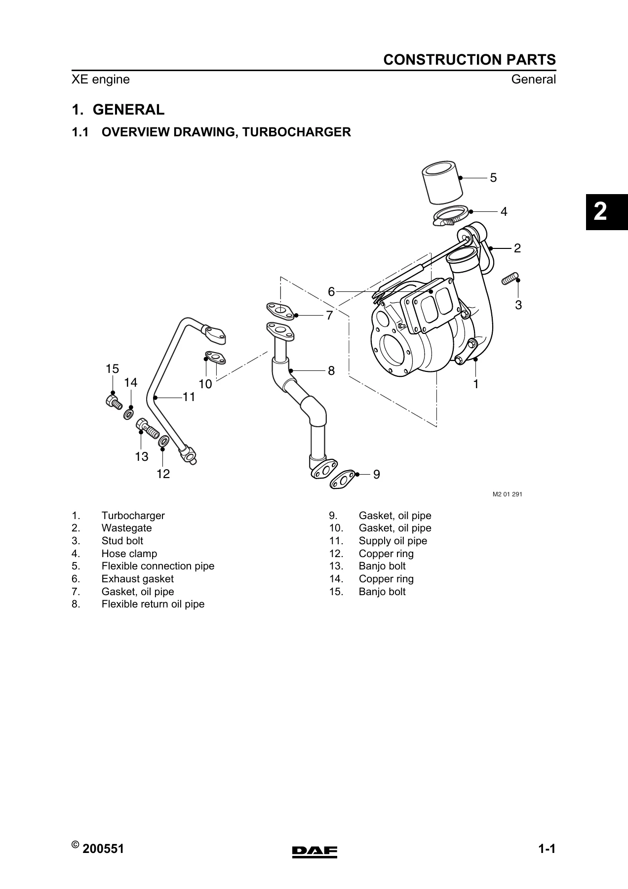
Chapter 3 covers dipped threaded connections, locking compounds and sealants, and includes the complete table of standard tightening torques for dipped threaded connections across property classes 8.8, 12.9 and clamping flange bolts. It also provides the standard tightening torques for DAF flange bolts and nuts (strength class 10.9/10) with angular displacement values based on bolt stem length, plus guidance on re-using bolts and nuts. The Construction Parts chapter supplies V-belt tension values for new and run-in belts, turbocharger type designation explanations for both Garrett and KKK units, wastegate adjustment pressures, exhaust brake calibration openings, and a full set of tightening torques for the starter motor, alternator, air compressor, exhaust manifold, turbocharger, intercooler piping, inlet manifold, relay grid heater, main fuse, engine hanger brackets and all fan drive configurations (direct, separate and up-speed).
Fuel System
The Fuel System chapter begins with injector specifications for each engine type – number of holes, nozzle number, hole diameter, filter type and opening pressure (300 + 10 bar for all XE … C engines). Pump housing dimensions are listed, including roller tappet bore, camshaft bearing bores, roller tappet diameter and camshaft bearing widths. Tightening torques cover injector pipes, injectors, pump housing, pump units, lift pump, fuel filter and fuel filter housing. The later detailed section provides inspection and adjustment procedures for injector opening pressure, injector operation, fuel lift pump (both Barnes and LUK versions), pump housing camshaft and roller tappets, and pump units. Removal and installation procedures are given for fuel injection pipes, injectors, pump units, pump housing and fuel lift pump, followed by disassembly and assembly of the injector and pump housing, and a cleaning procedure for injectors.
Cooling System, Timing Gear, Flywheel and Flywheel Housing
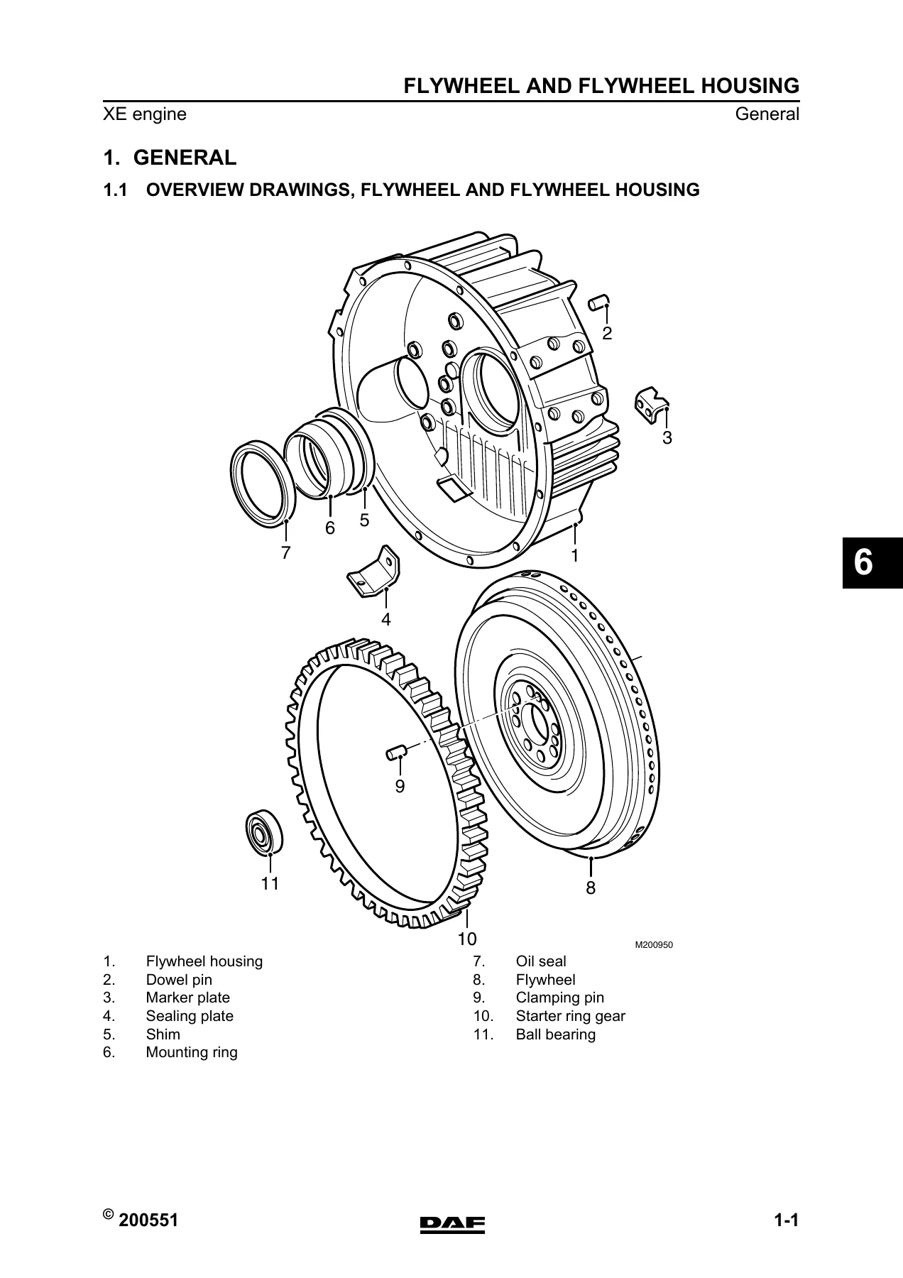
The Cooling System chapter lists thermostat opening temperatures (standard: opens at ±87°C, fully open at ±99°C; with intarder and/or tropical cooling: opens at ±83°C, fully open at ±95°C), thermostat seat locking compound, coolant pump maximum radial play of 0.16–0.20 mm, and tightening torques for the coolant pump, coolant pipe, thermostat housing and coolant hoses. The Timing Gear chapter gives the number of teeth for every gear in the train, gear backlash ranges for each gear pair, and end play values for the crankshaft, camshaft and idler gear, followed by tightening torques for all timing gear components. The Flywheel and Flywheel Housing chapter covers flywheel axial variation (maximum 0.10 mm measured at a radial distance of 210 mm), starter ring gear warm-up temperature (maximum 185°C), and tightening torques for the flywheel housing, flywheel (standard and with engine PTO) and engine mounting at the flywheel end.
Cylinder Head
The Cylinder Head chapter is one of the most detailed in the manual. It provides cylinder head minimum height after refacing (119.5 mm), roughness value, flatness limit and air test pressure. Valve seat dimensions are given for both inlet and exhaust loose seats, including seat angle, internal and external diameters, thickness and minimum thickness after overhaul. Valve guide dimensions, valve stem diameters, valve clearance, valve spring lengths (untensioned and fitted) for inlet, exhaust outer, exhaust inner and single spring configurations, rocker shaft diameter and DEB solenoid valve resistance values are all listed. Cylinder head attachment bolt tightening is specified in four phases: M16 bolts at 50 Nm, then 150 Nm, then 60° angular displacement, then 120° angular displacement; M12 bolts at 110 Nm. Valve gear, DEB and valve sleeve tightening torques complete the chapter.
Lubrication System and Cylinder Block
The Lubrication System chapter covers oil pressure at idle (1 bar warm engine) and at full-load engine speed (3.5–4.5 bar), oil filter types (threaded filter for XE … C, filter element for XE … C1), bypass valve opening pressure (2.5 ± 0.3 bar), oil cooler coolant test pressure (maximum 2.5 bar), and maximum permissible engine oil consumption (0.3% of average fuel consumption). Filling capacities are given for both engine generations: XE … C takes approximately 32 litres total including oil cooler and filter, with a sump capacity of 25 litres at maximum level and 17 litres at minimum level; XE … C1 takes approximately 35 litres total, with 30 litres maximum and 22 litres minimum sump capacity. Tightening torques cover the oil sump, oil pump, strainer, lubricating oil filter, bypass pressure regulator, oil cooler and centrifugal oil filter. The Cylinder Block and Driving Gear chapter provides wear measurement overviews for the cylinder block and crankshaft, cylinder liner dimensions (standard and oversize), crankshaft main and connecting rod journal diameters with undersize steps, axial thrust washer thicknesses, connecting rod dimensions, piston and piston ring specifications, gudgeon pin diameter, roller tappet dimensions, camshaft journal diameter and cam height, and a camshaft wear table based on distance covered. Main bearing cap tightening is specified in three phases: 50 Nm, 150 Nm, 120° angular displacement. Big-end bearing cap tightening varies by production period and engine type, with detailed sequences and angular displacement values.
Fault-Finding Tables
A complete fault-finding section covers symptoms and remedies across all major systems. For construction parts, it addresses reduced power at all engine speeds, reduced power above a certain engine speed, high fuel consumption, reduced maximum engine speed, exhaust brake failure and exhaust brake remaining engaged. For the engine brake, it covers exhaust brake and DEB engagement faults. For the fuel system, it diagnoses engine starts but does not fire, engine stalls and fires again after restarting, poor firing, increased idling speed, diesel knock during acceleration, irregular running, reduced power, white/blue smoke, black smoke, overheating and high fuel consumption. Cooling system faults include engine temperature increase, external coolant leakage and internal coolant leakage. Additional tables cover timing gear noise, excessive engine vibration, cylinder head gasket failure, broken inlet and exhaust valves, cracked and burnt exhaust valve discs, DEB faults, low engine oil pressure, high oil consumption, valve impressions on pistons, cracked and melted piston heads, piston ring and liner wear, connecting rod damage, tappet roller damage, bearing shell wear and camshaft pitting.
Your Complete DAF XE Engine Workshop Reference
This DAF XE engine component manual gives you the exact procedures and specifications needed to service, repair and diagnose the XE 250 C through XE 390 C1 engines fitted to 85CF, CF85, 95XF and XF95 trucks. Whether you are replacing a cylinder head, setting valve clearance, adjusting the DEB, overhauling the fuel system, rebuilding the lubrication system or tracking down a fault code, the manual provides the torque values, clearances, wear limits, tightening sequences and step-by-step instructions that keep the job accurate and the engine reliable. The fault-finding tables alone can save hours of diagnostic guesswork by pointing directly to likely causes and remedies for common symptoms.
IMAGES PREVIEW
Delivered as an instant PDF download, this manual is ready to use on any device – workshop PC, laptop, tablet or smartphone. No shipping, no waiting, no physical book to lose. Print the pages you need for the job at hand or keep the entire 298-page reference on your shop computer for quick access. The DAF 85CF CF85 95XF XF95 XE Engine Component Manual DW13243204 is the practical, professional-grade resource for anyone maintaining or repairing these DAF heavy truck engines.
Reviews
There are no reviews yet.