
DAF XF CF Euro 4 & 5 Electrical Wiring Diagrams Manual – Complete Truck Workshop PDF
Original price was: $59.95.$39.95Current price is: $39.95.
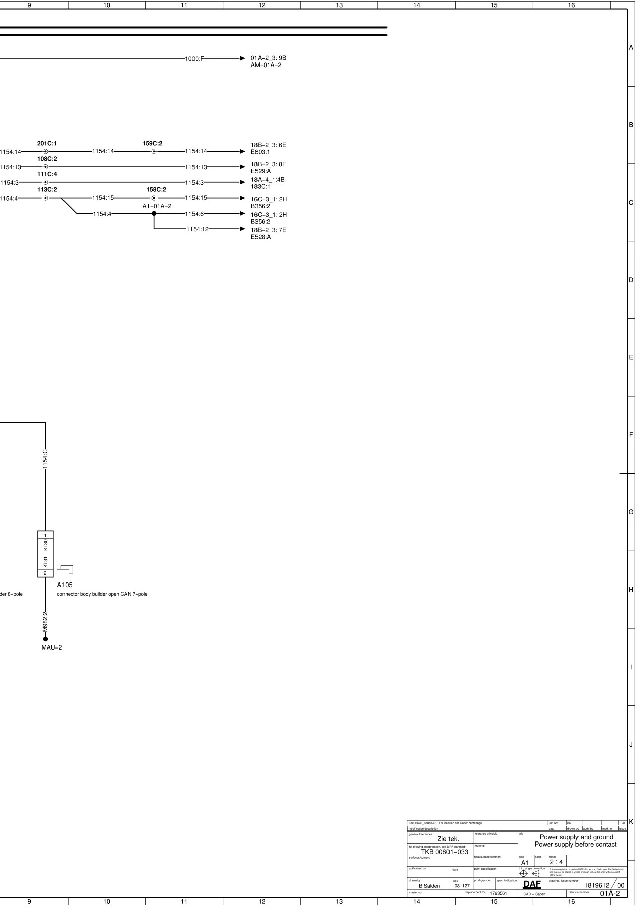
The complete DAF XF CF Euro 4 and 5 electrical wiring diagrams manual – covers V-CAN, I-CAN, D-CAN, BB-CAN, engine DMCI, EBS, ABS-E, ECAS, VIC-2, lighting, climate and every major truck system. 199 pages of factory wiring schematics in one PDF.
Description
DAF XF CF Euro 4 and 5 Electrical Wiring Diagrams Manual
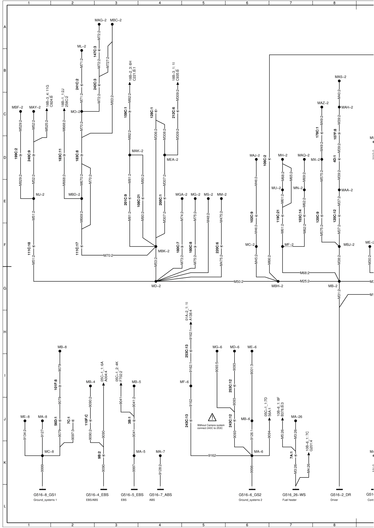
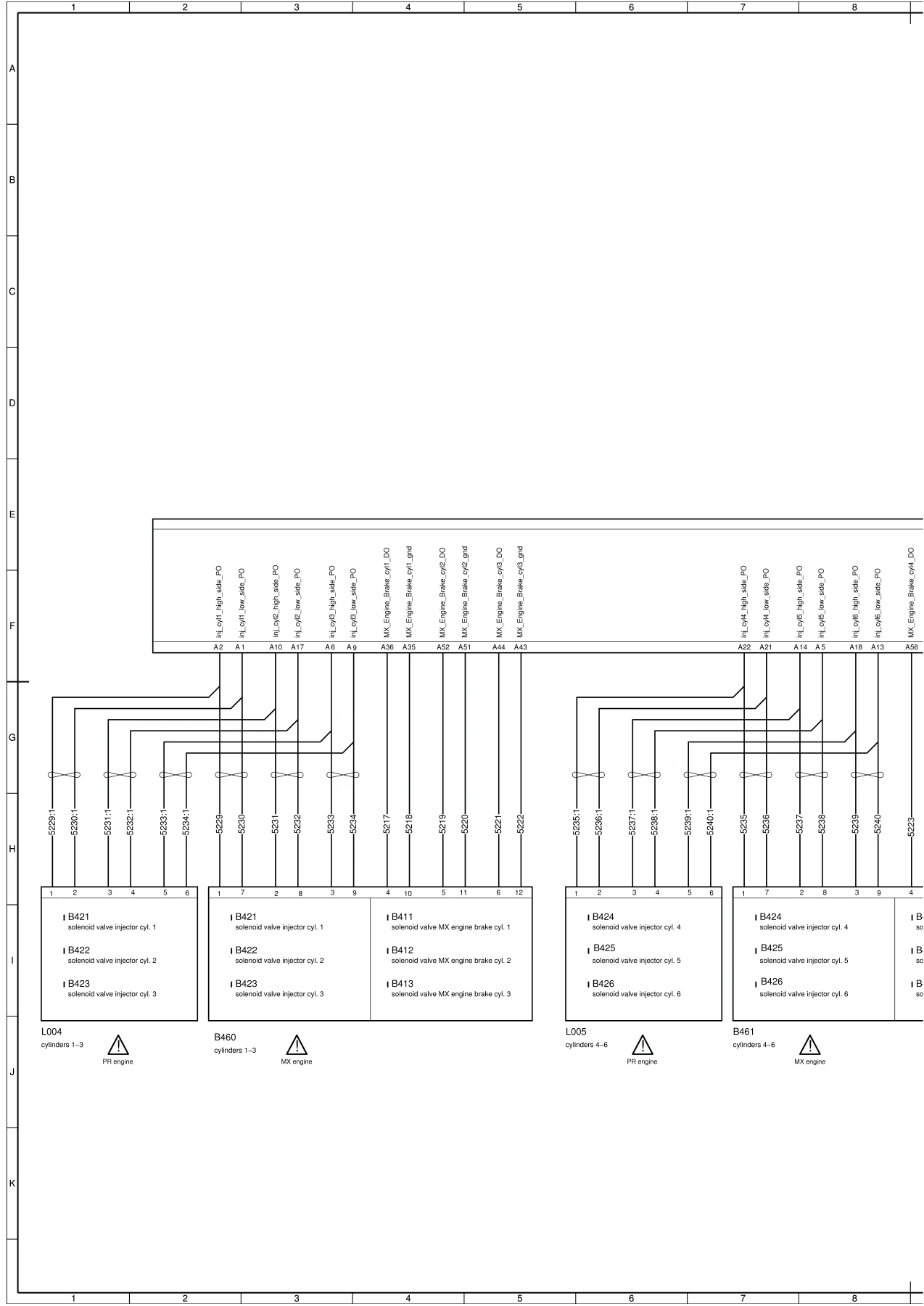
This is the complete electrical wiring diagrams manual for DAF XF and CF trucks built to Euro 4 and Euro 5 emission standards. Across 199 pages, it maps every major electrical system on the vehicle – from battery and ground distribution through to CAN network topology, engine management, braking, transmission, climate control, lighting and body builder interfaces. Every diagram is a proper factory schematic with connector pin numbers, wire colours, component codes and routing, so you can trace a circuit from fuse to ECU to actuator without guessing.
Document number TKB 00801-033 appears throughout the drawing title blocks.
File Details
- Manual type: Electrical Wiring Diagrams
- Brand: DAF
- Models: XF, CF
- Application: Euro 4 and Euro 5
- Language: English
- Page count: 199
- File format: PDF
- Document number: TKB 00801-033
Chapters Covered
- Power Supply and Ground
- Network Topology
- Engine System
- After Treatment System
- Brake System
- Retarder System
- Transmission System
- Tachograph
- Vehicle Control System VIC-2
- Safety System
- CAB Climate System
- Supplementary Vehicle System
- Security System
- Lighting System
- Audio / Vision System
- Communication System
- Additional / Modified Systems
Power Supply and Ground
Battery feed, main switch, dual battery configurations, power generation and both pre- and post-contact supply distribution. Includes fuse holder layouts, ground point locations and the full ground distribution schematic for the chassis and cab. Essential for diagnosing parasitic draws, voltage drops and no-crank conditions.
Network Topology
Complete CAN bus architecture: V-CAN1, V-CAN2, I-CAN, D-CAN, BB-CAN and TT-CAN, plus K-line diagnostics. Shows every ECU connection, terminating resistor locations, twist-pair routing and distribution block pinouts. The backbone for any communication fault diagnosis.
Engine System – DMCI
DMCI engine management wiring: injector solenoids, engine brake solenoids, accelerator pedal sensors, coolant temperature, boost pressure, crankshaft and camshaft sensors, fan clutch control and the engine speed output to the tachograph. Includes ECU pinouts for the D965 DMCI module.
After Treatment System – EAS 2
EAS-2 unit wiring with NOx sensors before and after catalyst, exhaust temperature sensors, AdBlue dosing module, tank level and temperature sensors, and the valve tank heater circuit. Covers both the sensor side and the dosing control side of the SCR system.
Brake System – EBS 2 and ABS-E
EBS-2 and ABS-E wiring schematics including modulator connections, wheel speed sensors, brake pad wear sensors, ASR and retarder interface, and the trailer ABS/EBs connector. Traces every circuit from the ECU to the axle modulators and sensors.
Retarder System – EST 42
EST-42 retarder ECU wiring with coolant temperature sensor, control switches and the interface to the engine and transmission systems. Covers the retarder control connector and the enable/disable logic circuits.
Transmission System – AGC-A and AS Tronic
AGC-A automated gearbox wiring with selector, clutch actuator, range change and splitter solenoids, speed sensors and the AS Tronic steering column gear shift. Includes the neutral/reverse switch and drive mode selector circuits.
Tachograph
Tachograph wiring including sender, sensor and the interface to the vehicle speed signal. Covers the connector pinout and the K-line diagnostic connection.
Vehicle Control System VIC-2
The largest section of the manual – VIC-2 covers lighting control, door locking, wiper/washer, mirror adjustment, window control, mirror heating, interior lighting, work lights, search lights, reverse lights, marker lights, stop lights, fog lights, driving lights and headlamp leveling, turn signals, hazard warning, cab tilt, air suspension control, PTO control, engine running take-over, neutral/reverse position sensing, park brake warning, and much more. Every input and output pin on the VIC-2 ECU is documented with wire numbers and component references.
Safety System
Airbag-2 ECU with seat belt tensioner and airbag squib circuits. Lane Departure Warning Assistant and camera system wiring, including the camera connector pinout and the interface to the VIC-2 and DAF Telematics System.
CAB Climate System
Airtronic air heater, Hydronic water heater, and the combined heater/airco/ATC system. Covers blower motor control, temperature sensors, refrigerant pressure switches, and the auxiliary heater timer and relay circuits.
Supplementary Vehicle System
Auxiliary heater, horn, seat heating, driver seat socket, air dryer, cabin height control, 40 A socket, refrigerator, roof hatch, mirror adjustment, window control, mirror heating, spare wiring, tail preparation and dual fuel tank levelling. A comprehensive collection of body and comfort system schematics.
Security System – ALS
Alarm system ALS wiring with door, bonnet and cargo area switches, radar sensor, interior detection and the alarm siren and indicator outputs. Covers the connector pinout for the D911 alarm ECU.
Lighting System – Exterior
Driving lights and headlamp leveling, stop lights, reverse lights, rotating beacons, auxiliary lights, fog lights and marker lights. Includes the trailer connector pinout for 7-pole and 15-pole sockets, plus work lights and the rear light cluster wiring.
Lighting System – Interior
Step lights, interior lighting, roof hatch lights, search lights and the interior light relay and switch logic. Covers the cab interior light module and the door switch inputs.
Audio / Vision System
Radio wiring with speaker outputs, microphone input, phone interface, aerial connections and the high-end amplifier option. Includes the connector pinout for the radio head unit and the speaker layout for both standard and high-end audio.
Communication System
Telephone interface, FMS (Fleet Management System), Toll Collect and the DAF Telematics System (DTS). Covers the GSM and GPS antenna connections, the telematics ECU pinout and the FMS connector for body builder interface.
Additional / Modified Systems
Customer-specific requirements, PTO (Power Take-Off) systems, body builder module wiring and the connector definitions for body builder interfaces. Essential when integrating specialist equipment onto the chassis.
Why This Wiring Diagrams Manual Matters
Electrical faults on Euro 4 and Euro 5 DAF trucks are rarely simple. With multiple CAN networks, dozens of ECUs and complex power distribution, guessing at wiring is expensive and time-consuming. This manual gives you the exact circuit path for every system – which connector, which pin, which wire colour, which fuse. Whether you are diagnosing a non-starting engine, a CAN communication fault, a lighting failure or a body builder integration issue, the answer is in these pages.
The diagrams are presented in the same format the DAF dealer network uses, with component codes that match the vehicle, so there is no translation layer between the manual and the truck. If you run a workshop, manage a fleet, or work on your own DAF XF or CF, this manual pays for itself the first time you use it.
IMAGES PREVIEW
Instant PDF Delivery
This is a digital PDF manual – no shipping, no waiting for a physical book. After payment you can download it immediately and open it on any device: laptop, tablet or smartphone. Print the pages you need for the workshop and keep the rest on file. The PDF is fully self-contained and works offline, so you can take it anywhere the truck goes.
Reviews
There are no reviews yet.