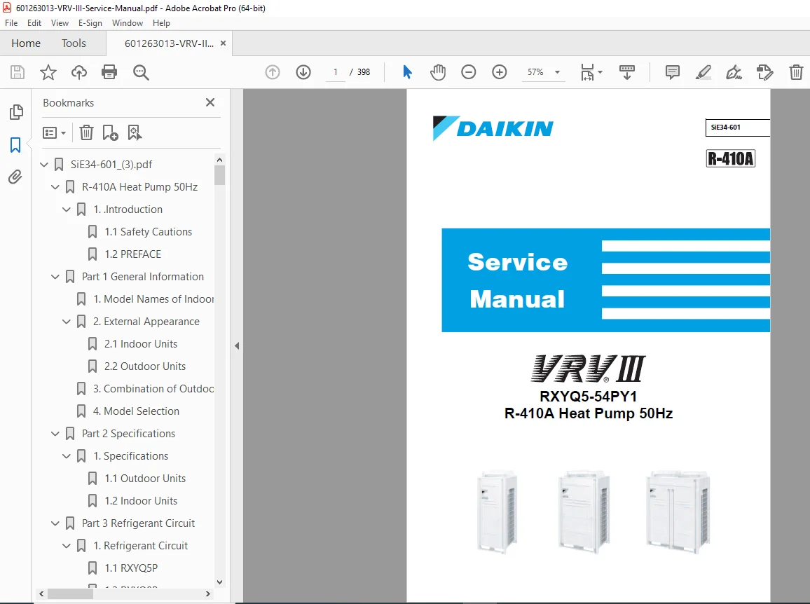
Daikin VRV III Heat Pump Service Manual RXYQ5-54PY1 R-410A System PDF
Original price was: $120.00.$18.95Current price is: $18.95.
Complete factory service manual for Daikin VRV III (Variable Refrigerant Volume) Heat Pump systems. This comprehensive 398-page technical manual covers RXYQ5-54PY1 series outdoor units (5HP to 54HP capacity) with R-410A refrigerant. Includes detailed specifications, refrigerant circuit diagrams, control functions, test operations, troubleshooting procedures, error code diagnostics, wiring schematics, piping diagrams, and R-410A refrigerant handling. Essential reference for HVAC technicians servicing commercial VRV systems.
Description
Daikin VRV III Heat Pump Service Manual RXYQ5-54PY1 R-410A System PDF DOWNLOAD
DESCRIPTION
Daikin VRV III R-410A Heat Pump System – Complete Factory Service Manual
This is the official factory service manual for Daikin’s VRV III (Variable Refrigerant Volume) Heat Pump Series – the industry-leading commercial HVAC system designed for buildings, offices, and large-scale air conditioning applications. Published in June 2006 by Daikin’s After Sales Service Division, this professional-grade technical manual is essential for HVAC technicians, service engineers, and facility maintenance professionals.
With 398 pages of comprehensive technical documentation, this manual provides complete coverage of system architecture, operation principles, servicing procedures, troubleshooting methodologies, and maintenance protocols for VRV III heat pump systems.
Manual Reference: SiE34-601
System Type: R-410A Heat Pump 50Hz
Outdoor Units Covered: RXYQ5-54PY1 Series
🏢 ABOUT DAIKIN VRV III SYSTEMS
VRV (Variable Refrigerant Volume) technology is Daikin’s flagship commercial HVAC solution that allows multiple indoor units of different types and capacities to be connected to a single outdoor unit or combination of outdoor units. The VRV III series offers:
Key System Capabilities:
- Capacity Range: 5HP to 54HP outdoor units
- Refrigerant: R-410A (environmentally improved)
- Frequency: 50Hz power systems
- Operation Modes: Cooling, Heating, Auto changeover
- Multiple Indoor Unit Connections: Flexibility for mixed indoor unit types
- Advanced Inverter Control: Energy-efficient variable-speed compressors
- Heat Recovery Options: Simultaneous heating and cooling capability
Outdoor Unit Models Covered:
- RXYQ5P, RXYQ8P, RXYQ10P, RXYQ12P
- RXYQ14P, RXYQ16P, RXYQ18P
- RXYQ20P through RXYQ54P (various capacities)
- Normal Series and High COP Energy Saving Series
Compatible Indoor Unit Types:
- Ceiling cassette units
- Ceiling concealed duct units
- Wall-mounted units
- Floor-standing units
- Outdoor air processing units (FXMQ125-250MFV1)
📋 COMPREHENSIVE MANUAL CONTENTS
INTRODUCTION (Pages vi-x)
- Safety Cautions – Critical Safety Information
- Warning and Caution Classifications
- Death and serious injury prevention
- Equipment damage prevention
- Proper repair procedures
- Warning and Caution Classifications
- Cautions in Repair Work
- Electrical Safety
- Power disconnection procedures
- Working on energized equipment
- Step-up capacitor discharge requirements
- Proper grounding requirements
- Refrigerant Gas Safety
- Frostbite prevention
- Toxic gas generation warnings
- Leak detection and ventilation
- Pressure release procedures
- Mechanical Safety
- High-speed fan rotation hazards
- Hot surface burn prevention
- Heavy equipment handling
- Electrical Safety
- Cautions Regarding Products After Repair
- Installation Requirements
- Structural strength verification
- Proper mounting and securing
- Electrical circuit requirements
- R-410A Specific Requirements
- No air or gas mixing warnings
- High-pressure safety considerations
- Leak repair before refrigerant charging
- Installation Requirements
- Inspection After Repair
- Power cable and connection verification
- Grounding resistance measurement (≥1 MΩ)
- Drainage system testing
- Insulation resistance verification
- Icon Usage and Conventions
- Note, Caution, Warning symbols
- Reference indicators
- Safety pictograms
- Preface
- VRV III system introduction
- Manual scope and purpose
- Service manual usage guidelines
PART 1 – GENERAL INFORMATION (Pages 1-10)
- Model Names of Indoor/Outdoor Units
- Complete model designation system
- Normal Series vs High COP Series identification
- RoHS Directive compliant models
- Connection unit series overview
- External Appearance
- Indoor Units
- Various indoor unit type illustrations
- Dimensions and mounting details
- Access panel locations
- Outdoor Units
- RXYQ5P through RXYQ54P external views
- Service panel access points
- Connection port locations
- Component identification
- Indoor Units
- Combination of Outdoor Units
- Multiple outdoor unit connection guidelines
- Outdoor Unit Multi Connection requirements
- System capacity combinations
- Piping and wiring connections for combined systems
- Model Selection
- VRV III Heat Pump Series overview
- Normal Series specifications
- High COP Energy Saving Series specifications
- Indoor/outdoor unit compatibility matrix
PART 2 – SPECIFICATIONS (Pages 11-58)
- Outdoor Unit Specifications (Comprehensive)
- RXYQ5P through RXYQ54P Models
- Cooling capacity (kW)
- Heating capacity (kW)
- Power consumption
- EER (Energy Efficiency Ratio)
- COP (Coefficient of Performance)
- Compressor specifications
- Inverter compressor details
- Standard compressor details
- Refrigerant charge amount (kg)
- Oil charge specifications
- Fan specifications
- Number of fans
- Motor output
- Air flow rate (m³/min)
- Noise levels (dB[A])
- Dimensions (H × W × D)
- Weight (kg)
- Piping connections
- Liquid pipe diameter
- Gas pipe diameter
- Maximum piping length
- Maximum height difference
- Operating range
- Cooling operation temperature range
- Heating operation temperature range
- Power supply requirements
- Voltage and frequency
- Phase configuration
- Maximum current draw
- RXYQ5P through RXYQ54P Models
- Indoor Unit Specifications (Complete Range)
- Ceiling cassette models
- Ceiling concealed duct models
- Wall-mounted models
- Floor-standing models
- Each model detailed with:
- Cooling/heating capacities
- Air flow rates
- Noise levels
- Dimensions and weights
- Power consumption
- External static pressure
- Piping connection sizes
PART 3 – REFRIGERANT CIRCUIT (Pages 59-90)
- Refrigerant Circuit Diagrams
- RXYQ5P Circuit
- Injection control system (unique to 5P)
- Subcooling heat exchanger
- RXYQ8P Circuit
- RXYQ10P, 12P Circuits
- RXYQ14P, 16P, 18P Circuits
- Outdoor Air Processing Unit Circuits (FXMQ125-250MFV1)
- RXYQ5P Circuit
- Functional Parts Layout
- Component location diagrams for each outdoor unit model
- Key Components:
- Compressors (Inverter and STD)
- Heat exchangers
- Electronic expansion valves
- Solenoid valves
- Check valves
- Strainers
- Service ports
- Pressure switches and sensors
- Temperature sensors (thermistors)
- Oil separators
- Accumulators
- Receivers
- Refrigerant Flow for Each Operation Mode
- Cooling Operation Flow
- Heating Operation Flow
- Defrost Operation Flow
- Oil Return Operation Flow
- Pump Down Operation Flow
- Detailed flow paths with valve positions
- Color-coded refrigerant state indicators
PART 4 – FUNCTION (Pages 91-142)
- Function General
- Symbol legend and abbreviations
- Operation mode descriptions
- Basic Control Functions
Normal Operation Control
- Capacity control logic
- Indoor/outdoor unit coordination
- Temperature control methodology
Compressor PI Control
- Inverter compressor frequency control
- Target evaporating temperature calculation
- Target condensing temperature calculation
- PI control algorithm explanation
- Frequency adjustment based on load
- Startup frequency control
- Operating frequency limits
Electronic Expansion Valve PI Control
- Superheat control
- Subcooling control
- Opening degree calculation
- Response to load changes
Step Control of Outdoor Unit Fans
- Multi-stage fan speed control
- Load-based fan operation
- Energy optimization
Outdoor Unit Fan Control in Cooling Operation
- Condensing pressure control
- Ambient temperature compensation
- Special Control Functions
Startup Control
- Pre-operation checks
- Compressor startup sequence
- Gradual capacity increase
Large Capacity Startup Control (Heating)
- High-power heating startup procedure
- Preventing liquid compression
Oil Return Operation
- Periodic oil return sequence
- High-frequency compressor operation
- Oil collection from indoor units
Defrosting Operation
- Frost detection logic
- Reverse cycle defrost procedure
- Defrost termination conditions
- Hot gas bypass defrost (select models)
Pump-Down Residual Operation
- Refrigerant recovery to outdoor unit
- Service mode pump-down
Standby Operation
- Low-load standby mode
- Energy conservation
Stopping Operation
- Controlled shutdown sequence
- Valve positioning for next startup
- Protection Control Functions
High Pressure Protection Control
- High-pressure switch monitoring
- High-pressure sensor monitoring
- Capacity reduction procedures
- System shutdown thresholds
Low Pressure Protection Control
- Low-pressure sensor monitoring
- Refrigerant shortage detection
- Leak prevention shutdown
Discharge Pipe Protection Control
- Overheating prevention
- Compressor protection
- Temperature monitoring
Inverter Protection Control
- Overcurrent protection
- Over-voltage protection
- Radiating fin temperature protection
- IPM (Intelligent Power Module) protection
STD Compressor Overload Protection
- Thermal overload relay
- Current monitoring
Injection Control (RXYQ5P only)
- Economizer circuit control
- Enhanced efficiency operation
- Other Control Functions
Outdoor Unit Rotation
- Load balancing between multiple outdoor units
- Equalized wear and tear
Emergency Operation
- Continued operation with failed components
- Reduced capacity operation modes
- Manual override procedures
Demand Operation
- Power consumption limiting
- Demand response capability
- Load shedding control
Heating Operation Prohibition
- Summer-only operation setting
- Energy management feature
- Indoor Unit Control Outline
Drain Pump Control
- Condensate pump operation
- Float switch monitoring
- Overflow prevention
Louver Control for Preventing Ceiling Dirt
- Air direction optimization
- Stain prevention logic
Thermostat Sensor in Remote Control
- Remote sensor temperature control
- Room temperature monitoring
Thermostat Control – Normal Operation
- ON/OFF cycling based on setpoint
- Hysteresis settings
Thermostat Control – Dry Operation
- Humidity control mode
- Temperature and capacity modulation
Electronic Expansion Valve Control (Indoor)
- Superheat adjustment
- Capacity matching
Hot Start Control
- Preventing cold air blow in heating
- Fan delay until discharge temperature rises
Freeze Prevention
- Low temperature protection
- Compressor shutdown to prevent icing
Heater Control
- Auxiliary electric heater operation
- Supplemental heating in low ambient
Swing Flap Operations List
- Auto swing patterns
- Fixed position modes
Outdoor Air Processing Unit Unique Control
- Fresh air introduction control
- Enthalpy control
- CO2 sensor integration
PART 5 – TEST OPERATION (Pages 143-198)
- Test Operation Procedures
- Installation Process Flowchart
- Pre-installation checks
- Piping installation verification
- Electrical wiring verification
- Evacuation and refrigerant charging
- Test run preparation
- Installation Process Flowchart
- Procedure and Outline
- Vacuum Drying Procedure
- Refrigerant Charging Procedure
- Liquid charging method
- Gas charging considerations
- Proper charge verification
- Test Run Execution
- Forced cooling operation
- Forced heating operation
- All indoor units simultaneous operation
- Individual indoor unit testing
- Performance Verification
- Temperature measurements
- Pressure readings
- Current draw verification
- Air flow testing
- Operation When Power is Turned On
- Initial power-up sequence
- Self-diagnostic checks
- System initialization
- Outdoor Unit PC Board Layout
- Main control board location
- Inverter board location
- Terminal block identification
- LED indicator positions
- DIP switch settings
- Field Setting
Field Setting from Remote Control
- Entering service mode
- Available field settings list:
- Refrigerant pipe length correction
- Indoor unit capacity setting
- Address setting
- Oil return operation interval
- Defrost operation settings
- Fan speed settings
- Temperature compensation
- Night quiet operation
- And many more…
- Setting procedures with screen navigation
- Confirmation and saving settings
Field Setting from Outdoor Unit
- DIP switch configurations
- PC board parameter settings
- Service mode activation
- Available outdoor unit settings:
- System configuration
- Pipe length settings
- Height difference settings
- Combined system settings
- Protection settings
- Parameter modification procedures
PART 6 – TROUBLESHOOTING (Pages 199-314)
- Symptom-Based Troubleshooting
- Unit does not operate
- Poor cooling/heating performance
- Unusual noise
- Water leakage
- Abnormal odor
- Systematic diagnostic approach
- Troubleshooting by Remote Control
The INSPECTION / TEST Button
- Accessing diagnostic mode
- Button operation sequences
Self-Diagnosis by Wired Remote Control
- Error code display
- System status monitoring
- Test operation activation
Self-Diagnosis by Infrared Remote Control
- Error code retrieval
- Display interpretation
Remote Control Service Mode
- Advanced diagnostic functions
- Real-time monitoring
- Component testing
Remote Control Self-Diagnosis Function
- Communication verification
- Sensor reading display
- Operating parameter display
- Comprehensive Error Code Troubleshooting
Indoor Unit Error Codes (A-Series):
“A0” – External Protection Device Error
- Cause analysis
- Diagnostic flowchart
- Repair procedures
“A1” – PC Board Defect
- Board failure diagnosis
- Replacement procedures
- Communication verification
“A3” – Drain Level Control Malfunction
- Float switch testing
- Pump operation check
- Drainage system inspection
“A6” – Fan Motor Lock/Overload
- Motor resistance testing
- Bearing inspection
- Control circuit verification
“A7” – Swing Flap Motor Malfunction
- Motor operation test
- Position sensor verification
- Mechanical obstruction check
“A9” – Electronic Expansion Valve Malfunction
- Coil resistance testing
- Valve movement verification
- Replacement procedure
“AF” – Drain Level Above Limit
- Emergency shutdown response
- Drain blockage clearing
- Pump repair/replacement
“AJ” – Capacity Determination Device Malfunction
“C4” – Heat Exchanger Thermistor Malfunction
- Resistance measurement procedure
- Wiring verification
- Sensor replacement
“C5” – Gas Pipe Thermistor Malfunction
“C9” – Suction Air Thermistor Malfunction
“CJ” – Remote Control Thermostat Sensor Malfunction
Outdoor Unit Error Codes (E-Series, F-Series, H-Series, J-Series, L-Series, P-Series):
“E1” – PC Board Defect
- Main board diagnosis
- Replacement and configuration
“E3” – High Pressure Switch Actuation
- Pressure measurement
- Cause determination (overcharge, poor ventilation, fan failure)
- Correction procedures
“E4” – Low Pressure Sensor Actuation
- Refrigerant shortage diagnosis
- Leak detection
- Expansion valve inspection
“E5” – Inverter Compressor Motor Lock
- Mechanical seizure check
- Electrical fault diagnosis
- Compressor replacement
“E6” – STD Compressor Motor Overcurrent/Lock
“E7” – Outdoor Unit Fan Motor Malfunction
“E9” – Electronic Expansion Valve Malfunction
“F3” – Abnormal Discharge Pipe Temperature
- Overheating causes
- Refrigerant charge verification
- Compressor health assessment
“F6” – Refrigerant Overcharged
- Proper charge verification
- Recovery procedure
- Recharging to specification
“H7” – Abnormal Outdoor Fan Motor Signal
“H9” – Outdoor Air Thermistor Malfunction
“J2” – Current Sensor Malfunction
“J3” – Discharge Pipe Thermistor Malfunction
“J5” – Suction Pipe Thermistor Malfunction
“J6” – Heat Exchanger Thermistor Malfunction
“J7” – Liquid Pipe Thermistor Malfunction
“J9” – Subcooling Heat Exchanger Thermistor Malfunction
“JA” – High Pressure Sensor Malfunction
“JC” – Low Pressure Sensor Malfunction
“L4” – Inverter Radiating Fin Temperature Rise
“L5” – Inverter Compressor Abnormal
- IPM protection
- Overcurrent
- Position sensor error
“L8” – Inverter Current Abnormal
“L9” – Inverter Startup Error
“LC” – Inverter-Control Board Communication Malfunction
“P1” – Inverter Over-Ripple Protection
“P4” – Inverter Radiating Fin Temperature Sensor Malfunction
“PJ” – Field Setting Error / Board Combination Error
Communication and System Error Codes (U-Series):
“U0” – Refrigerant Shortage / EEV Failure
“U1” – Reverse Phase / Open Phase
“U2” – Power Supply Insufficient / Instantaneous Failure
“U3” – Check Operation Not Executed
“U4” – Indoor Unit Communication Malfunction
“U5” – Remote Control-Indoor Unit Communication Malfunction
“U7” – Outdoor Unit Communication Malfunction
“U8” – Main-Sub Remote Control Communication Malfunction
“U9” – Indoor-Outdoor Unit Communication Malfunction
“UA” – Improper Combination of Units
“UC” – Centralized Controller Address Duplication
“UE” – Centralized Controller Communication Malfunction
“UF” – System Not Set
“UH” – System/Refrigerant Address Undefined
- Centralized Control Error Codes (M-Series)
“M1” – PC Board Defect
“M8” – Optional Controller Communication Malfunction
“MA” – Improper Combination of Optional Controllers
“MC” – Address Duplication / Improper Setting
- Unified ON/OFF Controller Troubleshooting
- Operation lamp blinking patterns
- Centralized control display issues
- Diagnostic procedures
PART 7 – APPENDIX (Pages 315-370)
- Piping Diagrams
Outdoor Unit Piping
- Complete refrigerant piping schematics
- All models RXYQ5P through RXYQ54P
- Pipe sizing and connections
- Service port locations
- Valve arrangements
Indoor Unit Piping
- Various indoor unit type piping
- Connection details
- Drain piping
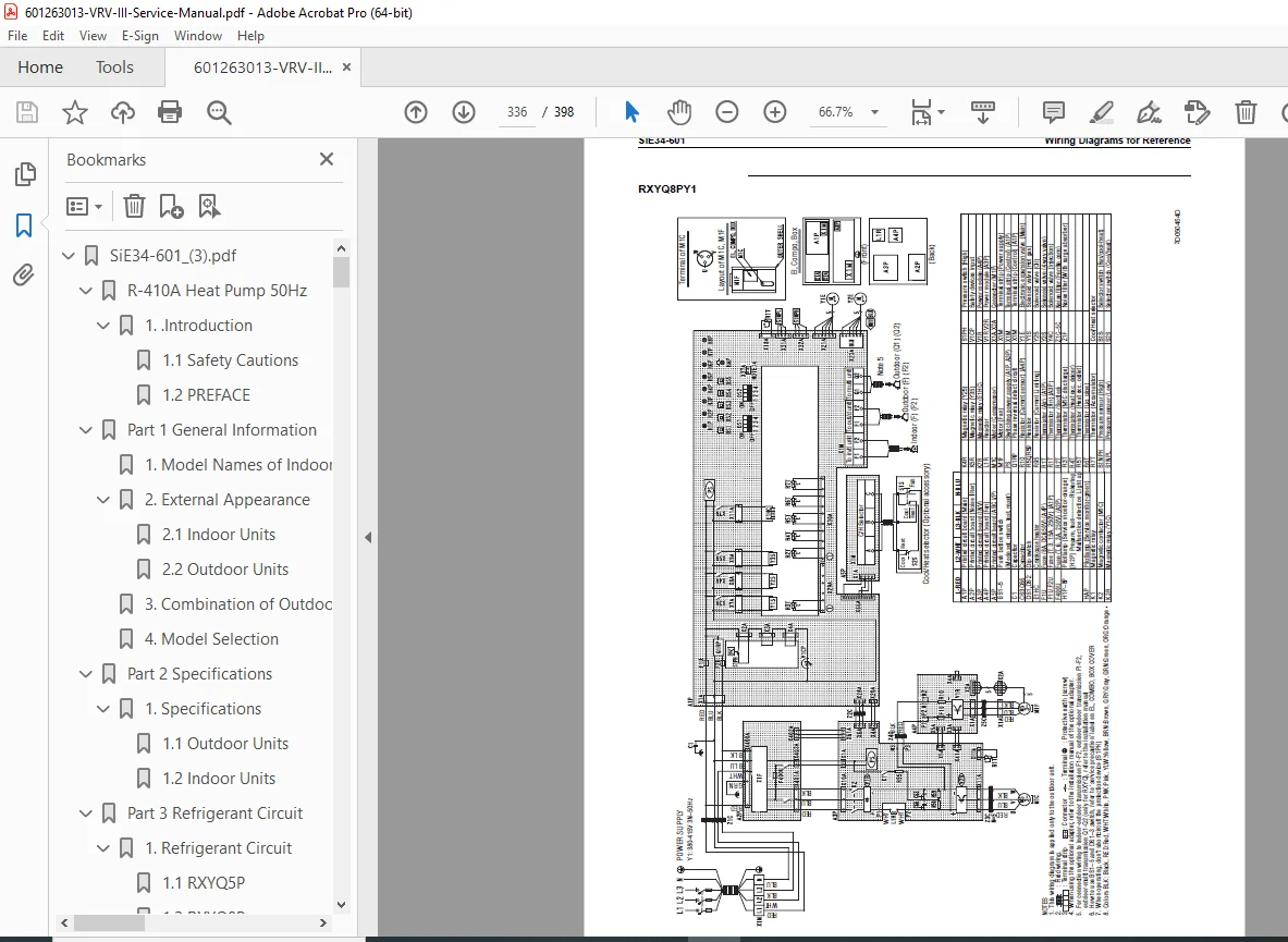
- Wiring Diagrams for Reference
Outdoor Unit Wiring
- Complete electrical schematics
- Power supply wiring
- Control wiring
- Communication wiring
- Terminal block diagrams
- Color-coded wire identification
Field Wiring
- Indoor-outdoor connections
- Remote control wiring
- Power wiring requirements
- Communication bus wiring
- Grounding requirements
Indoor Unit Wiring
- All indoor unit types
- Internal wiring diagrams
- Terminal connections
- Option wiring
- List of Electrical and Functional Parts
Outdoor Unit Parts
- Part numbers
- Component descriptions
- Specifications
- Replacement procedures
Indoor Unit Parts
- Complete parts inventory
- Model-specific components
- Ordering information
- Option List
Controllers
- Wired remote controls
- Wireless remote controls
- Centralized controllers
- Unified ON/OFF controllers
- Schedule timers
- Web controllers
Outdoor Unit Options
- Multi connection kits
- Sound insulation kits
- Winter operation kits
- High-altitude kits
- Piping Installation Points
- Correct piping practices
- Pipe support and insulation
- Refrigerant line sizing
- Oil return considerations
- Trap requirements
- Examples of Wrong Piping Patterns
- Common installation mistakes
- Consequences of improper piping
- Corrective actions
- Connection Examples (R-410A Type)
- System configuration examples
- Multi-outdoor unit connections
- Mixed indoor unit installations
- Piping layouts for various building types
- Thermistor Resistance/Temperature Characteristics
- Temperature vs resistance tables
- All sensor types
- Testing and verification data
- Pressure Sensor Characteristics
- Pressure vs voltage output
- Calibration data
- Testing procedures
- Method of Checking Inverter Power Transistors and Diode Modules
- Multimeter testing procedures
- Component identification
- Good vs failed component readings
- Safety precautions
PART 8 – PRECAUTIONS FOR NEW REFRIGERANT (R-410A) (Pages 371-398)
- R-410A Refrigerant Outline
- Properties of R-410A
- Higher operating pressures vs R-22
- Non-azeotropic mixture characteristics
- Environmental benefits (zero ODP)
- GWP considerations
- Pressure Comparison
- R-410A vs R-22 pressure charts
- High-side pressure differences
- Low-side pressure differences
- Safety implications
- Material Compatibility
- Compatible oils (POE – Polyolester)
- Incompatible materials
- Seal and gasket requirements
- Copper tubing specifications
- Properties of R-410A
- Refrigerant Cylinders
- Color Coding
- Pink cylinder identification
- Preventing mixing with R-22
- Cylinder Valve Types
- Different thread specifications
- Preventing cross-contamination
- Charging Requirements
- CRITICAL: Liquid charging only
- Preventing composition change
- Proper cylinder positioning
- Color Coding
- Service Tools
- R-410A Specific Requirements
- Dedicated manifold gauges
- Higher pressure rating required
- Different port connections
- Dedicated recovery machines
- Oil-less or POE oil compatible
- Dedicated vacuum pumps
- Two-stage recommended
- Deep vacuum capability
- Dedicated charging equipment
- Electronic scales
- Charging hoses
- Dedicated manifold gauges
- Tool Specifications
- Pressure gauge ranges
- Hose pressure ratings
- Recovery machine capacity
- Vacuum pump specifications
- Contamination Prevention
- Never mix R-410A and R-22 tools
- Oil compatibility issues
- System cleaning requirements
- Safety Equipment
- Protective gloves
- Safety glasses
- Ventilation requirements
- R-410A Specific Requirements
- Handling Precautions
- High-pressure safety warnings
- Frostbite prevention
- Proper leak detection methods
- Recovery and recycling requirements
- Environmental regulations compliance
📚 ADDITIONAL SECTIONS
- Index – Comprehensive alphabetical reference
- Drawings & Flow Charts – Quick visual reference guide
🔧 KEY TECHNICAL FEATURES
✅ Complete VRV III Coverage – All outdoor unit models 5HP to 54HP
✅ R-410A Refrigerant – Modern environmentally-improved refrigerant system
✅ Inverter Technology – Variable-speed compressor control and optimization
✅ Error Code Database – 50+ error codes with diagnostic flowcharts
✅ Refrigerant Circuit Diagrams – Detailed flow paths for all operation modes
✅ Control System Explanation – PI control, protection, and special functions
✅ Field Setting Procedures – Complete configuration and setup guidance
✅ Test Operation Guide – Installation verification and commissioning
✅ Wiring Schematics – Complete electrical diagrams for all components
✅ Piping Diagrams – Proper refrigerant line installation
✅ Parts Lists – Complete component identification and part numbers
📄 FILE DETAILS
| Specification | Details |
|---|---|
| Manual Reference | SiE34-601 |
| Manual Name | VRV III R-410A Heat Pump Service Manual |
| System Type | Variable Refrigerant Volume (VRV) Heat Pump |
| Models Covered | RXYQ5-54PY1 Series (5HP to 54HP outdoor units) |
| Refrigerant | R-410A (HFC refrigerant) |
| Frequency | 50Hz |
| Publication Date | June 2006 |
| Total Pages | 398 pages |
| File Format | PDF (searchable and printable) |
| PDF Quality | ⭐⭐⭐⭐⭐ Excellent – Factory original quality |
| Language | English |
| Manufacturer | Daikin Industries Ltd. |
| Division | After Sales Service Division |
🏢 COMPATIBLE EQUIPMENT
Outdoor Units:
- RXYQ5P, RXYQ8P, RXYQ10P, RXYQ12P
- RXYQ14P, RXYQ16P, RXYQ18P
- RXYQ20P through RXYQ28P
- RXYQ30P through RXYQ36P
- RXYQ38P through RXYQ46P
- RXYQ48P, RXYQ50P, RXYQ52P, RXYQ54P
- Normal Series and High COP Energy Saving Series
Indoor Units (Various Types):
- Ceiling cassette units (all types)
- Ceiling concealed duct units
- Wall-mounted units
- Floor-standing units
- Outdoor air processing units
Applications:
- Commercial office buildings
- Retail facilities
- Hotels and restaurants
- Hospitals and healthcare
- Educational institutions
- Industrial facilities
- Multi-tenant buildings
💡 WHO NEEDS THIS MANUAL?
- HVAC Service Technicians – Complete service and repair procedures
- Commercial HVAC Contractors – Installation and commissioning guidance
- Building Maintenance Engineers – System troubleshooting and maintenance
- Facility Management Teams – Understanding system operation and diagnostics
- HVAC Engineering Firms – Technical reference for design and service
- Equipment Service Companies – Professional service support
- Technical Training Departments – Educational resource for VRV systems
- Building Owners/Managers – Understanding system capabilities and maintenance needs
🎯 WHY THIS MANUAL IS ESSENTIAL
Authorized Daikin Documentation: This is the official factory service manual from Daikin’s After Sales Service Division – the definitive technical reference for VRV III systems.
Complex System Expertise: VRV systems are sophisticated multi-unit installations requiring specialized knowledge. This manual provides the complete technical foundation needed for proper service.
R-410A Safety: Working with R-410A requires specific knowledge due to higher operating pressures. This manual provides critical safety information and proper handling procedures.
Minimize Downtime: Commercial buildings depend on HVAC systems. This manual enables rapid diagnosis and repair, reducing costly downtime and tenant complaints.
Cost Savings: Avoid expensive manufacturer service calls by developing in-house VRV service capabilities with proper technical documentation.
Prevent Improper Service: VRV systems require specific procedures – incorrect service can damage expensive equipment or create safety hazards. This manual ensures proper techniques.
Error Code Mastery: With 50+ error codes covering everything from sensor failures to communication issues, this comprehensive troubleshooting section helps you diagnose and resolve problems quickly.
⚙️ TECHNICAL HIGHLIGHTS
System Capabilities:
- Capacity range: 5HP (14kW) to 54HP (151kW)
- Multiple indoor units per outdoor unit
- Simultaneous heating and cooling (with heat recovery models)
- Inverter-driven variable capacity control
- Advanced PI control algorithms
Refrigerant System:
- R-410A refrigerant (environmentally improved)
- Higher operating pressures than R-22
- POE (Polyolester) oil required
- Liquid charging only (critical for R-410A)
Control Features:
- Microprocessor-based control
- Self-diagnostic capabilities
- Remote monitoring and control
- Energy management functions
- Demand limiting capability
⚡ INSTANT DOWNLOAD – SERVICE SUPPORT IMMEDIATELY!
Stop struggling with incomplete online resources or waiting for technical support when servicing Daikin VRV III systems! This comprehensive 398-page factory service manual gives you complete technical documentation for RXYQ5-54PY1 series heat pumps. From refrigerant circuit analysis to error code diagnostics, from inverter control theory to field setting procedures – everything you need is here. Master the complexities of VRV technology, understand R-410A refrigerant requirements, and diagnose problems with confidence using detailed troubleshooting flowcharts. Whether you’re commissioning a new installation, performing preventive maintenance, or troubleshooting system failures, this manual is your complete technical reference. Download instantly and have factory-level expertise at your fingertips!
Pricing Rationale:
- Comprehensive 398-page factory service manual
- Professional commercial HVAC equipment ($20,000-$200,000+ systems)
- Complete coverage of multiple outdoor unit models (5HP-54HP)
- Critical R-410A refrigerant safety and handling information
- 50+ error codes with detailed diagnostic procedures
- Complete wiring and piping diagrams included
- Essential for commercial HVAC service technicians
- Saves thousands in manufacturer service call costs
- Specialized VRV technology documentation
- High-value professional equipment reference