
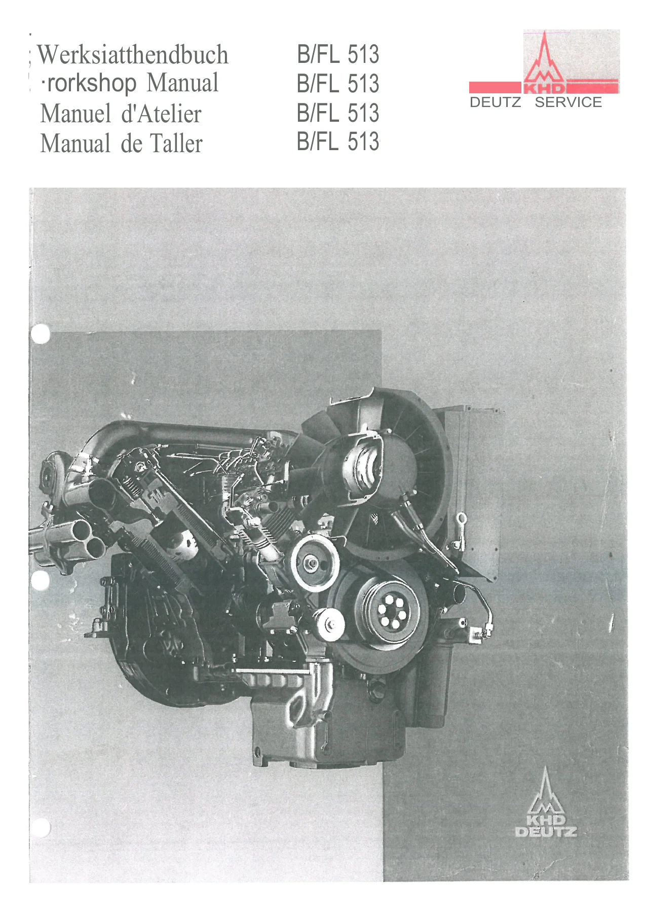
Deutz B/FL 513 Workshop Manual – F8L 513/L, F10L 513, F12L 513, BF8L 513/LC, BF10L 513, BF12L 513/C
Original price was: $44.95.$26.95Current price is: $26.95.
Comprehensive 612-page multilingual DEUTZ B/FL 513 workshop manual covering F8L 513/L, F10L 513, F12L 513, BF8L 513/LC, BF10L 513 and BF12L 513/C engines. Includes specification data, checks and adjustments, component repair, complete engine disassembly and reassembly, K1/K2 turbocharger repair information and workshop tool references.
Description
Deutz B/FL 513 Workshop Manual – F8L 513/L, F10L 513, F12L 513, BF8L 513/LC, BF10L 513, BF12L 513/C
This 612-page multilingual workshop reference for the DEUTZ B/FL 513 engine family concentrates on repair, adjustment, inspection, component reconditioning and complete-engine workshop operations. Procedures are supported by photographs, sectional drawings, circuit diagrams, technical-data tables and special-tool references.
The manual covers naturally aspirated and turbocharged 8-, 10- and 12-cylinder versions identified in its specification tables as F8L 513/L, F10L 513, F12L 513, BF8L 513/LC, BF10L 513 and BF12L 513/C.
File Details
- Manual type: Workshop Manual
- Brand / model family: DEUTZ B/FL 513
- Covered engine versions: F8L 513/L, F10L 513, F12L 513, BF8L 513/LC, BF10L 513, BF12L 513/C
- Languages: German, English, French and Spanish
- Page count: 612 pages
- File format: PDF
Chapters Covered
- 1. Specification Data
- General engine data and engine weights
- Fuel injection system: injection pump, governor, injection nozzle, commencement of fuel delivery and advance/retard unit
- Cylinder unit: cylinder head, valve guides, valve seat inserts, valves, valve springs, valve clearance and checking dimensions
- Cylinders, pistons and piston rings
- Motion parts: crankshaft, crankpins, main bearing journals, thrust bearing journal, main bearings and main bearing bore
- Connecting rods, camshaft and valve timing
- Lubrication system, lube oil pump and oil pressure
- Tightening specifications
- 2. Making Checks and Adjustments
- Valve clearance
- Compression pressure
- Top Dead Center (TDC)
- Checking and adjusting commencement of fuel delivery
- Injector testing and adjustment
- Exhaust thermostat checking, dismantling and adjustment
- Electro-hydraulic cooling fan control – EHG
- Electro-hydraulic cooling fan control with shutter control – EHGK
- Crankcase breather valve checking and repair
- Fuel injection pump testing
- 3. Repairing Components
- Cylinder head, cylinder and piston
- Connecting rod and rocker arm bracket
- Pushrods, pushrod cover tubes and tappets
- Lube oil pump and pressure relief valve
- Crankcase and camshaft bearing bushes
- Refacing the cylinder seating on the crankcase and replacing the main oil pipe
- Crankshaft, camshaft and flywheel
- Advance/retard unit, including the version for P-type injection pump
- Injector repair
- Hydraulic cooling fan – standard version and version with fan brake
- Fan drive gearing and torque limiter
- Crankshaft seal replacement at the flywheel end and auxiliaries-carrier end without dismantling the engine
- Removing and refitting the exhaust turbocharger and air compressor
- 4. Disassembly and Reassembly of Complete Engine
- Dismantling the engine
- Tappet bridge, piston cooling nozzles and oil pipe
- Checking installation accuracy of piston cooling nozzles
- Tappets, camshaft, crankshaft and bearings
- Pistons, connecting rods, cylinders and cylinder units
- Adapter housing, rear cover, shaft seal and flywheel
- Piston crown clearance and cylinder heads
- Lube oil pump, suction pump, auxiliaries carrier, oil filter bracket, oil pan and starter
- Injection pump bracket and advance/retard unit
- Cooling fan drive, air guide plates, pressurestat, oil return lines and valve gear components
- Injectors, vibration damper, V-belt pulley and cooling fan
- Engine oil cooler, crankcase breather valve, temperature-monitoring points and injection pump
- Fuel lines, injection lines, wiring harnesses, temperature regulator, intake pipe, exhaust manifold, generator and V-belts
- 5. Turbocharger
- Repair instructions for K1/K2 series turbochargers
- Dismantling, inspection, bearing-play checks and reassembly procedures
- Compressor housing, turbine housing, shaft and turbine-wheel assembly
- Turbocharger standard and special repair tools
- 6. Tools
- Commercial workshop tools
- Special tools for engine disassembly, measurement, testing and assembly
Together, these sections give a technician a single workshop reference for dimensional checks, wear limits, adjustment data, tightening values, fault tracing and the mechanical sequence needed to strip, inspect, repair and rebuild major B/FL 513 engine assemblies. The specification section is especially useful when measurements taken during overhaul must be compared with the manual’s stated standard dimensions, clearances and wear limits.
Technical Data for Accurate Engine Work
The Deutz B/FL 513 Workshop Manual – F8L 513/L, F10L 513, F12L 513, BF8L 513/LC, BF10L 513, BF12L 513/C contains model-by-model specification tables rather than only general repair descriptions. The engine data identifies four-stroke direct-injection diesel versions and provides dimensions and settings across the covered F8L, F10L, F12L, BF8L, BF10L and BF12L variants. Technical sections include cylinder and piston dimensions, valve and valve-seat data, valve-spring information, crankshaft and bearing measurements, connecting-rod data, camshaft and valve timing, lubrication-pump data and tightening specifications.
For workshop adjustment work, the manual gives standard cold valve clearances of 0.2 mm inlet and 0.3 mm exhaust, with separate post-repair settings of 0.3 mm inlet and 0.4 mm exhaust and an instruction to return to the standard clearance after 50 running hours. It also covers compression-pressure comparison, injector opening-pressure checks, fuel-delivery timing and oil-pressure checks. The lubrication data includes a low-idle minimum oil pressure and settings for pressure-control and safety-valve functions, while the tightening section provides specified torque values and, where required, tightening-angle sequences.
Checks, Adjustments and Diagnostic Procedures
The checking and adjustment chapter is built around real workshop tasks. Valve-clearance procedures explain engine positioning, valve overlap and the adjustment sequence. The compression test procedure explains how the measurement is prepared and interpreted, including comparison between cylinders rather than relying on an isolated reading. Top Dead Center is established with the specified cranking equipment before fuel-delivery timing work is carried out.
Fuel-system work is covered in practical detail. The manual shows how commencement of fuel delivery is checked and corrected, how an injector is dismantled, how its opening pressure is tested and adjusted, how tightness is checked, and how the spray and buzzing characteristics are assessed. It also provides an on-engine test for the injection pump’s delivery valve and pumping element.
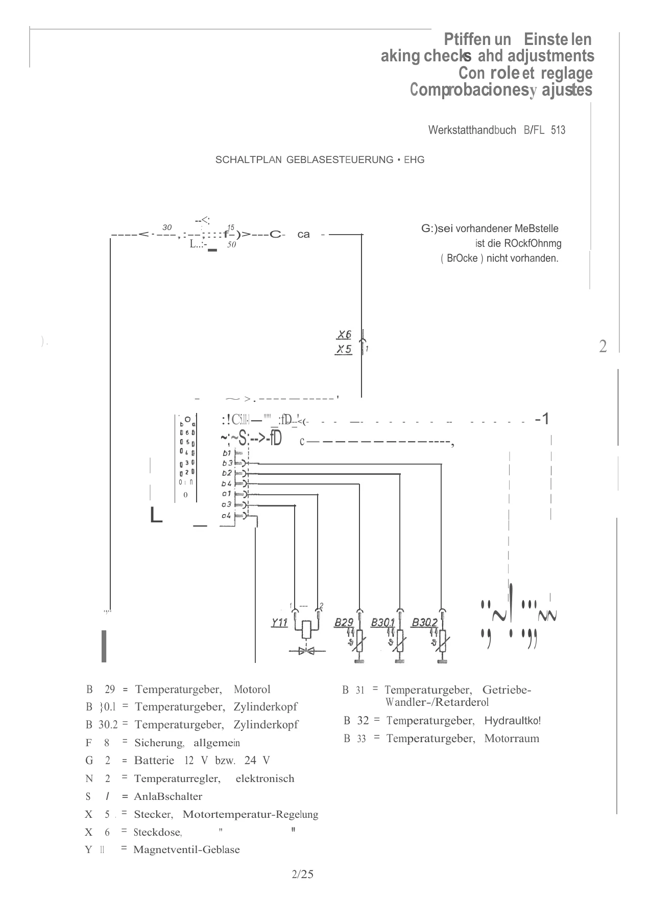
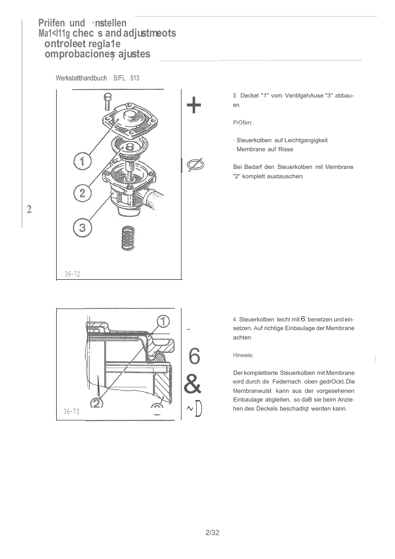
Cooling-system control diagnosis goes beyond mechanical inspection. The EHG and EHGK sections include test-procedure diagrams and electrical circuit diagrams for the electro-hydraulic cooling-fan controls. They identify the temperature sensors, solenoid valves, wiring connections and related control components used in the diagnostic process. The crankcase-breather section adds a pressure/vacuum check and a repair procedure for the valve and diaphragm assembly.
IMAGES PREVIEW
Component Reconditioning and Complete Engine Rebuild
For overhaul work, this workshop manual moves from measurement into repair. The component-repair chapter covers the cylinder head, cylinders, pistons, connecting rods, rocker gear, tappets, lubrication components, crankcase, camshaft bearings, crankshaft, camshaft and flywheel. It also includes procedures for the advance/retard mechanism, injectors, hydraulic cooling-fan assemblies, fan-drive gearing, torque limiter and crankshaft seals. Separate procedures address removal and refitting of the exhaust turbocharger and air compressor.
The complete-engine chapter provides the sequence for dismantling and rebuilding the engine, then breaks reassembly into identifiable groups such as piston cooling nozzles, oil pipe, tappets, camshaft, crankshaft and bearings, pistons and connecting rods, cylinder units, flywheel, cylinder heads, oil pumps, auxiliaries carrier, injection-pump components, cooling-fan drive, valve-gear parts, engine-oil cooler, fuel and injection lines, wiring harnesses, intake and exhaust components and generator drive. The manual repeatedly ties assembly operations to inspections, replacement seals, tightening requirements and special-tool use so the work can be followed in the intended order.
Turbocharger and Special Tool Reference
A dedicated turbocharger section supplies repair instructions for K1/K2 series units. It covers dismantling and assembly operations, checks on shaft and bearing condition, compressor and turbine housings, and the tools needed for the work. The final tools chapter then identifies commercial and special workshop equipment used throughout the B/FL 513 procedures, including compression and injection-pump test equipment, engine assembly fixtures, adapters, pullers, mandrels and other purpose-made service tools.
Important Manual Scope
This is a workshop repair and adjustment manual. The manual itself directs operating and routine maintenance information to the corresponding Operation Manual and directs spare-parts ordering to the appropriate parts catalogue. Buyers looking specifically for B/FL 513 repair procedures, measurement data, adjustments, component reconditioning and engine disassembly/reassembly will find those workshop subjects in this volume.
Repair, Measure and Reassemble with the Correct Reference
The Deutz B/FL 513 Workshop Manual – F8L 513/L, F10L 513, F12L 513, BF8L 513/LC, BF10L 513, BF12L 513/C supports major engine repair work from initial checks through component inspection and complete reassembly. It gives the procedures and technical values needed to check clearances, compare wear measurements, set valve and fuel-system adjustments, diagnose cooling-fan controls, service injectors, overhaul core engine components and rebuild the engine in the documented sequence. Using the stated specifications and tightening instructions matters because many of these jobs depend on precise dimensions, pressures, clearances and assembly steps. Your purchase is supplied as an instant PDF download after payment, with no shipping required; the file can be opened on compatible phones, tablets and computers and printed for workshop reference.
Reviews
There are no reviews yet.