

Deutz TCD 6.1 L6 Fendt 700 Vario SCR (3b) Workshop Service Manual PDF
Original price was: $44.95.$26.95Current price is: $26.95.
352-page workshop service manual for the DEUTZ TCD 6.1 L6 engine in the FENDT 700 Vario SCR (3b) application. Covers illustrated engine repair job cards, 1600 bar injection-system service, measurements and tightening data, wiring diagrams, sensors, exhaust-gas treatment, and standard/special tool references.
Description
Deutz TCD 6.1 L6 Fendt 700 Vario SCR Workshop Service Manual
The Deutz TCD 6.1 L6 Fendt 700 Vario SCR (3b) Workshop Service Manual PDF is a 352-page workshop service reference for the TCD 6.1 L6 engine in the FENDT 700 Vario SCR (3b) application shown on the manual cover. It is arranged around workshop job cards, with illustrated removal and installation procedures, inspection and measuring work, tightening data, setting values, tool references, fuel-system cleanliness requirements, electrical checks and wiring diagrams. The cover identifies the application as FENDT 700 Vario SCR (3b) and prints the coverage line 732 / 733 / 734 / 735 / 736 / 737 .. 1001-.
File Details
- Manual type: Workshop Service Manual
- Engine: DEUTZ TCD 6.1 L6
- Application: FENDT 700 Vario SCR (3b)
- Language: English
- Page count: 352 pages
- File format: PDF
- Front matter date: 07/2014
Workshop Job-Card Format
This manual is built around DEUTZ workshop job cards rather than a general owner’s guide. The introductory section explains the job-card numbering system, symbols, references, required conventional and special tools, auxiliary materials, test and setting data, and tightening specifications. Individual procedures then identify the assembly, required tools and materials, dismantling or installation sequence, cautions, component illustrations and the applicable technical data. This makes the manual especially useful when a repair has progressed beyond routine maintenance and accurate workshop steps are required.
Safety information is integrated into the repair material. The manual includes accident-prevention guidance, common-rail cleanliness measures, instructions for work on high-pressure fuel equipment and notes for exhaust-aftertreatment systems. It also explains that the engine installation can vary and that not every component described is necessarily installed in every application.
Chapters Covered
- Foreword, general and safety information
- Workshop manual use, job-card structure, symbols and safety requirements
- Common-rail cleanliness instructions and exhaust-aftertreatment handling
- Crankcase and front cover
- Crankcase bleeding, crankshaft sealing ring, shaft sleeve and front cover
- Piston cooling nozzles, oil filling and crankcase breather line
- Lubricating oil sump
- Removing and installing the die-cast lubricating oil pan
- Sealing procedure and tightening sequence
- Crankshaft and rotating components
- Torsional vibration damper, flywheel and toothed starter ring
- Crankshaft removal, inspection, axial clearance and crankshaft bearings
- Connecting rod
- Connecting-rod removal and installation
- Connecting-rod, liner and bearing checks with test and setting data
- Cylinder head
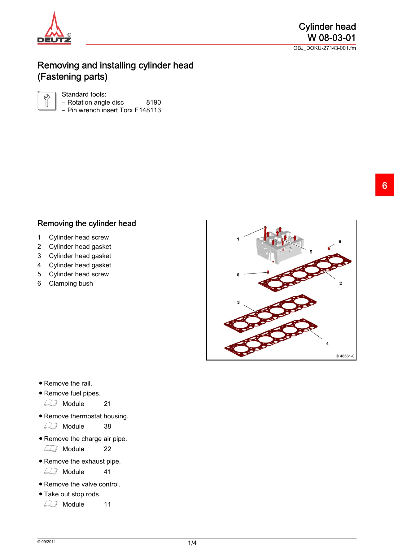
- Compression-pressure check, cylinder-head cover and cylinder-head removal/installation
- Piston overhang measurement, head-gasket selection and injector-sleeve renewal
- Gearcase
- Flywheel-side crankshaft sealing-ring renewal
- Valve control and control parts
- Valve-clearance checking and setting
- Valve-control removal, dismantling and assembly; tappets, stop rods and valve bridges
- Lubricating-oil cooler system
- Oil cooler and oil-cooler housing removal/installation
- Oil-filter add-on closing parts
- High-pressure fuel system
- High-pressure pump control block and high-pressure pump
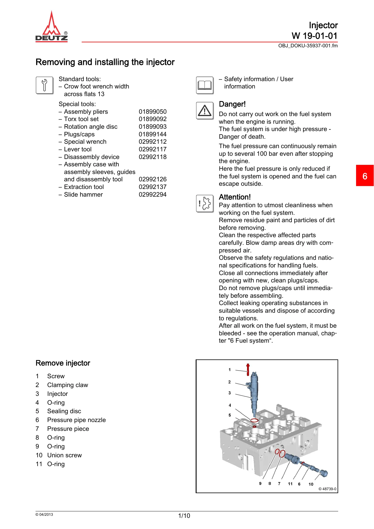
- Injector removal/installation and injector sealing components
- Fuel filter console, fuel supply pump and coupling plug
- Fuel pipes, return lines and the 1600 bar injection-system rail
- Charge-air system
- Charge-air line removal and installation
- Cooling and belt-drive components
- Coolant pump, thermostat-housing closing part, belt tensioner, carrier plate and fan bearing
- Exhaust and turbocharger
- Exhaust line removal/installation
- Exhaust-gas turbocharger removal/installation and mounting data
- Electrical and add-on components
- Generator V-rib belt pulley, console and starter
- Crankshaft and camshaft impulse transmitters, pressure/temperature sensor and temperature sensor
- Connection housing and start aid
- Connection-housing removal/installation
- Heating-flange disassembly and assembly
- Exhaust gas treatment
- NOx sensor removal/installation, holder and exhaust-gas temperature sensor
- Hydraulic pump drive
- Closing parts
- Wiring diagrams and electrical technical data
- Engine harness and equipment harness wiring diagrams
- Pressure, temperature and impulse-transmitter test data and pin assignments
- Workshop tools
- Standard-tool reference section
- Special-tool reference section with tool numbers and applications
Across these sections, the manual combines illustrated disassembly and assembly work with the measurements needed to judge component condition. Examples include crankshaft journal dimensions and run-out, crankshaft axial clearance, connecting-rod and bearing measurements, piston protrusion for cylinder-head-gasket selection, valve-setting data, staged fastener tightening and fuel-system installation requirements. The fuel-system material includes injectors, the high-pressure pump, control block, rail, lines and sensors, while the later pages add wiring information and electrical component test data. The Deutz TCD 6.1 L6 Fendt 700 Vario SCR (3b) Workshop Service Manual PDF therefore supports both mechanical overhaul work and system-level service checks.
Repair Data and Workshop Detail
The procedures are supported by extensive technical-data blocks. Crankshaft inspection includes main-journal and lifting-journal dimensions, hardness and permissible run-out; crankshaft axial clearance is given with the related thrust-ring checks. Connecting-rod pages cover piston-pin clearance, bearing clearance and permissible parallelism deviations. Cylinder-head work includes a compression-pressure comparison procedure, piston-overhang measurement and gasket selection, followed by specified tightening stages for cylinder-head installation.
Valve-train work gives the engine firing sequence and the rotation-angle method used to set inlet and exhaust valve clearance. The common-rail section provides detailed cleanliness precautions and job cards for high-pressure components, including the pump, injectors and rail. Injection and high-pressure lines are handled with specified installation alignment and tightening stages. The manual also includes a dedicated 1600 bar injection-system rail procedure, pressure-sensor and pressure-limiting-valve work, and fuel-system bleeding references.
Beyond the core engine, the manual covers the coolant pump, fan drive and bearing, charge-air line, exhaust line, turbocharger, generator pulley, starter and engine sensors. Exhaust-gas-treatment pages include NOx-sensor and exhaust-gas-temperature-sensor work. The electrical section includes engine-harness and equipment-harness wiring diagrams, followed by sensor and impulse-transmitter technical-data pages with pin assignments and measurement information. Standard and special tool catalogs at the end of the manual identify workshop tools by number and show their intended service use.
Illustrated Procedures, Measurements and Wiring
The visual job cards are an important part of the manual’s practical value. Component drawings, exploded views and workshop photographs show locations, orientation and the sequence of work for assemblies such as the front cover, crankshaft, connecting rod, cylinder head, injector, fuel rail and related lines. Many operations are followed by a dedicated Technical Data page so that the repair sequence and its tightening or setting information remain together. Procedures also call out parts that must be renewed after loosening or disassembly, surfaces that require particular cleanliness, and components that must be installed without tension or in a defined position.
The wiring section extends the coverage beyond mechanical work. The engine harness is presented across multiple sheets, with a separate equipment-harness diagram, and the following electrical technical-data pages support checks of pressure sensors, temperature sensors and impulse transmitters. This combination is useful when a fault investigation reaches the boundary between a mechanical component, its sensor and the engine wiring rather than ending at simple component replacement.
For Accurate TCD 6.1 L6 Workshop Repairs
The Deutz TCD 6.1 L6 Fendt 700 Vario SCR (3b) Workshop Service Manual PDF is suited to engine strip-down and reassembly, crankshaft and connecting-rod inspection, cylinder-head work, valve adjustment, injector and high-pressure fuel-system service, cooling-system component replacement, turbocharger and exhaust work, sensor service and electrical diagnosis using the included wiring information. Correct sequences, tightening stages, measurement limits, installation positions and tool references matter when engine components are being reused, replaced or adjusted, and this manual places those workshop details alongside the relevant repair steps.
Purchase provides instant PDF delivery with no shipping delay. Open the manual on a computer, tablet or phone, keep it available in the workshop, and print the pages needed for a specific repair or inspection job.
IMAGES PREVIEW
Reviews
There are no reviews yet.