
DEUTZ TCD 7.8 L6 Workshop Service Manual — Fendt 900 Vario SCR (St3b) 941-946 PDF
Original price was: $64.95.$39.95Current price is: $39.95.
Complete DEUTZ TCD 7.8 L6 Workshop Service Manual for Fendt 900 Vario SCR (St3b) 941/942/943/944/945/946. 222 pages of job-card repair procedures, torque specifications, testing data and wiring diagrams. Instant PDF download.
Description
DEUTZ TCD 7.8 L6 Workshop Service Manual — Fendt 900 Vario SCR (St3b) 941–946
This is the complete DEUTZ Workshop Service Manual for the TCD 7.8 L6 engine as installed in the Fendt 900 Vario SCR (St3b) series, covering models 941, 942, 943, 944, 945 and 946 from serial number 1001 onward. Written for the professional technician, it lays out the factory job-card procedures, tightening torques, testing and setting data, and special tool requirements needed to service, repair and overhaul this six-cylinder common-rail diesel engine.
The manual is structured around DEUTZ job cards — each card documents a specific repair with step-by-step workflow, illustrated assembly and disassembly views, and the exact torque figures and measurement tolerances for that operation. Whether you are resealing a front cover, replacing a crankshaft sealing ring, pulling a high-pressure pump, or diagnosing a NOx sensor fault, the procedure and the specifications are here.
File Details
- Manual type: Workshop Service Manual (job cards W and I)
- Engine: DEUTZ TCD 7.8 L6
- Equipment: Fendt 900 Vario SCR (St3b)
- Models covered: 941, 942, 943, 944, 945, 946 (serial 1001–)
- Language: English / German
- Page count: 222
- File format: PDF
- Document numbers: 0421 8098, 0421 7560, 0440 9013
Chapters Covered
The manual opens with foreword, general information and a comprehensive safety section before moving into the job-card-based repair procedures.
Safety Information and User Information
Accident prevention and safety regulations for working on common-rail fuel systems operating at up to approximately 2000 bar. Cleanliness instructions and measures for working with common-rail systems, including workshop area requirements, workbench and tool rules. Additional information and measures for handling exhaust aftertreatment systems — DPF, ignition system and SCR (AdBlue). Disposal regulations. Explanation of symbols and job card structure.
Crankcase Breathing and Crankcase Breather
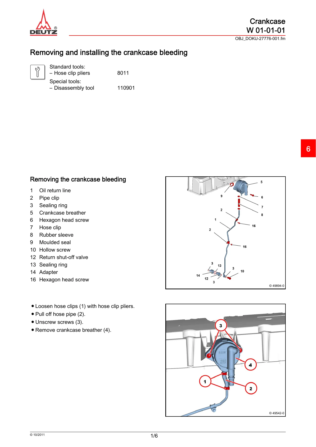
Removal and installation of the crankcase breather on the cylinder head cover, including hose clip, pipe clip, moulded seal and return shut-off valve procedures. Torque values for the crankcase breather (30 Nm), return shut-off valve (29 Nm) and pipe clip fastening (13 Nm).
Crankshaft Sealing Ring and Shaft Sleeve
Complete procedure for renewing the crankshaft sealing ring, including removal with pricker and assembly lever, visual inspection of the running surface, and installation using guide sleeve, assembly sleeve and installation depth shims. Assembly and disassembly of the shaft sleeve on the crankshaft, including packing compound DEUTZ DW 74 and impact sleeve procedure.
Front Cover
Removing and installing the front cover with fastening parts, gasket, clamping bush and packing compound. Tightening sequence and torque specification (30 Nm).
Crankshaft Bearings
Removal and installation of crankshaft bearings, including shim halves, upper and lower main bearing shells, thrust ring halves, and bearing shell assignment. Measurement of main bearing diameter (85.05–85.07 mm internal), theoretical radial clearance (0.030–0.090 mm) and thrust washer wall thickness (2.9 +0.05 mm standard, 3.1 +0.05 mm overmeasure).
Piston Cooling Nozzles
Removal and installation of piston cooling nozzles in the crankcase, with torque specification (21 Nm).
Crankshaft
Removal and installation of the crankshaft, including marking procedures for the camshaft gear wheel, axial backlash check, and the sequence for installing crankshaft bearing covers. Covers the threaded insert and the alignment markings that must be in line.
Piston and Piston Rings
Removal and installation of the piston, piston pin, locking rings and connection rod. Attention to the arrow on the big end bearing cover and the flywheel/crankshaft symbol. Checking piston rings — joint clearance (ring 1: 0.30–0.40 mm, ring 2: 0.65–0.90 mm, ring 3: 0.35–0.65 mm) and ring height. Piston ring dimensions (ring 1: 110/100.9 x 3 mm, ring 2: 110/100.9 x 2 mm, ring 3: 110/101.7 x 3.5 mm).
Cylinder Head Cover
Removing and installing the cylinder head cover, gasket and screws. Tightening sequence with 9 Nm specification.
Piston Overhang and Cylinder Head Gasket Selection
Checking piston overhang with dial gauge, measuring beam and liner holder. Selection of cylinder head gasket based on measured piston projection: 1-hole gasket (1.15 mm) for 0.080–0.300 mm, 2-hole gasket (1.25 mm) for 0.301–0.495 mm.
Valves
Removal and installation of valves using support bracket, base plate, assembly lever and assembly tool. Checking valve stem diameter (inlet 7.965 -0.015 mm, exhaust 7.955 -0.015 mm), valve head diameter (inlet 38.2 +0.1 mm, exhaust 35.8 +0.1 mm), valve guide (8.000 +0.022 mm), valve stem clearance (inlet 0.035–0.072 mm, exhaust 0.045–0.077 mm), valve spring length (67.4 mm) and valve lag (1.15 +0.25 mm).
Injector Sleeve
Removal and installation of injector sleeves, including thread drilling, threaded spindle, hold-down device and conical pin. Pay attention to utmost cleanliness. Procedure for both loose and tight injector sleeves.
Camshaft
Checking the camshaft — visual inspection of cams and bearing pins, camshaft gear wheel check, and measurement of bearing pin diameter (73 -0.05 mm).
Lubricating Oil Cooler Housing
Removal and installation of the lubricating oil cooler housing with seals and hexagon head screws. Torque specifications — M8 screws: 30 Nm, M10 screws: 60 Nm, with Stage 1 of 3 Nm and tightening sequence.
Control Block
Removal and installation of the control block, including dismantling and assembling with overflow valve, solenoid valve, throttle and O-rings. Torque values — control block on crankcase: 20 Nm, solenoid valve: 4.5 Nm, throttle: 12 Nm, overflow valve: 33 Nm.
High-Pressure Pump
Removal and installation of the high-pressure pump, including roller tappet removal with special pliers, assembly guide and O-ring installation. Torque specification — Stage 1: 10 Nm, Stage 2: 50 Nm.
Fuel Lines and High-Pressure Lines
Removal and installation of fuel lines (control block – high-pressure pump), fuel supply lines, fuel filter, control block, rail and cylinder head lines. Torque values for union nuts (28 Nm), hollow screws (39 Nm), pipe screw connections and fuel line installation angles.
Rail and Injection Pipes
Removing and installing the rail with pressure sensor and pressure limiting valve. Removing and installing injection pipes and high-pressure lines. Torque specifications — rail on cylinder head: 30 Nm, pressure limiting valve: 110 Nm, pressure sensor: 70 Nm. Injection line union nuts — Stage 1: 10 Nm, Stage 2: 60° + 15°.
Vibration Damper
Installation position of vibration damper for high-pressure lines, with dimension specifications (62½ mm and 17 ±1 mm) and access requirements for special tools.
Thermostat Housing
Removal and installation of the thermostat housing, plug element, seal and hexagon head screws. Torque specification: 30 Nm.
Temperature Transmitter (Exhaust Gas)
Removal and installation of the exhaust gas temperature transmitter, with torque specification of 45 Nm and locking screw of 32 Nm.
Lubricating Oil Line (Exhaust Turbocharger)
Removal and installation of the lubricating oil line on the exhaust turbocharger, including hollow screws, sealing rings and pipe clips. Torque specification: 39 Nm for hollow screws, 30 Nm for pipe clips.
V-Rib Belt Pulley
Removal and installation of the V-rib belt pulley on the generator, including clamping cone, washer and hexagonal nut. Torque specification: 75 Nm.
Starter
Removal and installation of the starter, including battery negative terminal disconnect, cable plug and cable ties. Torque specification: 60 Nm.
NOx Sensor
Removal and installation of the NOx sensor with claw wrench and fitting compound DEUTZ S1. Torque specification: 50 Nm. Sensor assignment and cable laying with safety loop.
Sensors and Transmitters
Technical data and testing for pressure sensors, temperature sensors, impulse transmitters and their pin assignments. Includes switching diagrams, measuring ranges, resistance values at various temperatures, and diagnostics tables.
Wiring Diagrams
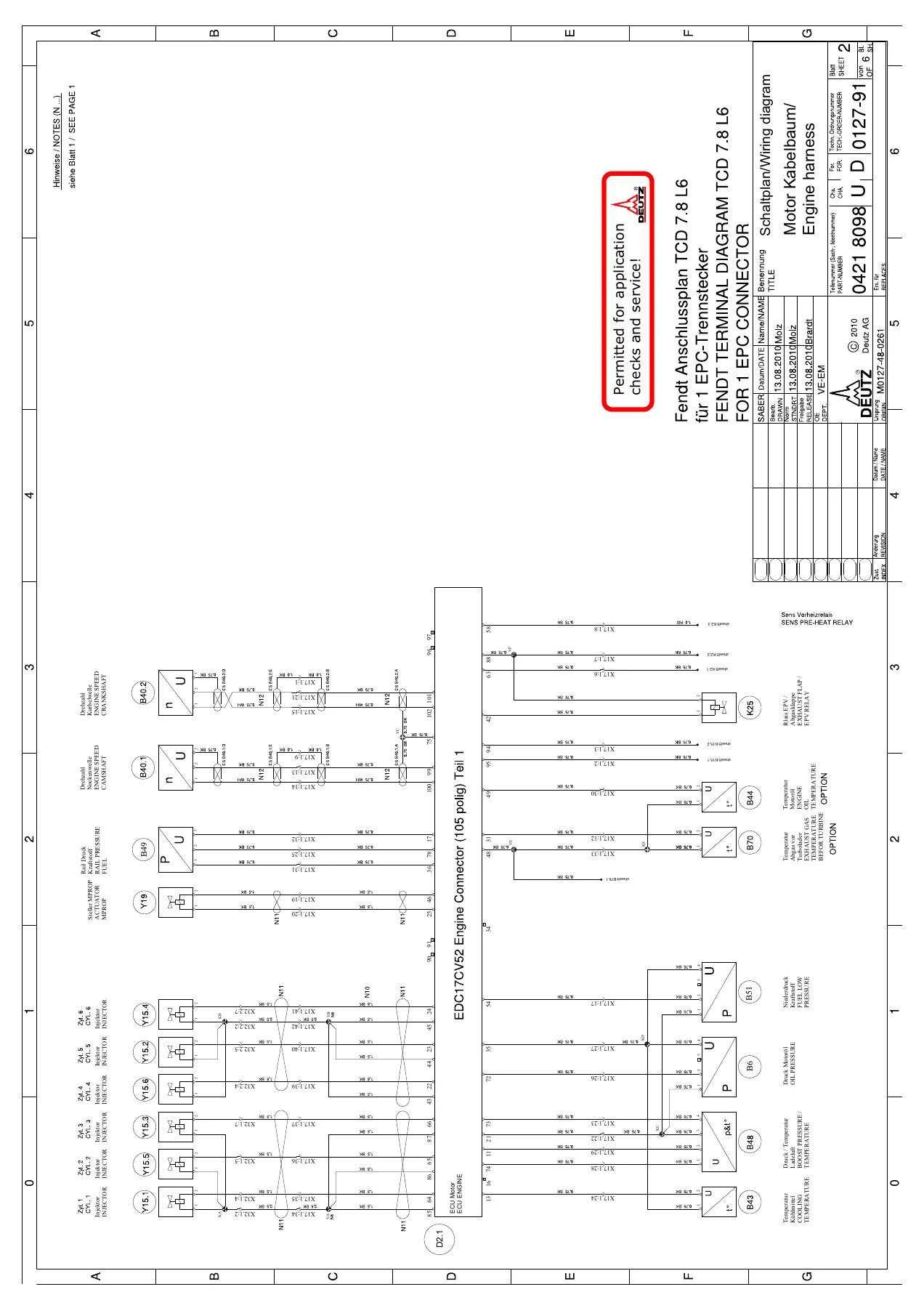
Complete engine harness (0421 8098, 6 sheets), equipment harness (0421 7560, 1 sheet) and exhaust aftertreatment harness (0440 9013, 4 sheets) wiring diagrams in English and German.
Standard Tools and Special Tools
Illustrated catalogue of conventional tools and special tools required for the procedures in this manual, including pressure pumps, assembly sleeves, compression testers, hose clip pliers, socket wrench inserts, Torx tools, rotation angle disc, dial gauges, turning gears, pullers, support brackets and more. Each tool is listed with its order number.
Technical Data Throughout
Every job card is followed by its own Technical Data page with tightening specifications and testing/setting data. These tables give the exact torque values, wear limits, clearances and adjustment figures needed to complete each repair to factory specification. The manual covers tightening torques for the crankcase breather, return shut-off valve, pipe unions, front cover, piston cooling nozzles, cylinder head cover, oil cooler housing, control block, high-pressure pump, fuel lines, rail, injection lines, pressure sensor, pressure limiting valve, thermostat housing, exhaust temperature transmitter, lubricating oil line, V-rib belt pulley, starter and NOx sensor.
Why This Manual Matters
The DEUTZ TCD 7.8 L6 is a high-precision common-rail engine. The fuel system operates at pressures up to approximately 2000 bar, and the exhaust aftertreatment system includes both DPF and SCR components. Working on these systems without the correct procedures, cleanliness protocols and torque figures risks component damage, fuel system contamination and personal injury. This workshop manual gives you the manufacturer’s own job-card workflows, the safety regulations that apply, and the exact specifications — so every repair is done once, done right.
With 222 pages covering engine mechanical, fuel injection, cooling, lubrication, electrical and exhaust aftertreatment systems, this is the reference the professional technician needs for the Fendt 900 Vario SCR (St3b) 941 through 946 with the DEUTZ TCD 7.8 L6 engine.
IMAGES PREVIEW
Instant PDF Delivery
The manual is delivered as an instant PDF download — no shipping, no waiting. Open it on any device: laptop, tablet or smartphone. Print the pages you need for the workshop and keep the digital copy for quick reference. Every job card, every torque table, every wiring diagram is at your fingertips the moment you complete checkout.
Reviews
There are no reviews yet.