
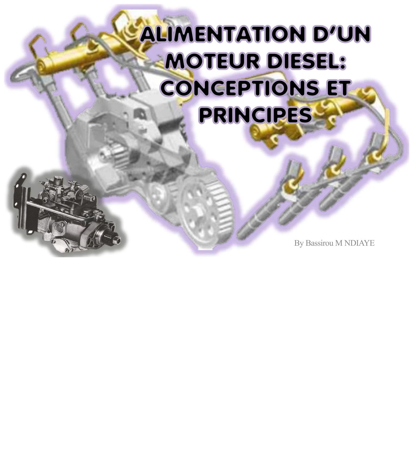
Diesel Engine Fuel Supply & Injection Systems Technical Training Manual
Original price was: $34.95.$20.95Current price is: $20.95.
128-page technical training manual covering diesel engine fuel supply and injection principles, including inline injection pumps, Bosch VE rotary distributor pumps, injector-pump systems, common rail fuel systems, high-pressure pumps, injectors, fuel pressure control, fuel cooling and SCR/AdBlue systems. Illustrated throughout with component diagrams, operating sequences and system schematics.
Description
Diesel Engine Fuel Supply & Injection Systems Technical Training Manual
The Diesel Engine Fuel Supply & Injection Systems Technical Training Manual is a detailed 128-page training reference explaining how diesel fuel travels from the tank to the combustion chamber and how several generations of diesel injection equipment create, control and distribute injection pressure. Rather than concentrating on one vehicle or one engine, the manual develops the subject from basic diesel-engine operation through mechanical inline and rotary pumps, injector-pump systems and electronically controlled common rail equipment.
The material is heavily illustrated with sectional drawings, flow diagrams, component layouts and step-by-step operating sequences. It is useful for understanding the relationships between the low-pressure supply circuit, high-pressure generation, injectors, pressure regulation, fuel return and electronic control components. Later sections extend the coverage into fuel cooling, pressure sensors, modern high-pressure pumps, common rail injectors and selective catalytic reduction equipment.
File Details
- Manual type: Technical training manual
- Subject: Diesel engine fuel supply and injection systems
- Language: English with some French terminology and labels in illustrations
- Page count: 128 pages
- File format: PDF
- Author shown: Bassirou M NDIAYE
From Basic Fuel Supply to High-Pressure Injection
The training begins with a review of the diesel combustion cycle and the purpose of the fuel supply system. It identifies the reservoir, low-pressure or feed pump, filter, high-pressure injection pump, injector, return circuit, sensors and actuators. The manual distinguishes the low-pressure circuit running from the fuel tank through filtration to the high-pressure pump from the high-pressure circuit carrying pressurized fuel to the injectors.
The role of filtration is also explained, including removal of suspended impurities and water, while the return system is shown as both a path for excess fuel and a means of cooling injection-system components. A useful early diagram presents the complete relationship between the tank, filter, low-pressure pump, high-pressure pump, injector and combustion chamber before the manual moves into individual injection architectures.
Mechanical Inline Injection Pump Operation
A substantial section of the Diesel Engine Fuel Supply & Injection Systems Technical Training Manual examines the inline injection pump. Diagrams identify pump elements, the regulator, supply pump, residual-pressure valve, discharge fittings, pump cylinders, discharge valves, inlet and discharge ports, helical ramps, displacement pistons, springs, roller pushrods and cams.
The operating sequence follows fuel through aspiration, pressure generation and delivery. The manual explains that each engine cylinder has a corresponding pump element and shows how the camshaft-driven piston produces injection pressure. It then illustrates how piston rotation, the rack, toothed sector, groove and helical ramp alter effective pumping duration and therefore the injected fuel quantity. Multiple sectional illustrations make the relationship between piston movement, port opening and fuel metering easier to visualize.
Rotary Distributor and Bosch VE Injection Pumps
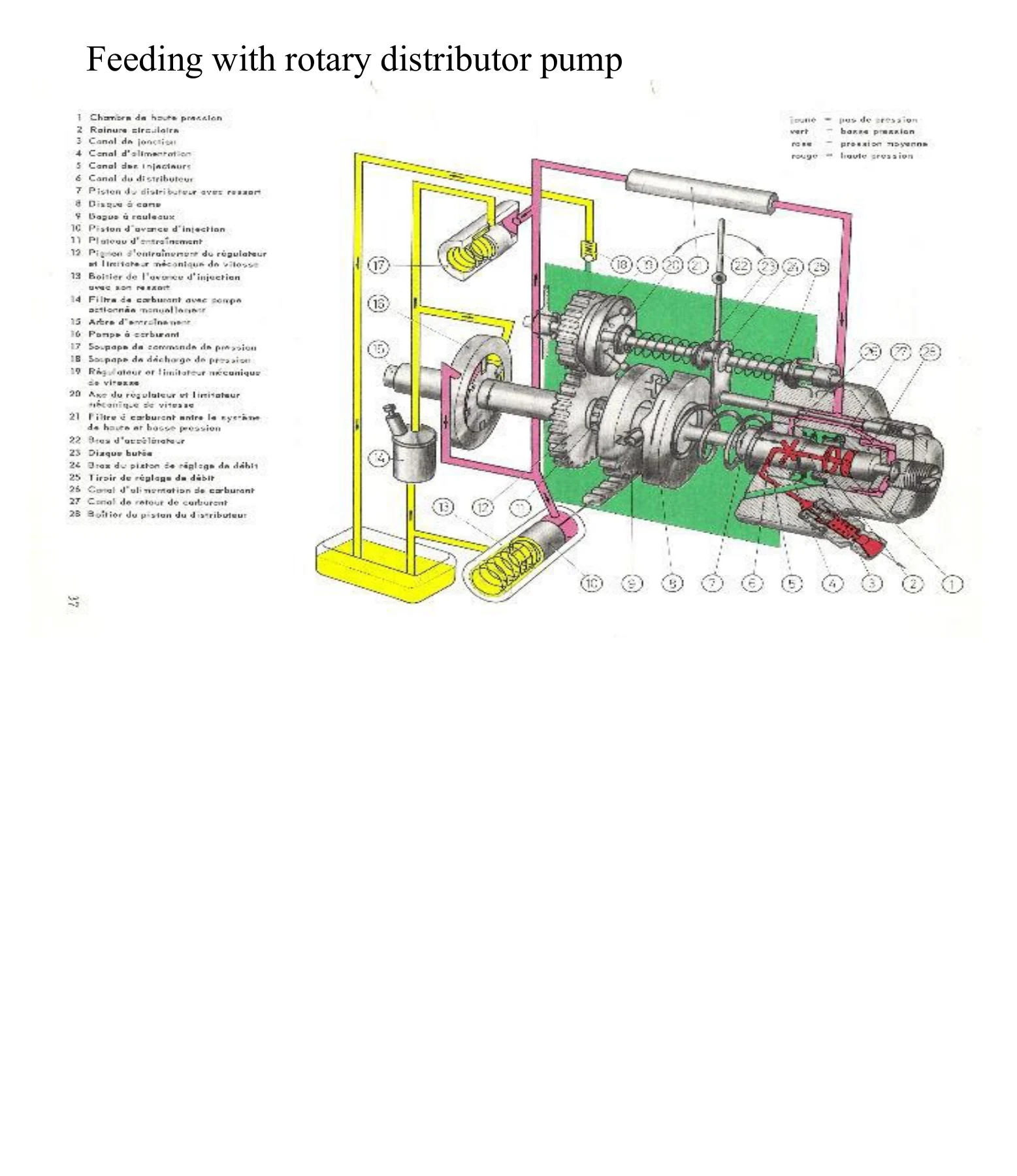
The rotary distributor section introduces several pump arrangements before concentrating on Bosch VE construction and operation. Internal components shown include the drive shaft, transfer pump, centrifugal governor, shut-off solenoid, hydraulic head, cam plate and flow-control components.
The transfer-pump section explains low-pressure supply inside the injection pump and the need for pressure regulation. The hydraulic-head material then shows high-pressure generation, distribution to individual cylinders, engine shut-off and operating-speed regulation. Detailed diagrams identify the distributor piston, flow ring, supply channel, pressure chamber, central channel, discharge connection and high-pressure passages.
Sequential illustrations show filling, high-pressure pumping and injection. Other pages explain the centrifugal governor with weights, the electrically operated shut-off solenoid and the advance piston used to vary injection timing. The manual also illustrates later electronically controlled developments of the rotary distributor pump.
Injector-Pump Systems
The next major section moves to injector-pump technology, where pressure generation and injection take place in a unit mounted at the cylinder head. The manual compares this arrangement with distributor-pump systems and lists advantages including finer atomization, reduced injection delay, more precise injection start, reduced emissions, lower fuel consumption, higher power output and smoother combustion through pre-injection.
Illustrations show injector-pump construction, mounting position, the injection cam and roller rocker arrangement, fixing methods and internal parts such as the pump piston, piston spring, solenoid needle, fuel return, high-pressure chamber, injector spring and injector needle. The training material also explains hydraulic damping of the injector needle and the exhaust piston used to reduce injection noise.
A sequence of operating diagrams follows the injector-pump cycle through filling of the pressure chamber, beginning and completion of pre-injection, beginning and completion of main injection, and return-fuel functions. Fuel return is associated with injector cooling, evacuation of leakage and removal of vapor bubbles.
Fuel Supply, Tandem Pump and Cooling
Fuel supply around the injector-pump system is treated as its own system. The diagrams identify pressure-limiting valves, fuel filters, check valves, fuel coolers and the tank. Tandem-pump pages separate the vacuum-pump and fuel-pump functions and illustrate internal pressure regulation and fuel flow between the tank, pump, cylinder head and return circuit.
The cylinder-head distribution tube is shown serving multiple cylinders while separating incoming cold fuel from heated return fuel. Separate fuel-cooling diagrams illustrate a cooler, fuel-temperature transmitter, expansion tank, auxiliary water radiator and fuel-cooling pump, followed by an example of an underbody fuel cooler.
Common Rail Diesel Injection
The common rail section presents first-, second- and third-generation system layouts, showing the evolution of fuel supply, high-pressure generation, the common rail and injectors. The electric fuel-supply unit is broken down into its rotor, stator, windings, pre-supply pump and electrical connections, with additional diagrams explaining regulated fuel-pump operation.
Fuel filter heating control is illustrated at 5 °C and 35 °C. The manual then covers the N290 fuel-metering valve in Bosch, Delphi and Continental arrangements, including activated and non-activated operating states.
The high-pressure pump section specifically illustrates the Bosch CP4.1, identifying its suction valve, discharge valve, pump piston, N290 fuel-metering valve, cam-driven shaft and overflow valve. Separate diagrams trace both the suction stroke and discharge stroke.
Rail-side components include the G247 fuel-pressure transmitter with its strain gauge and steel membrane, plus N276 fuel-pressure regulator valves in Bosch/Delphi and Continental arrangements. A return-pressure retention valve is also shown, with the manual explaining its purpose of generating and maintaining pressure in the injector return circuit.
Common Rail Injector Operation and Adjustment
The injector section provides a general sectional view showing rail pressure, return pressure, control valve, restrictions, injector spring and needle. The operating principle is then illustrated with separate closed-injector and open-injector conditions using pressure relationships on either side of the needle-control system.
The manual also identifies Bosch injector correction information, including IMA for injector flow adjustment and ISA for injector pressure adjustment. Another page introduces an internal cylinder-pressure transmitter arrangement incorporating sensing electronics, a strain gauge and a pressure-measurement membrane.
Selective Catalytic Reduction and AdBlue Systems
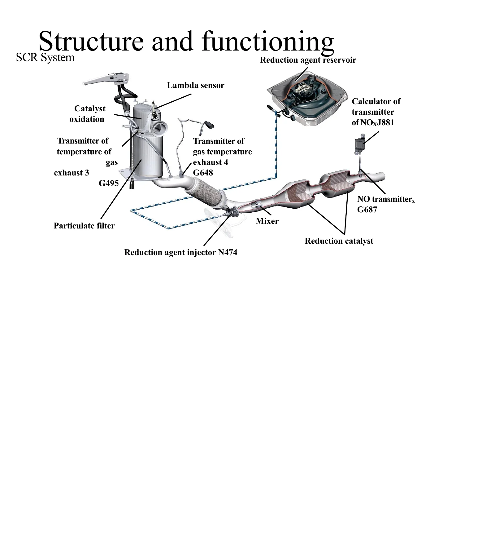
The final technical section broadens the training into selective catalytic reduction. It identifies the reducing-agent reservoir, oxidation catalyst, particulate filter, temperature transmitters, NOx transmitter, mixer, reduction catalyst and N474 reducing-agent injector. Diagrams illustrate system structure, tank level sensing and the relationship with the engine controller and instrument display.
The manual explains AdBlue handling precautions and shows how contamination can affect the system. It also illustrates the thermolysis, hydrolysis and NOx-reduction stages in the exhaust aftertreatment path. Several pages demonstrate instrument-cluster warnings for low AdBlue level and system faults, including warnings associated with remaining ranges of 2400 km, 1000 km and 0 km.
Special workshop equipment illustrated at the end includes the VAS 6542 AdBlue filling device, V.A.G. 1383A/1 support plate and VAS 6557 SCR vacuum box.
Chapters Covered
- Principle of operation of the diesel engine
- Diesel engine fuel supply principles
- Common fuel-system components
- Fuel tank, low-pressure pump and filter
- High-pressure pump and injector functions
- Return circuit
- Sensors and actuators
- Inline pump fuel system
- Inline injection pump construction
- Aspiration, pressure and delivery
- Injection quantity control and helical-ramp metering
- Rotary distributor pump fuel system
- Bosch VE injection pump construction
- Transfer pump
- Hydraulic head
- Filling, high-pressure delivery and injection
- Centrifugal governor
- Shut-off solenoid
- Injection advance piston
- Evolution of rotary distributor injection pumps
- Injector-pump fuel system
- Injector-pump construction and mounting
- Injection cam
- Injector needle damping
- Injector-pump operating cycle
- Pre-injection and main injection
- Fuel return and injector cooling
- Tandem pump and fuel supply
- Cylinder-head fuel distribution
- Fuel cooling
- Common rail diesel injection
- First-, second- and third-generation layouts
- Electric fuel supply pump
- Fuel filter heating
- N290 fuel-metering valve
- Bosch CP4.1 high-pressure pump
- Fuel pressure transmitter G247
- N276 fuel-pressure regulator valve
- Return pressure retention valve
- Common rail injector operation
- Injector flow and pressure adjustment references
- Selective catalytic reduction
- AdBlue handling
- SCR components and system operation
- AdBlue level and fault displays
- SCR workshop tools
Taken as a whole, the manual provides a visual technical progression from conventional mechanically controlled diesel injection to electronically managed injector-pump and common rail systems. It is particularly useful for studying how fuel pressure is created, regulated and distributed, how injection quantity and timing are controlled, and how supporting systems such as fuel cooling and SCR interact with modern diesel powertrains.
Build a Stronger Working Knowledge of Diesel Injection Systems
The Diesel Engine Fuel Supply & Injection Systems Technical Training Manual can support technicians, students and experienced owners who need to understand fuel-system architecture before diagnosing or servicing diesel injection equipment. Its sectional drawings and operating sequences help connect individual components with what is happening to fuel pressure, flow, timing and injector operation throughout the system.
Correct understanding of these systems matters because mechanical pumps, electronically controlled injector-pumps and common rail systems achieve injection in very different ways. Having the operating principles, component layouts, pressure-control devices and fuel-flow paths available in one reference can make fault tracing and technical study much more systematic.
IMAGES PREVIEW
This is an instant PDF download with no physical shipping required. Save the file to your computer, tablet or phone for convenient access, and print the pages you need for training, workshop reference or system study.
Reviews
There are no reviews yet.