Dongfeng DFA1101GZAD6J-907 Truck Service Manual – PDF DOWNLOAD
$27.95
Dongfeng DFA1101GZAD6J-907 Truck Service Manual – PDF DOWNLOAD
Description
Dongfeng DFA1101GZAD6J-907 Truck Service Manual – PDF DOWNLOAD
FILE DETAILS:
Dongfeng DFA1101GZAD6J-907 Truck Service Manual – PDF DOWNLOAD
Language :English
Pages :175
Downloadable : Yes
File Type : PDF
IMAGES PREVIEW OF THE MANUAL:
DESCRIPTION:
Dongfeng DFA1101GZAD6J-907 Truck Service Manual – PDF DOWNLOAD
General Principles
- This manual mainly states maintenance and service methods of DFA1101GZ5AD6J-907 light commercial truck.
- To use vehicles safely and efficiently, you need to read the manual thoroughly and make sure that you are familiar with the items that mark “Note”. This is very important.
- Due to continuous improvements on our vehicles, maybe there are some instructions in the manual that do not accord with the actual vehicles.
- Maintenance method varies with different skill level, methods, tools and available parts that serviceman adopts.
- Any serviceman should firstly take into consideration no harm personal safety and vehicle safety when working.
- As for the maintenance of engine, please refer to service documents offered by DongFeng Cummins Engine Co., Ltd.
TABLE OF CONTENTS:
Dongfeng DFA1101GZAD6J-907 Truck Service Manual – PDF DOWNLOAD
DFA1101GZ5AD6J-907 Service Manual 1
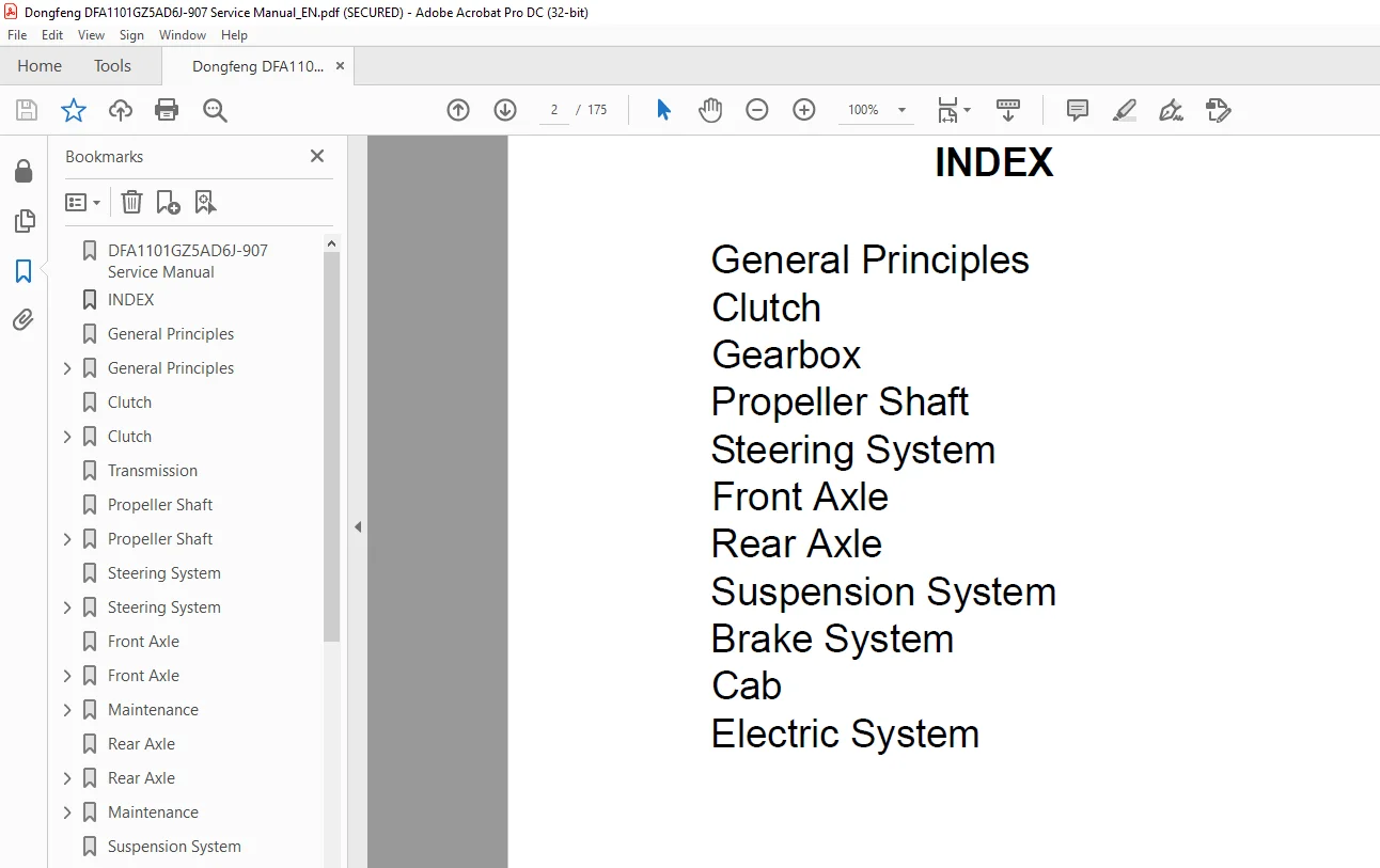
INDEX 2
General Principles 3
General Principles 4
Operational Instruction 5
Standard Terms 5
Standard Tightening Torque 5
Maintenance Rule 6
Recommended Fuel and Lubricant 9
Protective Measures while Repairing 11
Cleaning 12
General Inspection 12
Trouble Analysis 13
Clutch 16
Clutch 17
Main Parameter 17
Clutch Mechanical System 19
Adjustment of Clutch Pedal 20
Clutch Cover and Flywheel 22
Usage and Maintenance 23
Transmission 25
Propeller Shaft 64
Propeller Shaft 65
Technical Parameter 65
Maintenance Standard 65
Tightening Torque 65
Trouble Analysis 65
Propeller Shaft 66
Structure 66
1 Flange fork 66
Intermediate Propeller and Center Bearing 67
Structure 67
1 Flange fork 67
Propeller Shaft Maintenance 67
1 Support the rear axle up 67
2 Turn the propeller shaft, and check one point of the propeller shaft for its radial runout 67
3 If the radial runout is above the limit value, remove the connecting flange of one end of the rear axle, and turn it for 18 68
4 Check the radial runout again, if it still beyond the limit value, replace the propeller shaft 68
5 Road tests 68
1 Make marks on the propeller shaft and flange fork 69
2 Remove the snap ring 69
3 Knock the flange fork with a hammer, and don’t damage the holes of the spider shaft and flange fork when disassembling the spider shaft 70
4 Disassemble the spider shaft bearing of the other end in the same way Make marks on the dismantled parts, and you may not change their original position when reassembling 70
1 Install the spider shaft bearing, apply some grease on the surface of the bearing inside face 70
2 Select a snap ring to make the spider shaft among the required axial clearance and install it The thickness of the selected snap ring should be below 006mm 70
3 Eliminate the clearance between bearing and snap ring by knocking flange fork 71
4 Check the flexibility and axial freedom of the spider shaft 71
Maintain 71
1 Remove the propeller shaft 71
2 Loose the end face nut 71
3 Remove the connecting flange 71
4 Remove the front oil seal 71
5 Apply some grease on the lip cavity of the oil seal and then press it into the oil seal seat 72
6 Assemble the flange disc and drive gear nut 72
7 Assembly the propeller shaft 72
Disassembly and Assembly 72
Steering System 73
Steering System 74
Check 74
Steering Wheel and Steering Column 75
1 Steering wheel assy 75
Steering column 76
Disassembly and Assembly 76
Power Steering Hydraulic Pressure System 78
1 Power steering gear assembly 78
Steering Gear 79
Maintenance 79
1 After 2,500km, the new power steering gear need to replace its hydraulic pressure oil, and wash the filter in the oil reservoir Replace the hydraulic pressure oil and wash the filter ever 50,000km or every year after that 79
2 Check the oil quantity every month to see whether it reduced, deteriorated or too much impurities If there is any badness, you have to refill or replace the oil immediately 79
3 Check and keep the tire pressure accord with the requirement 79
4 Procedure of replace or fill oil 79
Trouble Analysis 80
Front Axle 82
Front Axle 83
Structure 83
Front axle, steering knuckle 83
1 Upper cover–steering knuckle 83
Disassembly of the Front Brake 84
1 Front dustproof shield 84
Maintenance 85
First maintain 85
1 Dismantle and check the wheel hub for any abnormal wear (please go to the Assembly and Adjustment to see the reference) 85
2 Check the fastening piece 85
Periodical maintain 85
1 Add some grease to the grease nipple 85
2 Avoid important nut loosed 85
3 Adjust wheel hub bearing pretightening force and toe-in 85
4 Adjust the brake clearance 85
Periodical Maintain Schedule 85
Assembly and Adjustment 86
Disassemble and asseble of the assembly 86
1 Fixed the front axle and remove the wheel hub end cover; 86
2 Take off the cotter pin, adjusting nut and spacer; 86
3 Turn the wheel hub brake drum a little and pull it, gently knock at the brake drum at the same time to loose the inner ring o 86
Adjustment of axle 86
1 Installl the steering knuckle and thrust bearing on teh front axle, select the proper adjusting spacer(Note:only use one) t 86
2 Apply a layer of grease on the surface of the kingpin, align the lock pin slot of the kingpin to the lock pin hole of the front axle, then insert the kingpin and tighten the lock pin; 86
3 Before add the grease, measure both left and right of the starting force at cotter pin of steering knuckle journal, and the 86
1 Apply some 2# lithium grease on the thread of the steering knuckle shaft end and the wearproof spacer; 86
2 Tighten the locking nut by a torque of 120~150Nm; 86
3 Turn the wheel hub for 2~3 circles to correct the alignment of the bearing; 86
4 Tighten the locking nut by a torque of 120~150Nm; 86
5 Unscrew the locking nut for 1/3 circle, install the locking washer and limit spacer, and make the limit spacer align to the steering knuckle key slot and the adjusting nut limit pin; 86
6 Install the outer nut, tighten it with a torque of 120~150Nm; 86
7 Make sure if the pretightening force is correct First, turn the wheel hub for 2~3 circles, then confirm the tangential force of the wheel hub bolt; 86
1 First, loose the locking bolt of the tie rod; 86
2 Turn the tie rod and make the toe-in is 0~4mm at the external diameter of the tire; 86
3 Tighten the fixed nut of the tie rod, and make the angle between left and right joint is no t larger than 4°, and the angle 86
1 Adjust the limit screw of the turning angle, and make the maxturning anggle of the the inner wheel is 40°; 86
2 After adjusting the limit screw, tighten the locking nut 86
Trouble Analysis 87
Appendix 1 Lubricating Parts and Lubricant 89
Lubricating parts 89
Lubricant 89
Appendix 2 Tightening Torque of the Bolts and Nuts 89
Appendix 3 Main Adjusting Data and Maintaining Standard 90
Main adjusting data 90
Maintaining Standard 90
Rear Axle 91
Rear Axle 92
Structure 92
Rear axle housing and half axle 92
1 Vent plug 92
Disassembly of the brake 93
1 Cotter pin 93
Maintenance 94
First maintain 94
1 Add or replace the gear oil for the reductor; 94
2 Dismantle and check the wheel hub brake drum assembly for any abnormal wear (please go to the Assembly and Adjustment to see the reference) 94
3 Check the fastening piece 94
Periodical maintain 94
1 Add some grease to the grease nipple 94
2 Avoid important nut loosed 94
3 Adjust wheel hub bearing pretightening force and brake clearance 94
4 Add and replace the gear oil for the reductor 94
Periodical Maintain Schedule 94
Assembly and Adjustment 95
Disassemble and asseble of the assembly 95
1 Fixed the rear axle and remove the half axle bolt by a spanner; 95
2 Pull out the half axle gently and when the spline passing the oil seal, turn the half axle slowly to avoid damage the half axle oil seal; 95
3 Take down three screws of the stop spacer by a screwdriver, then remove the stop spacer and dismantle the adjusting nut by a spanner; 95
4 Turn the wheel hub brake drum a little and pull it, gently knock at the brake drum at the same time to loose the inner ring o 95
1 Press the outer ring of the front inner and outer bearing into the bearing seat; 95
2 Press the oil seal on the oil seal seat; 95
3 Press the inner ring of the front inner bearing onto the drive gear, and install the spacer sleeve, adjusting spacer, bearing seat assembly and front outer bearing inner ring in sequence at the spline end of the gear; 95
4 Measure the pretightening load of the drive gear bearing: install the oil seal assembly, thrust washer, flange fork and washe 95
5 If the pretightening force is disqualified, you need to replace the adjusting spacer, reassemble to qualified; 95
6 Make use of a cotter pin to lock the castle nut 95
1 Install the bearing to the left and right differential housing; 95
2 Install planet gear, half axle gear, cross shaft, planet gear supporting washer, and half axle gear supporting washer; 95
3 Measure the tooth space of the planet gear of the differential, check the clearance between half axle gear supporting end f 95
4 Align the marks of left and right differential housing and then assemble 95
1 After assembled the bearing outer ring of the differential, install it onto the main reductor housing; 95
2 Install the adjusting nut and the bearing cover, then fasten with bolts; 95
3 Equably tighten the adjusting nut to pretighten the load until the pretightening load is between 164~243N; 95
4 Install the adjusting spacer of main cone to the bearing seat and assemble the drive conical gear assembly; 95
5 Adjust the gear tooth space to 020~040mm: 95
6 Paint two or three engaged teeth of driven gear red to chaeck the contact zone, if the contact area is improper, increase or reduce the thickness of the adjusting spacer until it is proper; 96
7 Tighten the bearing cover fixed bolt, reassemble the stop spacer 96
Adjustment of the axle 96
1 Remove the stop spacer first; 97
2 Tighten the adjusting nut by a special spanner with a torque of 150~180Nm; 97
3 Turn the wheel hub 2~3 circles, and make the bearing aligned correctly; 97
4 Fasten the adjusting nut with a tightening torque of 150~180Nm; 97
5 Reverse the adjusting nut for 1/8~1/6circle; 97
6 Make sure if the pretightening force is correct First, turn the wheel hub for 2~3 circles, then confirm the tangential force of the wheel hub bolt; 97
Trouble Analysis 97
Lubricating Parts and Lubricant 98
Lubricating parts 98
Lubricant 98
Tightening Torque of Important Bolts and Nuts 99
Main Adjusting Data and Maintaining Standard 99
Main adjusting data 99
Maintaining Standard 99
Suspension System100
Suspension101
Trouble Analysis101
Structure102
Front leaf spring102
1 Front spring leaf assy102
Rear leaf spring103
1 Fixed end bracket103
Disassembly104
Dismounting of front suspension104
1 Wedge the rear wheel, lift the front axle and front part of the frame with a jack and the safety support, then take down the front wheel;104
1 Front damper assy104
2 Unscrew the set nut from the lower end of the front damper, dismantle the front damper lower end, and take off the related parts104
3 Loosen the set nut from the upper end of the damper, dismantle the front damper upper end, and take off the front damper104
4 After loose U-bolts and nuts, remove the U-bolt, cover board and limit block;104
5 Down the front axle by loose the jack and then the leaf soring is in a free condition;;104
6 Remove the spring rear end, loose the lifting pin fasten nut at the lower end, tahe down the lifting pin and the leaf spring rear end can be removed;104
7 Remove the fixed bolt of the leaf spring front enf spring pin, then take down the leaf spring pin and let down the jack and take out the leaf spring;105
8 Loose the lifting eye locking nut, and take down the lifting eye pin and you can remove the lifting eye105
Disassembly of the rear suspencion105
1 Wedge the front wheel, lift the rear axle and rear part of the frame with a jack and the safety support, then take down the rear wheel;105
2 Unscrew the set nut from the lower end of the damper, and take off the related parts;105
3 Loosen the set nut of the damper pin from the upper end of the damper, remove the related parts, and take down the damper;105
4 Loose the U-bolts and nuts, remove U-bolt underplate, U- bolt and cover board;105
5 Slowly down the jack to fall the rear axle to the ground, and remove the sub leaf spring assembly and sub-leaf spring underplate;106
6 Disassemble the the rear end of the the leaf spring Remove the fasten bolt of the leaf spring pin and pull the spring pin out then you can disassemble the rear end of the leaf spring rear end;106
7 Remove the cotter pin used to fix the front pin of the rear leaf spring, then take down the front pin of the rear leaf spring, down the jack then remove the rear leaf spring finally;106
8 Take down the cotter pin of the lifting eye pin, and make use of an iron rod(diameter=15mm) went through the special hole used to remove the lifting eye pin, then push the pin out to take down the lifting eye106
Disassembly of the front and rear leaf spring106
1 Take down the clamp;106
2 Clamp the center part of the leaf spring by a C-shape clip;106
3 Take down the center bolt;106
4 Loose the C-shape clip slowly and detach the spring leaf106
Check107
1 Measure the outer diameter of the spring pin and lifting eye pin107
2 Inner diameter of the spring bush and lifting eye bush107
3 Clearance between spring pin, lifting pin and bush:107
4 Check the spring leaf for any cracks or wear condition;107
5 Measure the wear condition of the spring leaf, if the wear value is over 15% of the standard thickness, please replace the spring leaf107
Assembly108
Assembly of the sub-assembly108
Assembly of the front suspension108
1 Smear a layer of grease on the spring bush and lifting eye bush before assembling;108
2 Install the lifting eye to its bracket and insert the pin, then tighten the locking nut;108
3 Install the front leaf spring assembly, cover board, limit block to the front axle and lift the front axle with a jack;108
4 Align the bracket hole of the fixed end to the spring eye, then insert the spring pin;108
5 Install the set bolt;108
6 Install the rear end of the spring, align the lifting eye and spring eye, then insert the lifting eye pin;108
7 Assemble the U-bolt;109
8 Lift the front axle by the jack, and then take down the support of the frame then own the jack;109
9 Tighten the U-bolts and nuts;109
10 Install the damper to the bracket, then the plain washer, spring washer and nut, then tighten them;109
11 Add grease to the leaf spring pin and lifting eye pin as required;109
Assembly of the rear suspension109
1 Smear a layer of grease on the spring bush and lifting eye bush, and install the lifting eye to its bracket, then insert lifting eye pin, then the cotter pin and tighten its lock nut;109
2 Set the rear spring to the rear axle, and lift the rear axle by the jack;109
3 Align the fixed end bracket hole to the spring eye, insert the spring pin, then the cotter pin and tighten the nut;109
4 Install the rear end of the spring, align the lifting eye hole to t spring eye, insert the spring pin, then install the lock nut;110
5 Install the underplate, sub-spring and cover board to the upper of the rear spring, then install the U-bolt;110
6 Lift the rear end of the vehicle by a jack, take down the support under the frame then down the jack;110
7 Install the U-bolt underplate and damper lower bracket;110
8 Install the U-bolts and nuts and tighten;110
9 Add grease to the leaf spring pin and lifting eye pin;110
10 Install the rear damper by referring to the assembling method of the front damper110
Brake System111
Brake System112
Technical Parameter112
Tightening Torque112
Trouble Analysis of Wheel Brake113
Structure115
Front brake115
1 Pin, cotter115
Rear brake116
1 Pin, cotter116
Front Brake117
Disassembly117
1 Make sure whether the brake drum is damaged or distorted, replace in necessary117
2 When the brake drum is worn out and becomes out of round, it is allowed to bore, but the accumulative machining quantity should not exceed 4mm for the diameter direction117
3 When the brake drum assembly has been bored:117
4 The wear allowance of the lining thickness is 7mm The distance from the lining surface to the rivet head should not be less than 1mm The lining surface should not be cracked and broken away Otherwise, it should be replaced117
5 The wear allowance of the shoe flat face at one end should not exceed 030mm117
6 Check carefully There should not be any crack (especially at the two end hooks)117
7 The diaphragm of the brake chamber should be in good condition It should not have any ageing crazing or crack It is not allowed to use the same size diaphragms of different hardness on one truck117
8 Check clearance of all fitting surface117
1 Install the assembled brake backing plate assembly on the front axle steering knuckle117
2 Put the tightening bolts with the locking wires into the holes around the brake camshaft seat from the inside Install anchor pin into its seating holes and make two eccentric journals of the anchor pins opposite each other117
3 Assemble brake chamber brackets (with brake chamber assembly) in turn and tighten them Put in the brake camshaft and the adj117
4 Fit the brake shoes inside the brake backing plate At anchor pin ends lock brake shoes with lock plate and cotter pins117
5 The return spring is hooked between two brake shoes117
Adjust118
1 Take off the cover of the inspection hole on the drum Loosen the securing nuts of the anchor pins and the nuts of the securing nuts for the air chamber bracket118
2 Turn the anchor pins to make the marks at their ends opposite each other inwardly118
3 Turn the anchor pins and the worm shaft of the slack adjuster again and again to keep the linings fitted to the drum fully A118
4 Loosen the worm shaft 1/2~2/3 turn The drum should rotate freely, but not touch the linings or any other parts The clearances between the brake linings and the drum should be:118
Lubricate118
1 The brake cam surface118
2 Camshaft journal118
3 The anchor pins and the holes118
4 Brake slack adjust arm assembly118
5 Bearing holes of the camshafts on the brake chamber bracket118
Rear Brake119
Disassembly119
1 Make sure whether the brake drum is damaged or distorted, replace if necessary119
2 Make sure whether the brake shoe with linings is cracked, replace if necessary119
3 Check the roller surface for any cracks and damages, replace if necessary119
4 Check the return springs119
1 Install the brake to the bottom plate, screw on the screw and fasten with steel wire, then machine the excircle of the brake shoe friction plate119
2 Install the brake shoe and brake bottom plate to the two ends of the rear axle housing, the tightening torque of the bolt is 130~160Nm, and then install the pressing dust shield119
3 Install the air chamber bracket and fasten, then set to the brake cam and assemble the adjusting spacer After that, install 119
4 The return spring is hooked between two brake shoes119
1 Brake shoe roller shaft119
2 Roller hole119
3 Roller surface119
4 Other parts refer to the front brake119
Frame Brake Pipeline120
1 Elbow fitting120
Cab Brake Pipeline121
1 Brake valve assembly121
Hand Control Valve Control System122
1 Air line assembly–hose bracket to hand control valve 1 connect hole122
Cab124
Cab125
Precautions125
Clip and Fastener125
Cab Front Panel126
Disassembling the front bumper ass’y:126
1 Release off the six fixed nuts from the front bumper (each three on left and right side)126
2 Release off the bumper ass’y126
3 Disassemble the connection device for right and left fog light126
4 Disassemble the clip and bolt126
5 Disassemble reinforcement, seal washer and i126
6 nstallation board for the lights126
Door127
Front Door127
Instrument Panel128
Caution:128
1 Instrument frame welding ass’y128
Cab Internal Trims and External Trims128
Internal trims128
Cab External Trims131
Front upper finisher, Front grille, Front corner panel132
Front and rear window133
Cab door seal strip133
Door outside molding134
Foot step shield and mat134
Seat135
Front seat135
Cab Safety Belt135
Cab Mounting136
Cab front mounting136
1 Torsion bar arm assy136
Cab rear mounting136
1 Left connecting bracket assy–rear mounting136
Cab137
Cab137
1 Transmission system and steering control system137
2 Hand brake operation and brake drag wire137
3 Electric system, wire harness and tube137
Chassis Frame138
Chassis Frame138
1 Front cross member assy138
Air-conditioner and Heater139
Exhaust the refrigerant of the air-conditioner139
Note:139
Remove and Install the Air-conditioner140
Change and clean the component of the air-conditioner140
1 Don’t put the compressor sideward or convert it for more than 10 minutes, otherwise, the oil of the compressor will flow into the low-pressure chamber140
2 Use a torque spanner and an engineer’s spanner at the same time when connect the pipe140
3 Plug the hole after remove the pipe to avoid the dust and moisture come into140
4 Install the pipe according to the requestment The sealing plug of the pipe and other component could be removed when need140
5 Before installing the component in the cold place to the vehicle under the sunshine, please first put the component under the sunshine to warm it up It is necessory for avoiding the moisture emerge on the inner wall of the component140
6 Get rid of the moisture before filling the refrigerant140
7 The O-sealing ring should be changed140
8 Lubricating as the figure showed when install the pipe, and don’t put the lubricating oil on the screw thread140
9 The O-ring should be put about on the seat of the pipe140
10 Insert the guide pipe into the screw pipe fitting, then screw down follow the required torque140
11 After connecting the pipe, make sure there is not any leakage If there is , dismantle the leaky part of the pipe, and change the O-sealing ring, then screw down140
The Maintenance of the Compressor140
1 Plug the inlet and outlet of the compressor to avoid the leakage and dirt140
2 Don’t put the compesso sideward or revert it for more than 10 minutes140
3 Do remember to discharge the oil of the compressor and check its capacity when change or maintain the compressor140
4 When change the compressor, first take out the oil of the old compressor, then fill the new compressor according to the required capacity or the capacity of the old compressor140
5 After the maintenance of the compressor, take the shaft of the compressor with your hand to turn for 5 times to make the oil in the comprssor well-distributed, then run the compressor under the condition that the engine is idling for 1 hour140
6 When change the electomagnetic clutch, please check if it is working normally under the power supplied140
The Using of the Air-conditioner and Heater141
Control panel141
Construction of the Heater142
1 Left air pipe142
Air Flowing Direction143
Check the Leakage of the Refrigerant144
Operational procedure144
1 Start the engine;144
2 Start the air-conditioner;144
3 Adjust the fan switch to the “4” position;144
4 Set the temperature to the lowest;144
5 Then operate the refrigerating system for more than 5 minutes144
Make sure the quantity of the filled refrigerant145
Air-conditioning System146
1 Evaporator assy146
Oil of the Compressor147
Capacity of the adding oil147
Check the operational function147
1 Check the blower(fan)147
2 Chexk the ventilation147
3 Check the inlet148
4 Temperature lower checking148
5 Temperature upper checking148
6 Check the A\C switch148
Schematic Circuit of Air-condition System149
Electric and Instrument151
EL151
Table of Contents151
Specification EL-1151
Bulb Type EL-1151
Trouble Analysis EL-2151
General Instruction EL-5151
Battery EL-6151
Alternator EL-7151
Starting Division EL-9151
Electromagnetic Main Power Switch EL-9151
Exhaust Brake System EL-10151
Hazard Warning System EL-11151
Accessories EL-12151
Horn EL-13151
Fog Lamps EL-15151
Instruments EL-16151
Instrument Panel EL-17151
Speedometer EL-19151
Tachometer EL-22151
Water Temperature Meter and Fuel Meter EL-24151
Electric and Instrument152
Specification152
Bulb Type152
Trouble Analysis153
No electricity153
Engine cannot start153
Front headlamp154
Turning signal light154
Horn doesn’t sound154
Brake light doesn’t go on154
Fog light doesn’t go on155
Position light doesn’t go on155
Windshield and wiper155
General Instruction156
Constitution156
Features156
The complete truck wiring156
Battery157
Specifications157
Check157
1 Electrolyte density when fully charged: 126~1285g/ cm¸157
2 Fill distilled water in time if the electrolyte is found insufficient Charging for over half an hour after filling in order to let the filled distilled water fully fix with the former electrolyte157
Alternator158
1 Battery158
Starting Division160
Electromagnetic Main Power Switch160
Exhaust Brake System161
Hazard Warning System162
Accessories163
Horn164
1 To horn164
Fog Lamps166
Instruments167
Structure167
Name of the indicators and warning lights167
Instrument Panel168
Technical parameter and function168
1 Panel assembly168
1 Remove the speedometer after detaching 3 tapping screw169
2 Pull out bulb when turning the bulb holder counter clockwise to make it aligned with the notch169
3 The voltage drop resistors of small meters are also tightened by tapping screws so that they can be removed169
4 The wire connectors of the speedometer are connected to the big case by the tapping screws and they can be pulled out after r169
5 The circuit board is riveted to the case, so pull it out by force when detaching169
6 After removing the big case, the pattern pieces can be removed because they are stuck with glue which will not dry But they should be put in appropriate positions when assembling169
7 Remove meters after loosening screws at the back of the big case Fit it carefully when assembling to avoid the bad fit between transition connecting parts and the big case169
8 Take out the circuit board only after all the bulbs and screws are removed169
Speedometer170
Dial description170
Technical parameter170
Structure171
Working principle171
Tachometer173
Water Temperature Meter and Fuel Meter175
S.M 20/2/2025