DOOSAN DX180LC-3 Excavator shop Manual 950106-00417E – PDF DOWNLOAD
Original price was: $65.95.$28.95Current price is: $28.95.
DOOSAN DX180LC-3 Excavator shop Manual 950106-00417E – PDF DOWNLOAD
Serial Number 1001 and Up
Serial Number 50001 and Up (Europe Only)
950106-00417E
Description
DOOSAN DX180LC-3 Excavator shop Manual 950106-00417E – PDF DOWNLOAD
DESCRIPTION:
DOOSAN DX180LC-3 Excavator shop Manual 950106-00417E – PDF DOWNLOAD
Serial Number 1001 and Up
Serial Number 50001 and Up (Europe Only)
950106-00417E
GENERAL:
TABLE OF CONTENTS:
DOOSAN DX180LC-3 Excavator shop Manual 950106-00417E – PDF DOWNLOAD
DX180LC-3…………………………………………………………………………. 0
Table of Contents………………………………………………………………. 7
Safety………………………………………………………………………… 9
Track Excavator Maintenance Safety SP002322……………………………………. 11
Safety Instructions……………………………………………………… 15
Applicable Models……………………………………………………….. 15
Safety Messages…………………………………………………………. 16
Signal Words………………………………………………………… 16
Other Signal Words…………………………………………………… 17
Safety Decals…………………………………………………………… 17
General………………………………………………………………… 18
Safe Operation is Operator’s Responsibility…………………………….. 18
Know Your Machine……………………………………………………. 18
Proper Work Tools and Attachments……………………………………… 18
Pressurized Fluids…………………………………………………… 19
Flying or Falling Objects…………………………………………….. 20
Personal Protective Equipment (PPE)……………………………………. 20
Correction of Machine Problems………………………………………… 21
Crushing and Cutting…………………………………………………. 21
Hot Coolant and Oils – Burn Prevention…………………………………. 22
Fire and Explosion Prevention…………………………………………. 22
Fire Extinguisher and First-Aid Kit (Emergency Medical Kit)………………. 26
Electrical System and Electrical Shock…………………………………. 26
Rollover Protective Structure (ROPS)…………………………………… 27
Transportation………………………………………………………….. 30
Obey State and Local Over-the-Road Regulations………………………….. 30
Loading and Unloading………………………………………………… 30
Transporting Machine…………………………………………………. 31
Operation………………………………………………………………. 32
Before Engine Starting……………………………………………….. 32
Work Site…………………………………………………………… 33
Mounting/Dismounting…………………………………………………. 34
Cleaning……………………………………………………………. 35
Operator Station…………………………………………………….. 35
Seat Belt…………………………………………………………… 36
Visibility Information……………………………………………….. 37
Boost Starting or Charging Engine Batteries…………………………….. 38
Starting Engine……………………………………………………… 39
Swinging or Traveling………………………………………………… 40
Lifting and Digging………………………………………………….. 42
Operation on Slopes………………………………………………….. 43
Towing……………………………………………………………… 44
Attachment………………………………………………………….. 45
Equipment Lowering with Engine Stopped…………………………………. 45
Engine Stop…………………………………………………………. 45
Parking Machine……………………………………………………… 46
Preservation/Storing Machine………………………………………….. 47
Maintenance…………………………………………………………….. 49
Warning Tag…………………………………………………………. 52
Cleaning……………………………………………………………. 53
Proper Tools and Clothing…………………………………………….. 53
Disassembling Precautions…………………………………………….. 53
Use of Lighting……………………………………………………… 54
Fire and Explosion Prevention…………………………………………. 54
Burn Prevention……………………………………………………… 55
Rubber That Contains Fluorides………………………………………… 56
Rubber and Plastics………………………………………………….. 57
Welding Repairs……………………………………………………… 58
Warning for Counterweight and Front Attachment Removal…………………… 59
Lock Inspection Covers……………………………………………….. 60
Working on Machine…………………………………………………… 60
Accumulator…………………………………………………………. 61
Compressed Air………………………………………………………. 61
Track Tension Adjustments…………………………………………….. 62
Supports and Blocking for Work Equipment……………………………….. 62
High-pressure Lines, Tubes and Hoses…………………………………… 63
Battery…………………………………………………………….. 64
Environment and Circumstances…………………………………………….. 66
Work Site Areas Requiring Extra Caution………………………………… 66
High-voltage Cables………………………………………………….. 68
Underground Operation………………………………………………… 69
Working in Water…………………………………………………….. 69
Working in Contaminated Environment……………………………………. 69
Operation in Extreme Conditions……………………………………….. 70
Exhaust Ventilation………………………………………………….. 74
Asbestos Information…………………………………………………. 74
Silica Dust Information………………………………………………. 75
Disposal of Hazardous Materials……………………………………….. 75
Sound………………………………………………………………. 76
Vibration…………………………………………………………… 76
Specifications…………………………………………………………………. 77
Specifications for DX180LC-3 SP002521…………………………………………. 79
Safety Instructions……………………………………………………… 83
Applicable Models……………………………………………………….. 83
General Description……………………………………………………… 85
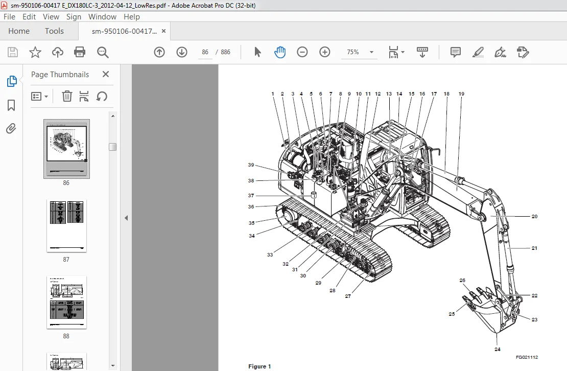
Component Locations……………………………………………………… 86
General Dimensions………………………………………………………. 88
One – Piece Boom…………………………………………………….. 88
Two – Piece Boom…………………………………………………….. 89
Working Range…………………………………………………………… 90
One – Piece Boom…………………………………………………….. 90
Two – Piece Boom…………………………………………………….. 92
General Specifications…………………………………………………… 94
Engine Performance Curves (Per KS-R1004 Standard)…………………………… 96
Approximate Weight of Workload Materials…………………………………… 98
Performance Tests………………………………………………………..100
Excavator Performance Measurements…………………………………………101
Test Conditions………………………………………………………101
Travel Speed and Travel Motor Balance (Steering Deviation) Tests…………..101
Swing Speed and Deceleration Force Test…………………………………103
Cylinder Performance Tests…………………………………………….105
General Maintenance……………………………………………………………..107
General Maintenance Instructions SP002454………………………………………109
Safety Instructions………………………………………………………113
Applicable Models………………………………………………………..113
Welding Precautions and Instructions……………………………………….114
Hydraulic System – General Precautions……………………………………..115
Maintenance Service and Repair Procedure……………………………………117
General Precautions…………………………………………………..117
Hydraulic System Cleanliness and Oil Leaks………………………………….118
Maintenance Precautions for Hydraulic System Service……………………..118
Oil Leakage Precautions……………………………………………….119
Cleaning and Inspection…………………………………………………..120
General Instructions………………………………………………….120
Bearing Inspection……………………………………………………121
Standard Torques SP002404…………………………………………………….129
Safety Instructions………………………………………………………133
Applicable Models………………………………………………………..133
Torque Values for Standard Metric Fasteners…………………………………134
Torque Values for Standard U.S. Fasteners…………………………………..135
Type 8 Phosphate Coated Hardware…………………………………………..137
Torque Values for Hose Clamps……………………………………………..138
ORFS Swivel Nut Recommended Torque…………………………………………138
Torque Values for Split Flanges……………………………………………139
Torque Wrench Extension Tools……………………………………………..140
Torque Multiplication…………………………………………………140
Other Uses for Torque Wrench Extension Tools…………………………….141
Tightening Torque Specifications (Metric)……………………………….142
Upper Structure…………………………………………………………………145
Cabin SP002324………………………………………………………………147
Safety Instructions………………………………………………………151
Applicable Models………………………………………………………..151
Cabin Identification……………………………………………………..152
Rollover Protective Structure (ROPS)……………………………………152
Removal…………………………………………………………………154
Installation…………………………………………………………….158
Counterweight SP002522……………………………………………………….161
Safety Instructions………………………………………………………165
Applicable Models………………………………………………………..165
General…………………………………………………………………166
Warning for Counterweight and Front Attachment Removal……………………166
Removal…………………………………………………………………168
Installation…………………………………………………………….169
Fuel Tank SP002523…………………………………………………………..171
Safety Instructions………………………………………………………175
Applicable Models………………………………………………………..175
General Description………………………………………………………176
Parts List…………………………………………………………..176
Specifications……………………………………………………….177
Removal…………………………………………………………………178
Installation…………………………………………………………….182
Start-up Procedures………………………………………………………185
Fuel Transfer Pump (Option) SP002537…………………………………………..187
Safety Instructions………………………………………………………191
Applicable Models………………………………………………………..191
General Description………………………………………………………192
Theory of Operation…………………………………………………..192
Troubleshooting………………………………………………………….194
Replacement of Rotor and Vane……………………………………………..194
Replacement of Rear Cover…………………………………………………195
Replacement of Armature…………………………………………………..195
Swing Bearing SP002329……………………………………………………….197
Safety Instructions………………………………………………………201
Applicable Models………………………………………………………..201
Swing Bearing Maintenance…………………………………………………202
Operating Recommendation………………………………………………202
Measuring Swing Bearing Axial Play……………………………………..202
Measuring Bearing Lateral Play…………………………………………202
Swing Bearing Basic Operation………………………………………….203
Disassembly………………………………………………………….203
Assembly…………………………………………………………….205
Lower Structure and Chassis………………………………………………………207
Track Assembly SP002524………………………………………………………209
Safety Instructions………………………………………………………213
Applicable Models………………………………………………………..213
General Description………………………………………………………214
Track Tension……………………………………………………………215
Cleaning and Inspection (Wear Limits and Tolerances)…………………………217
Track Shoe…………………………………………………………..218
Lower Roller…………………………………………………………220
Upper Roller…………………………………………………………221
Front Idler………………………………………………………….222
Track Shoes and Links…………………………………………………….223
Track Removal………………………………………………………..223
Track Installation……………………………………………………224
Front Idler Roller……………………………………………………….225
Parts List…………………………………………………………..225
Front Idler Roller Disassembly…………………………………………226
Front Idler Roller Reassembly………………………………………….227
Lower Roller…………………………………………………………….230
Parts List…………………………………………………………..230
Lower Roller Removal………………………………………………….231
Lower Roller Disassembly………………………………………………231
Lower Roller Reassembly……………………………………………….232
Lower Roller Installation……………………………………………..233
Upper Roller…………………………………………………………….234
Parts List…………………………………………………………..234
Upper Roller Removal………………………………………………….235
Upper Roller Disassembly………………………………………………235
Upper Roller Reassembly……………………………………………….237
Track Spring and Track Adjusting Cylinder…………………………………..238
Parts List…………………………………………………………..238
Engine and Drivetrain……………………………………………………………241
Engine Coolant Heater (Option) SP002328………………………………………..243
Safety Instructions………………………………………………………247
Applicable Models………………………………………………………..247
Disassembly and Assembly………………………………………………….248
Changing the Circulating Pump………………………………………….248
Changing the Temperature Limiter……………………………………….250
Changing the Temperature Sensor………………………………………..251
Changing the Combustion Air Fan………………………………………..253
Changing the Burner, Flame Monitor and Glow Plug…………………………255
Changing the Burner Head………………………………………………257
Changing the Heat Exchanger……………………………………………259
Drive Coupling (Main Pump) SP002525……………………………………………261
Safety Instructions………………………………………………………265
Applicable Models………………………………………………………..265
Drive Coupling…………………………………………………………..266
Special Tools……………………………………………………………267
Pump Tool……………………………………………………………267
Installation of Drive Coupling…………………………………………….268
Installation Procedure………………………………………………..270
Hydraulics……………………………………………………………………..271
Hydraulic System Troubleshooting, Testing and Adjustment SP002608…………………273
Safety Instructions………………………………………………………277
Applicable Models………………………………………………………..277
Hydraulic System – General Notes…………………………………………..278
Hydraulic Schematic………………………………………………………279
General Notes………………………………………………………..279
Operation of Working Components……………………………………………281
Boom Operating Circuit………………………………………………..281
Boom Up Circuit………………………………………………………281
Boom Down Circuit…………………………………………………….281
Arm Operating Circuit…………………………………………………282
Arm Crowd Circuit…………………………………………………….282
Arm Dump Circuit……………………………………………………..282
Bucket Operating Circuit………………………………………………283
Bucket Crowd Circuit………………………………………………….283
Bucket Dump Circuit…………………………………………………..283
Swing Operating Circuit……………………………………………….283
Right Swing Operating Circuit………………………………………….284
Left Swing Operating Circuit…………………………………………..284
Swing Relief Valve and Makeup Valve…………………………………….284
Travel Operating Circuit………………………………………………284
Forward Travel Circuit………………………………………………..285
Reverse Travel Circuit………………………………………………..285
Procedural Troubleshooting Baseline Recommendations………………………….286
Initial Checks and Tests to Establish Operating Condition of the Excavator….286
Pilot Pressure…………………………………………………………..288
Adjustment and Testing………………………………………………..288
Power Mode Valve…………………………………………………………289
Current Signal and Hydraulic Pressure Adjustments………………………..289
Pressure Up Valve………………………………………………………..290
Checks and Adjustments………………………………………………..290
Pump Input Power Control………………………………………………….292
Pump Regulator Adjustment……………………………………………..292
Flow Meter and Flow Meter Kit Installation and Testing……………………….295
Swing System Troubleshooting………………………………………………297
Precautions/Initial Checks…………………………………………….297
Swing Relief Valve Checking and Adjustment………………………………298
Troubleshooting – Swing Gearbox……………………………………………300
Troubleshooting – Hydraulic Problems……………………………………….301
Troubleshooting – Control Valve……………………………………………303
Troubleshooting – Travel Control Valve……………………………………..304
Troubleshooting – Joystick Control Valve……………………………………305
Accumulator SP002455…………………………………………………………307
Safety Instructions………………………………………………………311
Applicable Models………………………………………………………..311
General Description………………………………………………………312
Specifications……………………………………………………….314
Center Joint (Swivel) SP002456………………………………………………..315
Safety Instructions………………………………………………………319
Applicable Models………………………………………………………..319
General Description………………………………………………………321
Parts List…………………………………………………………..322
Troubleshooting, Testing and Adjustment…………………………………….323
Inspection…………………………………………………………..323
Testing……………………………………………………………..323
Disassembly……………………………………………………………..324
Reassembly………………………………………………………………327
Cylinders SP002579…………………………………………………………..329
Safety Instructions………………………………………………………333
Applicable Models………………………………………………………..333
General Description………………………………………………………334
Theory of Operation…………………………………………………..334
Parts List…………………………………………………………..336
Special Tools and Materials……………………………………………….342
Piston Nut…………………………………………………………..342
Piston Jig…………………………………………………………..344
Steel Bushing Jig…………………………………………………….347
Dust Wiper Jig……………………………………………………….350
Slipper Seal Jig……………………………………………………..353
Slipper Seal Straightening Jig…………………………………………356
Disassembly……………………………………………………………..359
Reassembly………………………………………………………………364
Swing Device SP002498………………………………………………………..369
Safety Instructions………………………………………………………373
Applicable Models………………………………………………………..373
Indication of Type……………………………………………………….374
Specifications…………………………………………………………..375
Structure and Principle of Operation……………………………………….376
Structure……………………………………………………………376
Principles of Operation……………………………………………….381
Valve Casing…………………………………………………………382
Brake Part…………………………………………………………..385
Cautions for Operation……………………………………………………386
Inspection…………………………………………………………..386
Direction of Rotation…………………………………………………386
External Load at the End of Shaft………………………………………387
Hydraulic Oil and Temperature Range…………………………………….387
Filter………………………………………………………………388
Installation and Piping……………………………………………….388
Oil Filling and Air Breather…………………………………………..389
Instructions before Starting to Operate…………………………………389
Troubleshooting………………………………………………………….390
General Pre-caustions…………………………………………………390
Examination of Hydraulic Motor…………………………………………390
Troubleshooting………………………………………………………391
Disassembly and Reassembly………………………………………………..394
Disassemble Swing Motor……………………………………………….396
Reassemble Swing Motor………………………………………………..400
Disassemble the Reduction Gear…………………………………………405
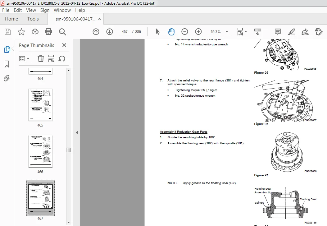
Reassemble the Reduction Gear………………………………………….409
Maintenance Instructions………………………………………………417
Travel Device SP002514……………………………………………………….419
Safety Instructions………………………………………………………423
Applicable Models………………………………………………………..423
Basic Structure and Drawings…………………………………………..425
Operation Principle…………………………………………………..430
Cautions for Operation………………………………………………..437
Troubleshooting………………………………………………………440
Disassembly………………………………………………………….446
Assembly…………………………………………………………….460
Matters to Check after Assembly………………………………………..476
Performance Test……………………………………………………..476
Main Pump SP002531…………………………………………………………..479
Safety Instructions………………………………………………………483
Applicable Models………………………………………………………..483
ectional View……………………………………………………………484
A8VO80LA1KH1/63………………………………………………………484
General Repair Guidelines…………………………………………………486
Seal Kits and Subassemblies……………………………………………….488
Sealing the Driveshaft……………………………………………………492
Gear Pump Sealing………………………………………………………..494
Remove Control Housing……………………………………………………495
Control Module…………………………………………………………..499
Control Module LR…………………………………………………….499
Control Module H……………………………………………………..500
Removing the Controller…………………………………………………..501
Valve Plate With Valves…………………………………………………..503
Remove Rotary Groups……………………………………………………..504
Remove Intermediate Wheel…………………………………………………507
Remove Auxiliary Drive……………………………………………………509
Inspection………………………………………………………………512
Assembling the Rotary Group……………………………………………….517
Pump Assembly……………………………………………………………519
Assembly Guideline……………………………………………………521
Adjustment of the Hydraulic Component of the Rotary Group…………………521
Hydraulic Component – Measurement “D”………………………………………522
Measuring Device – Hydraulic Component 452 269…………………………..522
Mounting Position…………………………………………………….523
Measuring Procedure…………………………………………………..525
Installation of Control Housing……………………………………………526
Assembly of Intermediate Wheel…………………………………………….529
Installation of Gear Pump…………………………………………………530
Installation of Cover / Auxiliary Drive…………………………………….531
Assembly Guidelines for Tightening Torques………………………………….532
Bolts (To N 08.001)…………………………………………………..532
Plugs with Internal Hexagon and Profile Seal Ring (to N 02.009)……………533
Seal-lock – Sealing Nuts (to N 02.100)………………………………….533
Gear Pump SP002500…………………………………………………………..535
Safety Instructions………………………………………………………539
Applicable Models………………………………………………………..539
Single Gear Pump…………………………………………………………540
Disassembly………………………………………………………….540
Reassembly…………………………………………………………..542
Main Control Valve SP002584…………………………………………………..547
Safety Instructions………………………………………………………551
Applicable Models………………………………………………………..551
General Description………………………………………………………553
Theory of Operation…………………………………………………..554
Composite Operation…………………………………………………..565
Antidrift Valve………………………………………………………566
Disassembly……………………………………………………………..568
Precautions for Disassembly……………………………………………568
Disassembling Procedures………………………………………………568
Washing…………………………………………………………………574
Inspection………………………………………………………………574
Assembling………………………………………………………………575
Subassembly………………………………………………………….575
Assembling Control Valve………………………………………………578
Relief Valve…………………………………………………………….584
Main Relief Valve…………………………………………………….584
Overload Relief Valve…………………………………………………588
Negacon Relief Valve………………………………………………….591
Adjusting Relief Valve………………………………………………..593
Installation…………………………………………………………….594
Operation……………………………………………………………….594
Control Valve Specification……………………………………………….595
Troubleshooting………………………………………………………….596
Control Valve: overall………………………………………………..596
Hydraulic System: Overall……………………………………………..597
Remote Control Valve (Work Lever / Joystick) SP002395……………………………599
Safety Instructions………………………………………………………603
Applicable Models………………………………………………………..603
General Description………………………………………………………605
Theory of Operation…………………………………………………..605
Parts List…………………………………………………………..606
Specifications……………………………………………………….608
Torques……………………………………………………………..608
Tools and Materials………………………………………………………608
Disassembly……………………………………………………………..609
Reassembly………………………………………………………………612
Start-up Procedures………………………………………………………620
Travel Control Valve (with Damper) SP002381…………………………………….621
Safety Instructions………………………………………………………625
Applicable Models………………………………………………………..625
General Description………………………………………………………626
Theory of Operation…………………………………………………..626
Pressure Reducing Valve……………………………………………….627
Operating Theory of Damper Mechanism……………………………………628
Causes of Faults and Measures……………………………………………..629
Parts List…………………………………………………………..630
Specification………………………………………………………..632
Torques……………………………………………………………..632
Removal…………………………………………………………………633
Disassembly……………………………………………………………..636
Cleaning and Inspection (Wear Limits and Tolerances)…………………………638
Reassembly………………………………………………………………639
Installation…………………………………………………………….644
Start-up Procedures………………………………………………………647
Solenoid Valve Assembly SP002406………………………………………………649
Safety Instructions………………………………………………………653
Applicable Models………………………………………………………..653
5-Solenoid Valve…………………………………………………………654
Parts List…………………………………………………………..654
Functions of 5-Solenoid Valve Assembly………………………………….655
Assembly Diagram and Tools Required…………………………………….656
Cautions During Disassembly and Reassembly………………………………657
Solenoid Valve Diagram………………………………………………..658
Check Points and Solutions for Problems…………………………………659
Breaker EPPR Valve (Option) SP002458…………………………………………..661
Safety Instructions………………………………………………………665
Applicable Models………………………………………………………..665
Structure……………………………………………………………….666
Parts List…………………………………………………………..666
Functions and Operation…………………………………………………..667
Cautions for Operation……………………………………………………667
Maintenance Instructions………………………………………………….668
Maintenance………………………………………………………….668
Disassembly………………………………………………………….669
Assembly…………………………………………………………….670
Dozer Valve SP002529…………………………………………………………673
Safety Instructions………………………………………………………677
Applicable Models………………………………………………………..677
Structure Diagram………………………………………………………..678
Performance Specification…………………………………………………679
Hydraulic Pressure Circuit Diagram…………………………………………679
Parts List………………………………………………………………680
Disassembly and Assembly Tools…………………………………………….681
Disassembly……………………………………………………………..681
Assembly Method………………………………………………………….683
Hydraulic Schematic (DX180LC-3) SP002532……………………………………….687
Safety Instructions………………………………………………………691
Applicable Models………………………………………………………..691
DX180LC-3……………………………………………………………….693
Electrical System……………………………………………………………….695
Electrical System SP002337……………………………………………………697
Safety Instructions………………………………………………………703
Applicable Models………………………………………………………..703
Introduction…………………………………………………………….705
Electrical Supply System………………………………………………….706
Engine Starting Circuit…………………………………………………..708
Start Operation………………………………………………………708
After Start………………………………………………………….710
Engine Preheating System………………………………………………….712
Engine Stop……………………………………………………………..714
Charging System………………………………………………………….716
Monitoring System………………………………………………………..717
Instrument Panel……………………………………………………..718
Functional Check……………………………………………………..718
Monitoring System Schematic……………………………………………720
Operation……………………………………………………………….722
Instruments………………………………………………………….722
Warning and Indicator Lights………………………………………………724
Indication of Warning Lights…………………………………………..724
Indication of Multifunction Gauge………………………………………726
Initial Operation………………………………………………………..727
Graphic Information Area Display…………………………………………..728
Overview…………………………………………………………….728
Main Menus for the Graphic Display Area…………………………………728
Menu Selector Buttons…………………………………………………728
User Menu……………………………………………………………….729
User Menu – Access and Escape Methods…………………………………..729
Special Menu…………………………………………………………….761
Entering/Accessing and Exiting/Escaping Menus……………………………761
Special Menu Selections……………………………………………….762
Electronic Hydraulic Control System (EPOS)………………………………….788
Control System Schematic………………………………………………788
Power Plus Mode Control…………………………………………………..790
Operation……………………………………………………………792
Power Mode Control – Circuit Diagram……………………………………….794
Engine Control System…………………………………………………….796
Engine Control Dial………………………………………………………797
Engine Control Circuit Diagram…………………………………………….798
Automatic Deceleration Control (Auto Idle Control)…………………………..800
Engine Overheat Protection System………………………………………….802
Power Boost Mode…………………………………………………………804
Operation……………………………………………………………804
Power Boost Control – Circuit Diagram…………………………………..806
Automatic Travel Speed Control…………………………………………….808
Automatic Travel Speed Control – Circuit Diagram…………………………810
Self-diagnostic Function………………………………………………….811
EPOS Controller………………………………………………………811
Air Conditioner System……………………………………………………813
Outline……………………………………………………………..813
Internal and External Filters………………………………………….814
Air-Conditioning System Layout…………………………………………816
Air Conditioner/heater Circuit Diagram………………………………….817
Air Conditioner/heater Unit……………………………………………818
Ambient Air Temperature Sensor…………………………………………823
Sun Sensor…………………………………………………………..824
Control Panel………………………………………………………..824
Compressor…………………………………………………………..832
Receiver Dryer……………………………………………………….832
Troubleshooting………………………………………………………….833
Weight of R134a Gas Used In Machines……………………………………….835
Refrigerant System Repairs………………………………………………..836
Refrigerant Safe Handling Procedures……………………………………836
Repair and Replacement Procedure……………………………………….837
Refrigerant Recovery………………………………………………….839
Vacuuming Refrigerant System…………………………………………..839
Leakage Check………………………………………………………..841
Refrigerant Charging………………………………………………….841
Inspecting System For Leakage………………………………………….843
Wiper System…………………………………………………………….844
Wiper Circuit………………………………………………………..844
Wiper operation………………………………………………………845
Lighting System………………………………………………………….848
Lighting System Circuit Diagram………………………………………..848
Kind of Light………………………………………………………..849
Operation……………………………………………………………849
Overload Warning Device…………………………………………………..850
Overload Warning Device Circuit Diagram…………………………………850
Audio Controller…………………………………………………………851
Audio Controller Circuit Diagram……………………………………….851
Electrical Schematic SP002508…………………………………………………853
Safety Instructions………………………………………………………857
Applicable Models………………………………………………………..857
DX140LC-3/DX180LC-3/DX225LC-3/DX255LC-3…………………………………….859
Attachments…………………………………………………………………….861
Boom and Arm SP002533………………………………………………………..863
Safety Instructions………………………………………………………867
Applicable Models………………………………………………………..867
Front Attachment Pin Specifications………………………………………..868
DX180LC-3……………………………………………………………869
Front Attachment – Removal and Installation…………………………………870
Arm Removal Procedure…………………………………………………870
Boom Removal Procedure………………………………………………..872
Installation…………………………………………………………….873
Arm Installation Procedure…………………………………………….873
Boom Installation Procedure……………………………………………873
Start-up Procedures………………………………………………………874
Bucket SP002506……………………………………………………………..875
Safety Instructions………………………………………………………879
Applicable Models………………………………………………………..879
Bucket Tooth Inspection and Replacement…………………………………….880
Bucket O-ring Replacement…………………………………………………881
Attachments……………………………………………………………..883
Bucket Replacement and Reversal………………………………………..883
Replacement………………………………………………………….884
Reversal…………………………………………………………….885
DOOSAN DX180LC-3 EXCAVATOR SHOP MANUAL 950106-00417E – PDF DOWNLOAD:
IMAGES PREVIEW OF THE MANUAL:
PLEASE NOTE:
- This is the same manual used by the dealers to diagnose and troubleshoot your vehicle
- You will be directed to the download page as soon as the purchase is completed. The whole payment and downloading process will take anywhere between 2-5 minutes
- Need any other service / repair / parts manual, please feel free to contact [email protected] . We still have 50,000 manuals unlisted