Trusted Business
Verified & Licensed
Virus Free Files
100% Safe Downloads
Secure Payment
SSL Protected
Instant Delivery
Available Immediately
Sale!


Doosan DX420LC-3 Excavator Shop Manual 950106-00398E – PDF DOWNLOAD
Original price was: $65.95.$31.95Current price is: $31.95.
Doosan DX420LC-3 Excavator Shop Manual 950106-00398E – PDF DOWNLOAD
Serial Number 1001 and Up
950106-00398E
Instant PDF Download
Available immediately
Save to Your Device
Download & keep forever
Antivirus Scanned
100% virus-free
Trusted Worldwide
175,000+ customers
Description
Doosan DX420LC-3 Excavator Shop Manual 950106-00398E – PDF DOWNLOAD
DESCRIPTION:
Doosan DX420LC-3 Excavator Shop Manual 950106-00398E – PDF DOWNLOAD
Serial Number 1001 and Up
950106-00398E
GENERAL:
Safe Operation is Operator’s Responsibility:
- Only trained and authorized personnel should operate and maintain the machine. Follow all safety rules, regulations and instructions when operating or performing maintenance on machine.
- Do not operate machine if you are under the influence of drugs or alcohol. An operator who is taking prescription drugs must get medical advice to determine if he or she can safely operate a machine. When working with other personnel on a work site, be sure that all personnel know nature of work and understand all hand signals that are to be used.
- Be sure that all guards and shields are installed in their proper location. Have guards and shields repaired or replaced immediately if damaged.
- Be sure that you understand the use and maintenance of all safety features such as safety lock lever and seat belt. Use them properly. Never remove, modify or disable any safety features. Always keep them in good operating condition. Always check for and know the location of underground and overhead utility lines before excavating.
- Failure to use and maintain safety features according to instructions in this manual, Safety Manual and Shop Manual can result in death or serious injury. Know Your Machine Know how to operate your machine. Know the purpose of all controls, gauges, signals, indicators and monitor displays.
- Know the rated load capacity, speed range, braking and steering characteristics, turning radius and operating clearances. Keep in mind that rain, snow, ice, loose gravel, soft ground, slopes etc., can change operating capabilities of your machine.
- Proper Work Tools and Attachments Only use work tools and attachments that are recommended by DOOSAN for use on DOOSAN machines. When installing and using optional attachments, read instruction manual for attachment, and general information related to attachments in this manual.
- Because DOOSAN cannot anticipate, identify or test all attachments that owners may want to install on their machines, contact DOOSAN for written authorization and
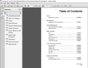
TABLE OF CONTENTS:
Doosan DX420LC-3 Excavator Shop Manual 950106-00398E – PDF DOWNLOAD
DX420LC-3.....................................................................................................   0
	Table of Contents.........................................................................................   7
	Safety....................................................................................................   9
		Track Excavator Maintenance Safety SP002322...........................................................  11
			Safety Instructions...............................................................................  15
			Applicable Models.................................................................................  15
			Safety Messages...................................................................................  16
				Signal Words..................................................................................  16
				Other Signal Words............................................................................  17
			Safety Decals.....................................................................................  17
			General...........................................................................................  18
				Safe Operation is Operator's Responsibility...................................................  18
				Know Your Machine.............................................................................  18
				Proper Work Tools and Attachments.............................................................  18
				Pressurized Fluids............................................................................  19
				Flying or Falling Objects.....................................................................  20
				Personal Protective Equipment (PPE)...........................................................  20
				Correction of Machine Problems................................................................  20
				Crushing and Cutting..........................................................................  21
				Hot Coolant and Oils - Burn Prevention........................................................  22
				Fire and Explosion Prevention.................................................................  22
				Fire Extinguisher and First-Aid Kit (Emergency Medical Kit)...................................  26
				Electrical System and Electrical Shock........................................................  26
				Rollover Protective Structure (ROPS)..........................................................  27
			Transportation....................................................................................  30
				Obey State and Local Over-the-Road Regulations................................................  30
				Loading and Unloading.........................................................................  30
				Transporting Machine..........................................................................  31
			Operation.........................................................................................  32
				Before Engine Starting........................................................................  32
				Work Site.....................................................................................  33
				Mounting/Dismounting..........................................................................  34
				Cleaning......................................................................................  35
				Operator Station..............................................................................  35
				Seat Belt.....................................................................................  36
				Visibility Information........................................................................  37
				Boost Starting or Charging Engine Batteries...................................................  38
				Starting Engine...............................................................................  39
				Swinging or Traveling.........................................................................  40
				Lifting and Digging...........................................................................  42
				Operation on Slopes...........................................................................  43
				Towing........................................................................................  44
				Attachment....................................................................................  45
				Equipment Lowering with Engine Stopped........................................................  45
				Engine Stop...................................................................................  45
				Parking Machine...............................................................................  46
				Preservation/Storing Machine..................................................................  47
			Maintenance.......................................................................................  49
				Warning Tag...................................................................................  52
				Cleaning......................................................................................  53
				Proper Tools and Clothing.....................................................................  53
				Disassembling Precautions.....................................................................  53
				Use of Lighting...............................................................................  54
				Fire and Explosion Prevention.................................................................  54
				Burn Prevention...............................................................................  55
				Rubber That Contains Fluorides................................................................  56
				Rubber and Plastics...........................................................................  57
				Welding Repairs...............................................................................  58
				Warning for Counterweight and Front Attachment Removal........................................  59
				Lock Inspection Covers........................................................................  60
				Working on Machine............................................................................  60
				Accumulator...................................................................................  61
				Compressed Air................................................................................  61
				Track Tension Adjustments.....................................................................  62
				Supports and Blocking for Work Equipment......................................................  62
				High-pressure Lines, Tubes and Hoses..........................................................  63
				Battery.......................................................................................  64
			Environment and Circumstances.....................................................................  66
				Work Site Areas Requiring Extra Caution.......................................................  66
				High-voltage Cables...........................................................................  68
				Underground Operation.........................................................................  69
				Working in Water..............................................................................  69
				Working in Contaminated Environment...........................................................  69
				Operation in Extreme Conditions...............................................................  70
				Exhaust Ventilation...........................................................................  74
				Asbestos Information..........................................................................  74
				Silica Dust Information.......................................................................  75
				Disposal of Hazardous Materials...............................................................  75
				Sound.........................................................................................  76
				Vibration.....................................................................................  76
	Specifications............................................................................................  77
		Specification for DX420LC-3 SP002670..................................................................  79
			Safety Instructions...............................................................................  83
			Applicable Models.................................................................................  83
			General Description...............................................................................  85
			Component Locations...............................................................................  86
			Overall Dimensions................................................................................  88
			Working Range.....................................................................................  90
			General Specifications............................................................................  92
			Engine Performance Curves (Per KS-R1004 Standard).................................................  94
			Approximate Weight of Workload Materials..........................................................  96
			Performance Tests.................................................................................  98
			Excavator Performance Measurements................................................................  99
				Test Conditions...............................................................................  99
				Travel Speed and Travel Motor Balance (Steering Deviation) Tests..............................  99
					Speed Test................................................................................  99
					Travel Deviation.......................................................................... 101
				Swing Speed and Deceleration Force Test....................................................... 101
					Swing Speed Test.......................................................................... 101
					Swing Deceleration Force Test............................................................. 102
				Cylinder Performance Tests.................................................................... 103
					Boom Cylinders Test....................................................................... 103
					Arm Cylinder Test......................................................................... 103
					Bucket Cylinder Test...................................................................... 103
					Hydraulic Cylinder Natural Drop Test...................................................... 103
					Travel Motor Jack-up Test................................................................. 103
	General Maintenance....................................................................................... 105
		General Maintenance Instructions SP002454............................................................. 107
			Safety Instructions............................................................................... 111
			Applicable Models................................................................................. 111
			Welding Precautions and Instructions.............................................................. 112
			Hydraulic System - General Precautions............................................................ 113
			Maintenance Service and Repair Procedure.......................................................... 115
				General Precautions........................................................................... 115
			Hydraulic System Cleanliness and Oil Leaks........................................................ 116
				Maintenance Precautions for Hydraulic System Service.......................................... 116
				Oil Leakage Precautions....................................................................... 117
			Cleaning and Inspection........................................................................... 118
				General Instructions.......................................................................... 118
				Bearing Inspection............................................................................ 119
		Standard Torques SP002404............................................................................. 127
			Safety Instructions............................................................................... 131
			Applicable Models................................................................................. 131
			Torque Values for Standard Metric Fasteners....................................................... 132
			Torque Values for Standard U.S. Fasteners......................................................... 133
			Type 8 Phosphate Coated Hardware.................................................................. 135
			Torque Values for Hose Clamps..................................................................... 136
			ORFS Swivel Nut Recommended Torque................................................................ 136
			Torque Values for Split Flanges................................................................... 137
			Torque Wrench Extension Tools..................................................................... 138
				Torque Multiplication......................................................................... 138
				Other Uses for Torque Wrench Extension Tools.................................................. 139
				Tightening Torque Specifications (Metric)..................................................... 140
	Upper Structure........................................................................................... 143
		Cabin SP002324........................................................................................ 145
			Safety Instructions............................................................................... 149
			Applicable Models................................................................................. 149
			Cabin Identification.............................................................................. 150
				Rollover Protective Structure (ROPS).......................................................... 150
			Removal........................................................................................... 152
			Installation...................................................................................... 156
		Counterweight SP002697................................................................................ 159
			Safety Instructions............................................................................... 163
			Applicable Models................................................................................. 163
			General........................................................................................... 164
				Warning for Counterweight and Front Attachment Removal........................................ 164
			Removal........................................................................................... 166
			Installation...................................................................................... 167
		Fuel Tank SP002699.................................................................................... 169
			Safety Instructions............................................................................... 173
			Applicable Models................................................................................. 173
			General Description............................................................................... 174
				Parts List.................................................................................... 174
				Specifications................................................................................ 175
			Removal........................................................................................... 176
			Installation...................................................................................... 180
			Start-up Procedures............................................................................... 183
		Fuel Transfer Pump (Option) SP002560.................................................................. 185
			Safety Instructions............................................................................... 189
			Applicable Models................................................................................. 189
			General Description............................................................................... 190
				Theory of Operation........................................................................... 190
			Troubleshooting................................................................................... 192
			Replacement of Rotor and Vane..................................................................... 192
			Replacement of Rear Cover......................................................................... 193
			Replacement of Armature........................................................................... 193
		Swing Bearing SP002329................................................................................ 195
			Safety Instructions............................................................................... 199
			Applicable Models................................................................................. 199
			Swing Bearing Maintenance......................................................................... 200
				Operating Recommendation...................................................................... 200
				Measuring Swing Bearing Axial Play............................................................ 200
				Measuring Bearing Lateral Play................................................................ 200
				Swing Bearing Basic Operation................................................................. 201
				Disassembly................................................................................... 201
				Assembly...................................................................................... 203
	Lower Structure and Chassis............................................................................... 205
		Track Assembly SP002561............................................................................... 207
			Safety Instructions............................................................................... 211
			Applicable Models................................................................................. 211
			General Description............................................................................... 212
			Track Tension..................................................................................... 213
			Cleaning and Inspection (Wear Limits and Tolerances).............................................. 215
				Track Shoe.................................................................................... 216
				Lower Roller.................................................................................. 218
				Upper Roller.................................................................................. 219
				Front Idler................................................................................... 220
			Track Shoes and Links............................................................................. 221
				Track Removal................................................................................. 221
				Track Installation............................................................................ 222
			Front Idler Roller................................................................................ 224
				Parts List.................................................................................... 224
				Front Idler Roller Disassembly................................................................ 225
				Front Idler Roller Reassembly................................................................. 227
			Lower Roller...................................................................................... 228
				Parts List.................................................................................... 228
				Lower Roller Removal.......................................................................... 229
				Lower Roller Disassembly...................................................................... 229
				Lower Roller Reassembly....................................................................... 230
				Lower Roller Installation..................................................................... 231
			Upper Roller...................................................................................... 232
				Parts List.................................................................................... 232
				Upper Roller Removal.......................................................................... 233
				Upper Roller Disassembly...................................................................... 233
				Upper Roller Reassembly....................................................................... 235
			Track Spring and Track Adjusting Cylinder......................................................... 236
				Parts List.................................................................................... 236
	Engine and Drivetrain..................................................................................... 239
		Engine SP002654....................................................................................... 241
			Safety Instructions............................................................................... 245
			Applicable Models................................................................................. 245
			Introduction...................................................................................... 246
				Safety Information............................................................................ 246
			Service Information Guide......................................................................... 247
				Contents Included in Service Information...................................................... 247
				Plastic Gauge................................................................................. 250
				Recommended Liquid Gasket..................................................................... 251
				Thread Locking Adhesive Agent................................................................. 254
				Term.......................................................................................... 255
				Abbreviations................................................................................. 256
				Standard Bolts................................................................................ 259
			Maintenance Information........................................................................... 264
				Maintenance Precautions....................................................................... 264
				Primary Specifications........................................................................ 269
				Function, Structure, Operation................................................................ 272
				Introduction to the Trouble Diagnosis......................................................... 329
			Functional Inspection............................................................................. 343
				Engine Compression Pressure Inspection........................................................ 343
				Fuel System Check............................................................................. 345
				Air Intake System Check....................................................................... 346
				Exhaust System Check.......................................................................... 346
				DPD Control System Check...................................................................... 347
				EGR Control System Check...................................................................... 350
				Starting System Check......................................................................... 351
				Glow Control System Check..................................................................... 353
				OBD System Check.............................................................................. 354
				Inspection of the Diagnostic Light Warning Light Illumination Circuit System.................. 357
				Inspection of the Diagnostic Light Warning Light Blinking Circuit System...................... 357
				Inspection of the Starter Circuit System...................................................... 359
			Symptom........................................................................................... 361
				Engine Start Failure.......................................................................... 361
				Engine stalling............................................................................... 363
				Engine Hunching, Rough Idling................................................................. 366
				Excessive White Smoke in the Exhaust Gas...................................................... 367
				Excessive Black Smoke in the Exhaust Gas...................................................... 369
				Abnormal Noise................................................................................ 370
				Large Fuel Consumption........................................................................ 371
				Large Oil Consumption......................................................................... 374
				Insufficient Engine Output.................................................................... 375
				DPD System Manual Regeneration Frequently..................................................... 377
				DPD System Regeneration Long Time............................................................. 380
			DTC Information................................................................................... 382
				DTC P0016 (Flash Code 16) Crankshaft Position - Camshaft Position Correlation................. 382
				DTC P0045 (Flash Code 33) Turbocharger Boost Control Solenoid Circuit......................... 382
				DTC P0087 (Flash Code 225) Fuel Rail/ System Pressure - Too Low............................... 383
				DTC P0088 (Flash Code 118) Fuel Rail/ System Pressure - Too High.............................. 384
				DTC P0089 (Flash Code 151) Fuel Pressure Regulator Performance................................ 385
				DTC P0091 (Flash Code 247) Fuel Pressure Regulator Control Circuit Low........................ 386
				DTC P0093 (Flash Code 227) Fuel System Leak Detected.......................................... 386
				DTC P0102 (Flash Code 91) Mass Airflow Circuit Low Input...................................... 387
				DTC P0103 (Flash Code 91) Mass Airflow Circuit High Input..................................... 388
				DTC P0112 (Flash Code 22) Intake Air Temperature Sensor Circuit Low........................... 389
				DTC P0113 (Flash Code 22) Intake Air Temperature Sensor Circuit High.......................... 390
				DTC P0117 (Flash Code 23) Engine Coolant Temperature Sensor Circuit Low....................... 390
				DTC P0118 (Flash Code 23) Engine Coolant Temperature Sensor Circuit High...................... 391
				DTC P0122 (Flash Code 43) Throttle Position Sensor Circuit Low................................ 392
				DTC P0123 (Flash Code 43) Throttle Position Sensor Circuit High............................... 393
				DTC P0182 (Flash Code 211) Fuel Temperature Sensor Circuit Low................................ 394
				DTC P0183 (Flash Code 211) Fuel Temperature Sensor Circuit High............................... 394
				DTC P0192 (Flash Code 245) Fuel Rail Pressure Sensor Circuit Low.............................. 395
				DTC P0193 (Flash Code 245) Fuel Rail Pressure Sensor Circuit High............................. 397
				DTC P0201 (Flash Code 271) Injector Circuit - Cylinder 1...................................... 398
				DTC P0202 (Flash Code 272) Injector Circuit - Cylinder 2...................................... 398
				DTC P0203 (Flash Code 273) Injector Circuit - Cylinder 3...................................... 399
				DTC P0204 (Flash Code 274) Injector Circuit - Cylinder 4...................................... 400
				DTC P0205 (Flash Code 275) Injector Circuit - Cylinder 5...................................... 401
				DTC P0206 (Flash Code 276) Injector Circuit - Cylinder 6...................................... 401
				DTC P0217 (Flash Code 542) Engine Coolant Over Temperature Condition.......................... 402
				DTC P0219 (Flash Code 543) Engine Overspeed Condition......................................... 403
				DTC P0234 (Flash Code 42) Turbocharger Overboost Condition.................................... 403
				DTC P0237 (Flash Code 32) Turbo Charger Boost Sensor Circuit Low.............................. 404
				DTC P0238 (Flash Code 32) Turbo Charger Boost Sensor Circuit High............................. 405
				DTC P0335 (Flash Code 15) Crankshaft Position Sensor Circuit.................................. 405
				DTC P0336 (Flash Code 15) Crankshaft Position Sensor Circuit Range/ Performance............... 406
				DTC P0340 (Flash Code 14) Camshaft Position Sensor Circuit.................................... 407
				DTC P0341 (Flash Code 14) Camshaft Position Sensor Circuit Range/ Performance................. 408
				DTC P0404 (Flash Code 45) Exhaust Gas Recirculation 1 Control Circuit Range/ Performance...... 408
				DTC P0409 (Flash Code 44) Exhaust Gas Recirculation 1 Sensor Circuit.......................... 409
				DTC P041C (Flash Code 27) Intake Manifold Temperature Sensor Circuit High..................... 410
				DTC P041D (Flash Code 27) Intake Manifold Temperature Sensor Circuit Low...................... 411
				DTC P0426 (Flash Code 143) Catalyst Temperature Sensor Circuit Range/ Performance Sensor 1.... 411
				DTC P0427 (Flash Code 48) Catalyst Temperature Sensor Circuit Low Sensor 1.................... 412
				DTC P0428 (Flash Code 48) Catalyst Temperature Sensor Circuit High Sensor 1................... 413
				DTC P042B (Flash Code 145) Catalyst Temperature Sensor Circuit Range/ Performance Sensor 2.... 414
				DTC P042C (Flash Code 49) Catalyst Temperature Sensor Circuit Low Sensor 2.................... 415
				DTC P042D (Flash Code 49) Catalyst Temperature Sensor Circuit High Sensor 2................... 416
				DTC P0522 (Flash Code 295) Oil Pressure Sensor Circuit Low.................................... 417
				DTC P0523 (Flash Code 295) Oil Pressure Sensor Circuit High................................... 417
				DTC P0560 (Flash Code 155) System Voltage..................................................... 418
				DTC P0563 (Flash Code 35) System Voltage High................................................. 419
				DTC P0601 (Flash Code 53) Internal Control Module Memory Check Sum Error...................... 419
				DTC P0602 (Flash Code 154) Control Module Programming Error................................... 420
				DTC P0604 (Flash Code 153) Internal Control Module Random Access Memory (Ram) Error........... 420
				DTC P0606 (Flash Code 51) ECM/PCM Processor................................................... 421
				DTC P060B (Flash Code 36) Internal Control Module A/D Processing Performance.................. 421
				DTC P0638 (Flash Code 61) Throttle Actuator Control Range/Performance......................... 422
				DTC P0641 (Flash Code 55) Sensor Reference Voltage 1 Circuit.................................. 422
				DTC P0650 (Flash Code 77) Malfunction Indicator Light (MIL) Control Circuit................... 423
				DTC P0651 (Flash Code 56) Sensor Reference Voltage 2 Circuit.................................. 424
				DTC P0685 (Flash Code 416) ECM/PCM Power Relay Control Circuit/Open........................... 425
				DTC P0687 (Flash Code 416) ECM/PCM Power Relay Control Circuit High........................... 425
				DTC P0697 (Flash Code 57) Sensor Reference Voltage 3 Circuit.................................. 426
				DTC P1062 (Flash Code 257) Fuel Pressure Regulator 1 Solenoid Control Circuit................. 427
				DTC P1063 (Flash Code 258) Fuel Pressure Regulator 2 Solenoid Control Circuit................. 427
				DTC P1093 (Flash Code 226) Fuel Rail Pressure (FRP) Too Low................................... 428
				DTC P1112 (Flash Code 295) Boost Temperature Sensor Circuit Low............................... 429
				DTC P1113 (Flash Code 295) Boost Temperature Sensor Circuit High.............................. 429
				DTC P1261 (Flash Code 34) Injector Positive Voltage Control Circuit Group1.................... 430
				DTC P1262 (Flash Code 34) Injector Positive Voltage Control Circuit Group2.................... 431
				DTC P1293 (Flash Code 221) Fuel Filter Pressure Sensor Circuit Low............................ 431
				DTC P1294 (Flash Code 221) Fuel Filter Pressure Sensor Circuit High........................... 432
				DTC P1404 (Flash Code 45) Exhaust Gas Recirculation 1 Closed Position Performance............. 433
				DTC P140A (Flash Code 345) Exhaust Gas Recirculation 2 Control Circuit Range/ Performance..... 433
				DTC P140B (Flash Code 344) Exhaust Gas Recirculation 2 Sensor Circuit......................... 434
				DTC P140C (Flash Code 345) Exhaust Gas Recirculation 2 Closed Position Performance............ 435
				DTC P1455 (Flash Code 132) PM Over Accumulation............................................... 436
				DTC P1471 (Flash Code 149) DPD Insufficient Regeneration...................................... 437
				DTC P1621 (Flash Code 54) Control Module Long Term Memory Performance......................... 437
				DTC P1655 (Flash Code 59) Sensor Reference Voltage 4 Circuit.................................. 438
				DTC P1669 (Flash Code 75) DPD Light Control Circuit........................................... 439
				DTC P2122 (Flash Code 121) Pedal Position Sensor 1 Circuit Low Input.......................... 440
				DTC P2123 (Flash Code 121) Pedal Position Sensor 1 Circuit High Input......................... 440
				DTC P2127 (Flash Code 122) Pedal Position Sensor 2 Circuit Low Input.......................... 441
				DTC P2128 (Flash Code 122) Pedal Position Sensor 2 Circuit High Input......................... 442
				DTC P2138 (Flash Code 124) Pedal Position Sensor 1 - 2 Voltage Correlation.................... 442
				DTC P2146 (Flash Code 158) Fuel Injector Group 1 Supply Voltage Circuit....................... 443
				DTC P2149 (Flash Code 159) Fuel Injector Group 2 Supply Voltage Circuit....................... 444
				DTC P2228 (Flash Code 71) Barometric Pressure Circuit Low..................................... 445
				DTC P2229 (Flash Code 71) Barometric Pressure Circuit High.................................... 446
				DTC P2295 (Flash Code 248) Fuel Pressure Regulator 2 Solenoid Control Circuit Low............. 447
				DTC P2296 (Flash Code 218) Fuel Pressure Regulator 2 Solenoid Control Circuit High............ 448
				DTC P242F (Flash Code 131) DPD Restriction.................................................... 449
				DTC P2452 (Flash Code 142) DPD Differential Pressure Sensor Circuit........................... 449
				DTC P2453 (Flash Code 141) DPD Differential Pressure Sensor Circuit Range/Performance......... 450
				DTC P2454 (Flash Code 47) DPD Differential Pressure Sensor Circuit Low........................ 451
				DTC P2455 (Flash Code 47) DPD Differential Pressure Sensor Circuit High....................... 452
				DTC P2456 (Flash Code 47) DPD Differential Pressure Sensor Learned Position................... 453
				DTC P2458 (Flash Code 139) DPD Regeneration Duration.......................................... 453
				DTC U0001 (Flash Code 84) CAN-Bus Malfunction (ISO-CAN)....................................... 454
				DTC U0073 (Flash Code 84) CAN-Bus Malfunction (J1939)......................................... 455
				DTC U0101 (Flash Code 85) Lost Communication with TCM......................................... 455
				DTC U0110 (Flash Code 87) Lost Communication with VNT System.................................. 456
				DTC U0411 (Flash code 87) Turbo Charger Control Module Signal Malfunction..................... 456
				DTC Mapping Table............................................................................. 457
			Engine Control.................................................................................... 460
				DTC P0016 (Flash Code 16) Crankshaft Position - Camshaft Position Correlation................. 460
				DTC P0045 (Flash Code 33) Turbocharger Boost Control Solenoid Circuit......................... 461
				DTC P0087 (Flash Code 225) Fuel Rail/ System Pressure - Too Low............................... 464
				DTC P0088 (Flash Code 118) Fuel Rail/ System Pressure - Too High.............................. 468
				DTC P0089 (Flash Code 151) Fuel Pressure Regulator Performance................................ 471
				DTC P0091 (Flash Code 247) Fuel Pressure Regulator Control Circuit Low........................ 474
				DTC P0091 (Flash Code 247) Fuel Pressure Regulator Control Circuit Low........................ 476
				DTC P0092 (Flash Code 217) Fuel Pressure Regulator Control Circuit High....................... 477
				DTC P0093 (Flash Code 227) Fuel System Leak Detected.......................................... 478
				DTC P0102 (Flash Code 91) Mass Airflow Circuit Low Input...................................... 481
				DTC P0103 (Flash Code 91) Mass Airflow Circuit High Input..................................... 482
				DTC P0112 (Flash Code 22) Intake Air Temperature Sensor Circuit Low........................... 483
				DTC P0113 (Flash Code 22) Intake Air Temperature Sensor Circuit High.......................... 484
				DTC P0117 (Flash Code 23) Engine Coolant Temperature Sensor Circuit Low....................... 486
				DTC P0118 (Flash Code 23) Engine Coolant Temperature Sensor Circuit High...................... 487
				DTC P0122 (Flash Code 43) Throttle Position Sensor Circuit Low................................ 488
				DTC P0123 (Flash Code 43) Throttle Position Sensor Circuit High............................... 490
				DTC P0182 (Flash Code 211) Fuel Temperature Sensor Circuit Low................................ 491
				DTC P0183 (Flash Code 211) Fuel Temperature Sensor Circuit High............................... 492
				DTC P0192 (Flash Code 245) Fuel Rail Pressure Sensor Circuit Low.............................. 493
				DTC P0193 (Flash Code 245) Fuel Rail Pressure Sensor Circuit High............................. 495
				DTC P0201 (Flash Code 271) Injector Circuit - Cylinder 1...................................... 496
				DTC P0202 (Flash Code 272) Injector Circuit - Cylinder 2...................................... 498
				DTC P0203 (Flash Code 273) Injector Circuit - Cylinder 3...................................... 500
				DTC P0204 (Flash Code 274) Injector Circuit - Cylinder 4...................................... 502
				DTC P0205 (Flash Code 275) Injector Circuit - Cylinder 5...................................... 503
				DTC P0206 (Flash Code 276) Injector Circuit - Cylinder 6...................................... 505
				DTC P0217 (Flash Code 542) Engine Coolant Over Temperature Condition.......................... 507
				DTC P0219 (Flash Code 543) Engine Overspeed Condition......................................... 508
				DTC P0234 (Flash Code 42) Turbocharger Overboost Condition.................................... 509
				DTC P0237 (Flash Code 32) Turbo Charger Boost Sensor Circuit Low.............................. 511
				DTC P0238 (Flash Code 32) Turbo Charger Boost Sensor Circuit High............................. 512
				DTC P0335 (Flash Code 15) Crankshaft Position Sensor Circuit.................................. 513
				DTC P0336 (Flash Code 15) Crankshaft Position Sensor Circuit Range/ Performance............... 515
				DTC P0340 (Flash Code 14) Camshaft Position Sensor Circuit.................................... 516
				DTC P0341 (Flash Code 14) Camshaft Position Sensor Circuit Range/ Performance................. 518
				DTC P0404 (Flash Code 45) Exhaust Gas Recirculation 1 Control Circuit Range/ Performance...... 519
				DTC P0409 (Flash Code 44) Exhaust Gas Recirculation 1 Sensor Circuit.......................... 520
				DTC P041C (Flash Code 27) Intake Manifold Temperature Sensor Circuit High..................... 522
				DTC P041D (Flash Code 27) Intake Manifold Temperature Sensor Circuit Low...................... 523
				DTC P0426 (Flash Code 143) Catalyst Temperature Sensor Circuit Range/ Performance Sensor 1.... 524
				DTC P0427 (Flash Code 48) Catalyst Temperature Sensor Circuit Low Sensor 1.................... 525
				DTC P0428 (Flash Code 48) Catalyst Temperature Sensor Circuit High Sensor 1................... 526
				DTC P042B (Flash Code 145) Catalyst Temperature Sensor Circuit Range/ Performance Sensor 2.... 528
				DTC P042C (Flash Code 49) Catalyst Temperature Sensor Circuit Low Sensor 2.................... 529
				DTC P042D (Flash Code 49) Catalyst Temperature Sensor Circuit High Sensor 2................... 530
				DTC P0522 (Flash Code 295) Oil Pressure Sensor Circuit Low.................................... 532
				DTC P0523 (Flash Code 295) Oil Pressure Sensor Circuit High................................... 533
				DTC P0560 (Flash Code 155) System Voltage..................................................... 534
				DTC P0563 (Flash Code 35) System Voltage High................................................. 536
				DTC P0601 (Flash Code 53) Internal Control Module Memory Check Sum Error...................... 537
				DTC P0602 (Flash Code 154) Control Module Programming Error................................... 537
				DTC P0604 (Flash Code 153) Internal Control Module Random Access Memory (RAM) Error........... 538
				DTC P0606 (Flash Code 51) ECM/PCM Processor................................................... 538
				DTC P060B (Flash Code 36) Internal Control Module A/D Processing Performance.................. 539
				DTC P0638 (Flash Code 61) Throttle Actuator Control Range/Performance......................... 539
				DTC P0641 (Flash Code 55) Sensor Reference Voltage 1 Circuit.................................. 541
				DTC P0650 (Flash Code 77) Malfunction Indicator Light (MIL) Control Circuit................... 543
				DTC P0651 (Flash Code 56) Sensor Reference Voltage 2 Circuit.................................. 544
				DTC P0685 (Flash Code 416) ECM/PCM Power Relay Control Circuit/Open........................... 546
				DTC P0687 (Flash Code 416) ECM/PCM Power Relay Control Circuit High........................... 547
				DTC P0697 (Flash Code 57) Sensor Reference Voltage 3 Circuit.................................. 548
				DTC P1062 (Flash Code 257) Fuel Pressure Regulator 1 Solenoid Control Circuit................. 549
				DTC P1063 (Flash Code 258) Fuel Pressure Regulator 2 Solenoid Control Circuit................. 550
				DTC P1093 (Flash Code 226) Fuel Rail Pressure (FRP) Too Low................................... 551
				DTC P1112 (Flash Code 295) Boost Temperature Sensor Circuit Low............................... 553
				DTC P1113 (Flash Code 295) Boost Temperature Sensor Circuit High.............................. 554
				DTC P1261 (Flash Code 34) Injector Positive Voltage Control Circuit Group 1................... 555
				DTC P1262 (Flash Code 34) Injector Positive Voltage Control Circuit Group 2................... 556
				DTC P1293 (Flash Code 221) Fuel Filter Pressure Sensor Circuit Low............................ 556
				DTC P1294 (Flash Code 221) Fuel Filter Pressure Sensor Circuit High........................... 558
				DTC P1404 (Flash Code 45) Exhaust Gas Recirculation 1 Closed Position Performance............. 559
				DTC P140A (Flash Code 345) Exhaust Gas Recirculation 2 Control Circuit Range/ Performance..... 560
				DTC P140B (Flash Code 344) Exhaust Gas Recirculation 2 Sensor Circuit......................... 561
				DTC P140C (Flash Code 345) Exhaust Gas Recirculation 2 Closed Position Performance............ 563
				DTC P1455 (Flash Code 132) PM Over Accumulation............................................... 564
				DTC P1471 (Flash Code 149) DPD Insufficient Regeneration...................................... 566
				DTC P1621 (Flash Code 54) Control Module Long Term Memory Performance......................... 568
				DTC P1655 (Flash Code 59) Sensor Reference Voltage 4 Circuit.................................. 568
				DTC P1669 (Flash Code 75) DPD Light Control Circuit........................................... 570
				DTC P2122 (Flash Code 121) Pedal Position Sensor 1 Circuit Low Input.......................... 572
				DTC P2123 (Flash Code 121) Pedal Position Sensor 1 Circuit High Input......................... 573
				DTC P2127 (Flash Code 122) Pedal Position Sensor 2 Circuit Low Input.......................... 575
				DTC P2128 (Flash Code 122) Pedal Position Sensor 2 Circuit High Input......................... 576
				DTC P2138 (Flash Code 124) Pedal Position Sensor 1 - 2 Voltage Correlation.................... 577
				DTC P2146 (Flash Code 158) Fuel Injector Group 1 Supply Voltage Circuit....................... 579
				DTC P2149 (Flash Code 159) Fuel Injector Group 2 Supply Voltage Circuit....................... 580
				DTC P2228 (Flash Code 71) Barometric Pressure Circuit Low..................................... 582
				DTC P2229 (Flash Code 71) Barometric Pressure Circuit High.................................... 584
				DTC P2295 (Flash Code 248) Fuel Pressure Regulator 2 Solenoid Control Circuit Low............. 585
				DTC P2296 (Flash Code 218) Fuel Pressure Regulator 2 Solenoid Control Circuit High............ 586
				DTC P242F (Flash Code 131) DPD Restriction.................................................... 587
				DTC P2452 (Flash Code 142) DPD Differential Pressure Sensor Circuit........................... 589
				DTC P2453 (Flash Code 141) DPD Differential Pressure Sensor Circuit Range/Performance......... 591
				DTC P2454 (Flash Code 47) DPD Differential Pressure Sensor Circuit Low........................ 593
				DTC P2455 (Flash Code 47) DPD Differential Pressure Sensor Circuit High....................... 595
				DTC P2456 (Flash Code 47) DPD Differential Pressure Sensor Learned Position................... 596
				DTC P2458 (Flash Code 139) DPD Regeneration Duration.......................................... 597
				DTC U0001 (Flash Code 84) CAN-Bus Malfunction (ISO-CAN)....................................... 600
				DTC U0073 (Flash Code 84) CAN-Bus Malfunction (J1939)......................................... 601
				DTC U0101 (Flash Code 85) Lost Communication with TCM......................................... 602
				DTC U0110 (Flash Code 87) Lost Communication with VNT System.................................. 603
				DTC U0411 (Flash code 87) Turbo Charger Control Module Signal Malfunction..................... 604
			Mechanical........................................................................................ 606
				Cylinder Head Cover........................................................................... 606
				Cylinder Head Assembly........................................................................ 608
				Idle Gear..................................................................................... 658
				Cylinder Block................................................................................ 705
				Crankshaft.................................................................................... 768
				Piston........................................................................................ 831
				Camshaft...................................................................................... 877
				Flywheel...................................................................................... 886
				Rocker Arm Shaft.............................................................................. 888
				CMP Sensor.................................................................................... 895
				Front Cover................................................................................... 896
				Flywheel Housing.............................................................................. 903
				Intake Throttle Valve......................................................................... 946
				CKP Sensor.................................................................................... 948
				Supplementary Information..................................................................... 949
			Fuel System....................................................................................... 967
				Fuel Supply Pump.............................................................................. 967
				Injector...................................................................................... 985
				Common Rail Assembly.......................................................................... 999
				Fuel Filter...................................................................................1004
				Pressure Limiter..............................................................................1010
				Fuel Pressure Sensor..........................................................................1013
				Fuel Filter Pressure Sensor...................................................................1022
				Fuel Temperature Sensor.......................................................................1023
				Supplementary Information.....................................................................1027
			Cooling...........................................................................................1028
				Water Pump Assembly...........................................................................1028
				Thermostat....................................................................................1042
				Radiator......................................................................................1051
				Overheat Switch...............................................................................1053
				Engine Coolant Temperature Sensor.............................................................1054
				Coolant.......................................................................................1057
				Generator Drive Belt..........................................................................1058
				Supplementary Information.....................................................................1061
			Lubrication.......................................................................................1064
				Oil Pan.......................................................................................1064
				Oil Pump Assembly.............................................................................1065
				Oil Level Switch..............................................................................1069
				Engine Oil....................................................................................1070
				Piston Oil Jet................................................................................1071
				Oil Cooler Assembly...........................................................................1073
				Oil Pressure Sensor...........................................................................1087
				Supplementary Information.....................................................................1088
			Induction.........................................................................................1095
				Boost Temperature Sensor......................................................................1095
				Turbocharger Assembly.........................................................................1096
				Intercooler...................................................................................1103
				Air Cleaner Filter............................................................................1104
				IMT Sensor....................................................................................1105
				Boost Sensor..................................................................................1106
				MAF Sensor....................................................................................1107
				Supplementary Information.....................................................................1108
			Exhaust...........................................................................................1109
				DPD Assembly..................................................................................1109
				Exhaust Differential Pressure Sensor..........................................................1116
				Exhaust Gas Temperature Sensor................................................................1119
				Supplementary Information.....................................................................1122
			Aux. Emission Control Devices.....................................................................1123
				EGR Valve.....................................................................................1123
				Supplementary Information.....................................................................1131
			Electrical........................................................................................1134
				Glow Plug.....................................................................................1134
				Generator.....................................................................................1140
				Starter Assembly..............................................................................1153
				ECM...........................................................................................1165
				Supplementary Information.....................................................................1166
			Wiring Diagram....................................................................................1169
				Using the Wiring Diagram......................................................................1169
				Location Diagram..............................................................................1172
				Engine........................................................................................1176
				Location Diagram..............................................................................1181
				Connector List................................................................................1182
		Engine Coolant Heater (Option) SP002328...............................................................1197
			Safety Instructions...............................................................................1201
			Applicable Models.................................................................................1201
			Disassembly and Assembly..........................................................................1202
				Changing the Circulating Pump.................................................................1202
				Changing the Temperature Limiter..............................................................1204
				Changing the Temperature Sensor...............................................................1205
				Changing the Combustion Air Fan...............................................................1207
				Changing the Burner, Flame Monitor and Glow Plug..............................................1209
				Changing the Burner Head......................................................................1211
				Changing the Heat Exchanger...................................................................1213
		Drive Coupling (Main Pump) SP002562...................................................................1215
			Safety Instructions...............................................................................1219
			Applicable Models.................................................................................1219
			Mounting Instructions for BoWEX FLE - PA Couplings................................................1220
				Use of the BoWEX FLE - PA Coupling............................................................1220
	Hydraulics................................................................................................1223
		Hydraulic System Troubleshooting, Testing and Adjustment..............................................1225
			Safety Instructions...............................................................................1229
			Applicable Models.................................................................................1229
			Hydraulic System - General Notes..................................................................1230
			Hydraulic Schematic...............................................................................1231
				General Notes.................................................................................1231
			Operation of Working Components...................................................................1233
				Boom Operating Circuit........................................................................1233
				Boom Up Circuit...............................................................................1233
				Boom Down Circuit.............................................................................1234
				Arm Operating Circuit.........................................................................1234
				Arm Crowd Circuit.............................................................................1235
				Arm Dump Circuit..............................................................................1235
				Bucket Operating Circuit......................................................................1236
				Bucket Crowd Circuit..........................................................................1236
				Bucket Dump Circuit...........................................................................1236
				Swing Operating Circuit.......................................................................1237
				Right Swing Operating Circuit.................................................................1237
				Left Swing Operating Circuit..................................................................1237
				Swing Relief Valve and Makeup Valve...........................................................1237
				Travel Operating Circuit......................................................................1238
				Forward Travel Circuit........................................................................1238
				Reverse Travel Circuit........................................................................1238
			Procedural Troubleshooting Baseline Recommendations...............................................1239
				Initial Checks and Tests to Establish Operating Condition of the Excavator....................1239
					Troubleshooting Summary...................................................................1239
			Pilot Pressure....................................................................................1241
				Adjustment and Testing........................................................................1241
			Power Mode Valve..................................................................................1242
				Current Signal and Hydraulic Pressure Adjustments.............................................1242
			Pressure Up Valve.................................................................................1243
				Checks and Adjustments........................................................................1243
			Pump Input Power Control..........................................................................1245
				Pump Regulator Adjustment.....................................................................1245
			Flow Meter and Flow Meter Kit Installation and Testing............................................1248
				Installation and Testing Procedure............................................................1248
			Swing System Troubleshooting......................................................................1250
				Precautions/Initial Checks....................................................................1250
				Swing Relief Valve Checking and Adjustment....................................................1251
			Troubleshooting - Swing Gearbox...................................................................1253
			Troubleshooting - Hydraulic Problems..............................................................1254
			Troubleshooting - Hydraulic Fan Drive System......................................................1256
			Troubleshooting - Control Valve...................................................................1257
			Troubleshooting - Travel Control Valve............................................................1258
			Troubleshooting - Joystick Control Valve..........................................................1258
		Accumulator SP002455..................................................................................1259
			Safety Instructions...............................................................................1263
			Applicable Models.................................................................................1263
			General Description...............................................................................1264
				Specifications................................................................................1266
		Center Joint (Swivel) SP002545........................................................................1267
			Safety Instructions...............................................................................1271
			Applicable Models.................................................................................1271
			General Description...............................................................................1273
				Center Joint Disassembly Diagram..............................................................1273
			Troubleshooting, Testing and Adjustment...........................................................1274
				Inspection....................................................................................1274
				Testing.......................................................................................1274
			Disassembly.......................................................................................1275
			Reassembly........................................................................................1278
		Cylinders SP002769....................................................................................1281
			Safety Instructions...............................................................................1285
			Applicable Models.................................................................................1285
			General Description...............................................................................1286
				Theory of Operation...........................................................................1286
				Parts List....................................................................................1288
			Special Tools and Materials.......................................................................1294
				Piston Nut....................................................................................1294
				Piston Jig....................................................................................1296
				Steel Bushing Jig.............................................................................1299
				Dust Wiper Jig................................................................................1302
				Slipper Seal Jig..............................................................................1305
				Slipper Seal Straightening Jig................................................................1308
			Disassembly.......................................................................................1311
			Reassembly........................................................................................1316
		Swing Device SP002653.................................................................................1321
			Safety Instructions...............................................................................1325
			Applicable Models.................................................................................1325
				Structure and Principle of Operation..........................................................1326
					Structure.................................................................................1326
					Principle of Operation....................................................................1331
					Valve Casing..............................................................................1332
					Brake Part................................................................................1335
				Operation Instructions........................................................................1336
					Inspection................................................................................1336
					Direction of Rotation.....................................................................1336
					External Load at the End of Shaft.........................................................1337
					Hydraulic Oil and Temperature Range.......................................................1337
					Filter....................................................................................1338
					Installation and Piping...................................................................1338
					Oil Filling and Air Ventilation...........................................................1339
					Cautions before Start Operation...........................................................1339
				Troubleshooting...............................................................................1340
					General Caution...........................................................................1340
					Examination of Hydraulic Motor............................................................1340
					Troubleshooting...........................................................................1341
				Disassembly and Reassembly....................................................................1344
					Tightening Torque of Bolts................................................................1344
					Tools for Disassembly and Reassembly......................................................1344
			Remove and Install Swing Device...................................................................1346
				Removal.......................................................................................1346
					Remove Swing Motor........................................................................1348
					Install Swing Motor.......................................................................1348
				Installation..................................................................................1349
					Disassemble Swing Motor...................................................................1351
					Reassemble Swing Motor....................................................................1355
					Disassemble the Reduction Gear............................................................1361
					Reassemble the Reduction Gear.............................................................1365
				Maintenance Guidelines........................................................................1372
					Replacement Standard of Worn Parts........................................................1372
					Standard of Sliding Surface Correction....................................................1373
		Travel Device SP002609................................................................................1375
			Safety Instructions...............................................................................1379
			Applicable Models.................................................................................1379
				Basic Structure and Drawings..................................................................1381
					Basic Structure of TM Motor...............................................................1381
					Motor (M).................................................................................1382
					Reduction Gear (R)........................................................................1384
				Operation Principle...........................................................................1386
					Reduction Gear............................................................................1386
					Hydraulic Motor (Brake Valve, Parking Brake, High-Low 2- Stage Switching Mechanism).......1387
				Operation Instructions........................................................................1395
					Installation Method (refer to the Outline Drawing)........................................1395
					Pipeline..................................................................................1395
					Hydraulic Oil.............................................................................1396
					Lubricant.................................................................................1397
					Maintenance/Service.......................................................................1398
				Troubleshooting...............................................................................1398
				Maintenance Instructions......................................................................1400
					Assembly, Disassembly, Jigs and Tools.....................................................1400
			Remove and Install Travel Device..................................................................1403
				Removal.......................................................................................1403
				Disassembly...................................................................................1404
					General Cautions..........................................................................1404
					Disassembly Sequence......................................................................1404
				Assembly......................................................................................1414
					General Cautions..........................................................................1414
					Assembly Sequence.........................................................................1414
				Installation..................................................................................1431
				Matters to Check after Assembly...............................................................1432
				Performance Test..............................................................................1432
		Main Pump SP002567....................................................................................1435
			Safety Instructions...............................................................................1439
			Applicable Models.................................................................................1439
			Sectional View....................................................................................1440
				A8VO200LA1KH1/63..............................................................................1440
			General Repair Guidelines.........................................................................1442
			Seal Kits and SUBASSEMBLIES.......................................................................1444
			Sealing the DRIVESHAFT............................................................................1448
			Gear Pump Sealing.................................................................................1450
			REMOVING Control Housing..........................................................................1452
			Control Module....................................................................................1456
				Control Module LR.............................................................................1456
				Control Module H..............................................................................1457
			Removing the Controller...........................................................................1458
			Valve Plate With Valves...........................................................................1460
			REMOVE Rotary Groups..............................................................................1461
			REMOVE Intermediate Wheel.........................................................................1464
			Remove Auxiliary Drive............................................................................1466
			Inspection........................................................................................1469
			Assembling the Rotary Group.......................................................................1474
			Pump Assembly.....................................................................................1476
				Assembly Guideline............................................................................1477
				Adjustment of the Hydraulic Component of the Rotary Group.....................................1478
			Hydraulic Component - Measurement "D".............................................................1479
				Measuring Device - Hydraulic Component 452 269................................................1479
				Mounting Position.............................................................................1480
				Measuring Procedure...........................................................................1482
			Installation of Control Housing...................................................................1483
			Assembly of Intermediate Wheel....................................................................1486
			Installation of Gear Pump.........................................................................1487
			Installation of Cover / Auxiliary Drive...........................................................1488
			Assembly Guidelines for Tightening Torques........................................................1489
				Bolts (To N 08.001)...........................................................................1489
				Plugs with Internal Hexagon and Profile Seal Ring (to N 02.009)...............................1490
				Seal-lock - Sealing Nuts (to N 02.100)........................................................1490
		Gear Pump SP002568....................................................................................1491
			Safety Instructions...............................................................................1495
			Applicable Models.................................................................................1495
			Disassembling Single Gear Pump (Opt)..............................................................1496
			Reassembling Single Gear Pump (Opt)...............................................................1499
		Fan Motor for Oil Cooler SP002576.....................................................................1503
			Safety Instructions...............................................................................1507
			Applicable Models.................................................................................1507
			Disassembly.......................................................................................1509
			Assembly..........................................................................................1512
				Preassemble...................................................................................1512
				Assembling....................................................................................1513
		Fan Motor for Radiator SP002577.......................................................................1515
			Safety Instructions...............................................................................1519
			Applicable Models.................................................................................1519
			View..............................................................................................1521
				Option........................................................................................1521
			General Repair Guidelines.........................................................................1522
			Sealing Driveshaft................................................................................1523
			Disassemble the Motor.............................................................................1526
			Inspection Hints..................................................................................1533
			Motor Assembly....................................................................................1534
			Disassembly of the Flushing Valve.................................................................1539
			Tools/Auxiliary Tools/ Tightening Torques.........................................................1540
		Fan Pump SP002553.....................................................................................1541
			Safety Instructions...............................................................................1545
			Applicable Models.................................................................................1545
			View..............................................................................................1547
				ED - Valve....................................................................................1547
			General Repair Guidelines.........................................................................1548
			Sealing Driveshaft................................................................................1549
			Sealing Control Valve.............................................................................1551
			Disassembly.......................................................................................1552
				Overview......................................................................................1552
				Remove Rotary Group...........................................................................1555
				Remove Control Device.........................................................................1556
				Remove Shaft/Bearings.........................................................................1557
			Cleaning and Inspection...........................................................................1558
			Pump Assembly.....................................................................................1561
			Adjustment of Taper Roller Bearing................................................................1563
				Taper Roller Bearing Pretension...............................................................1563
			Tools/Auxiliary Tools/ Tightening Torques.........................................................1570
		Main Control Valve SP002656...........................................................................1571
			Safety Instructions...............................................................................1575
			Applicable Models.................................................................................1575
			General Description...............................................................................1576
				When All Spools are in Neutral................................................................1576
					Neutral Passage (Figure 1 and Figure 2)...................................................1576
					Signal Passage (Figure 2).................................................................1578
				Single Operation..............................................................................1580
					Travel Spool Shifting (Figure 3 and Figure 4).............................................1580
					Swing Spool Shifting (Figure 4)...........................................................1582
					Boom Spool Shifting.......................................................................1583
					Spare Spool Shifting (Figure 8)...........................................................1586
					Bucket Spool Shifting (Figure 8)..........................................................1586
					Arm Spool Shifting........................................................................1587
					Neutral-cut Spool Shifting (Figure 11)....................................................1590
					Parallel Throttle for Arm (Figure 11).....................................................1590
					Relief Valve..............................................................................1591
				Combined Operation............................................................................1592
					Travel Combined Operation (Figure 13).....................................................1592
					Swing Combined Operation (Figure 14)......................................................1594
				Antidrift Valve...............................................................................1595
				Main Relief Valve.............................................................................1595
				Overload Relief Valve.........................................................................1596
				Low-pressure Relief Valve.....................................................................1598
				Parts List....................................................................................1599
					Spool Assembly (4, Bucket)................................................................1603
					Spool Assembly (5, Boom)..................................................................1603
					Spool Assembly (6, Travel)................................................................1603
					Spool Assembly (7, Straight Travel).......................................................1604
					Spool Assembly (8, Arm1)..................................................................1604
					Spool Assembly (9, Service)...............................................................1604
					Spool Assembly (10, Boom 2)...............................................................1605
					Spool Assembly (11, Swing)................................................................1605
					Spool Assembly (3, Arm 2).................................................................1605
					Spool Assembly (20, Arm Regeneration Release Valve........................................1605
					Spool Assembly (24).......................................................................1606
					Poppet Assembly (36)......................................................................1606
					Plug Assembly (51)........................................................................1606
					Plug Assembly (58)........................................................................1606
					Relief Valve Assembly (48)................................................................1607
					Relief Valve Assembly (49)................................................................1607
					Relief Valve Assembly (50)................................................................1608
				Specifications................................................................................1608
			Troubleshooting, Testing and Adjustment...........................................................1609
				General.......................................................................................1609
				Relief Valve..................................................................................1610
				Hydraulic System..............................................................................1610
				Adjustment of Relief Valve....................................................................1611
					Main Relief Valve.........................................................................1611
					Overload Relief Valve.....................................................................1611
			Disassembly.......................................................................................1612
				General Instructions for Disassembly..........................................................1612
				Disassembly of Main Spool (3) - (11)..........................................................1613
				Disassembly of Subspool (24)..................................................................1614
				Disassembly of Subspool (20)..................................................................1614
				Disassembly of Antidrift Valve of Boom and Arm................................................1614
				Disassembly of Swing Load Check...............................................................1615
				Disassembly of Load Check.....................................................................1615
				Disassembly of Other Check Valves.............................................................1616
				Disassembly Of Flange.........................................................................1616
				Disassembly of Relief Valve...................................................................1616
				Disassembly of Other Flange...................................................................1616
				Disassembly of Main Relief Valve..............................................................1617
				Disassembly of Low-pressure Relief Valve......................................................1618
				Disassembly of Low-pressure Relief Valve......................................................1618
			Cleaning and Inspection (Wear Limits and Tolerances)..............................................1619
				Cleaning......................................................................................1619
				Inspection....................................................................................1619
			Reassembly........................................................................................1620
				Subassembly...................................................................................1620
					Main Spool (3) - (11).....................................................................1620
					Subspool (20).............................................................................1620
					Subspool (24).............................................................................1621
					Boom, Arm Antidrift Valve.................................................................1621
					Swing Load Check..........................................................................1621
				Reassembly of Control Valve...................................................................1622
					Reassembly of Load Check Valve............................................................1622
					Reassembly of Swing Load Check............................................................1622
					Reassembly of Other Check Valve...........................................................1622
					Reassembly of Flange......................................................................1623
					Reassembly of Boom and Arm Antidrift Valve................................................1623
					Reassembly of Relief Valve................................................................1623
					Reassembly of Subspool (24)...............................................................1624
					Reassembly of Subspool (20)...............................................................1624
					Reassembly of Main Spool (3) - (11).......................................................1624
					Reassembly of Other Plugs.................................................................1625
					Reassembly of Main Relief Valve...........................................................1626
					Reassembly of Overload Relief Valve.......................................................1627
					Reassembly of Low-pressure Relief Valve...................................................1627
			Installation......................................................................................1628
			Start-up Procedures...............................................................................1628
		Remote Control Valve (Work Lever / Joystick) SP002578.................................................1629
			Safety Instructions...............................................................................1633
			Applicable Models.................................................................................1633
			General Description...............................................................................1635
				Theory of Operation...........................................................................1635
					Structure.................................................................................1635
					Function..................................................................................1635
				Parts List....................................................................................1636
				Specifications................................................................................1638
					Performance...............................................................................1638
				Torques.......................................................................................1638
			Tools and Materials...............................................................................1638
			Disassembly.......................................................................................1639
			Reassembly........................................................................................1642
			Start-up Procedures...............................................................................1650
		Travel Control Valve (with Damper) SP002381...........................................................1651
			Safety Instructions...............................................................................1655
			Applicable Models.................................................................................1655
			General Description...............................................................................1656
				Theory of Operation...........................................................................1656
				Pressure Reducing Valve.......................................................................1657
				Operating Theory of Damper Mechanism..........................................................1658
			Causes of Faults and Measures.....................................................................1659
				Parts List....................................................................................1660
				Specification.................................................................................1662
				Torques.......................................................................................1662
			Removal...........................................................................................1663
			Disassembly.......................................................................................1666
			Cleaning and Inspection (Wear Limits and Tolerances)..............................................1668
			Reassembly........................................................................................1669
			Installation......................................................................................1674
			Start-up Procedures...............................................................................1677
		Solenoid Valve Assembly SP002406......................................................................1679
			Safety Instructions...............................................................................1683
			Applicable Models.................................................................................1683
			5-Solenoid Valve..................................................................................1684
				Parts List....................................................................................1684
				Functions of 5-Solenoid Valve Assembly........................................................1685
				Assembly Diagram and Tools Required...........................................................1686
				Cautions During Disassembly and Reassembly....................................................1687
				Solenoid Valve Diagram........................................................................1688
				Check Points and Solutions for Problems.......................................................1689
		Breaker EPPR Valve (Option) SP002458..................................................................1691
			Safety Instructions...............................................................................1695
			Applicable Models.................................................................................1695
			Structure.........................................................................................1696
				Parts List....................................................................................1696
			Functions and Operation...........................................................................1697
			Cautions for Operation............................................................................1697
			Maintenance Instructions..........................................................................1698
				Maintenance...................................................................................1698
				Disassembly...................................................................................1699
				Assembly......................................................................................1700
		Hydraulic Schematic SP002671..........................................................................1703
			Safety Instructions...............................................................................1707
			Applicable Models.................................................................................1707
			DX420LC-3.........................................................................................1709
	Electrical System.........................................................................................1711
		Electrical System SP002571............................................................................1713
			Safety Instructions...............................................................................1719
			Applicable Models.................................................................................1719
			Introduction......................................................................................1721
			Electrical Supply System..........................................................................1722
			Engine Starting Circuit...........................................................................1724
				Start Operation...............................................................................1724
				After Start...................................................................................1726
			Engine Preheating System..........................................................................1728
			Engine Stop.......................................................................................1730
			Charging System...................................................................................1732
			Monitoring System.................................................................................1733
				Instrument Panel..............................................................................1734
				Functional Check..............................................................................1734
				Monitoring System Schematic...................................................................1736
			Operation.........................................................................................1738
				Instruments...................................................................................1738
			Warning and Indicator Lights......................................................................1740
				Indication of Warning Lights..................................................................1740
				Indication of Multifunction Gauge.............................................................1742
			Initial Operation.................................................................................1743
			Graphic Information Area Display..................................................................1744
				Overview......................................................................................1744
				Main Menus for the Graphic Display Area.......................................................1744
				Menu Selector Buttons.........................................................................1744
			User Menu.........................................................................................1745
				User Menu - Access and Escape Methods.........................................................1745
			Special Menu......................................................................................1777
				Entering/Accessing and Exiting/Escaping Menus.................................................1777
				Special Menu Selections.......................................................................1778
			Electronic Hydraulic Control System (EPOS)........................................................1802
				Control System Schematic......................................................................1802
			Power Plus Mode Control...........................................................................1804
				Operation.....................................................................................1806
			Power Mode Control - Circuit Diagram..............................................................1808
			Engine Control System.............................................................................1810
			Engine Control Dial...............................................................................1811
			Engine Control Circuit Diagram....................................................................1812
			Automatic Deceleration Control (Auto Idle Control)................................................1814
			Engine Overheat Protection System.................................................................1816
			Power Boost Mode..................................................................................1818
				Operation.....................................................................................1818
				Power Boost Control - Circuit Diagram.........................................................1820
			Automatic Travel Speed Control....................................................................1822
				Automatic Travel Speed Control - Circuit Diagram..............................................1824
			Self-diagnostic Function..........................................................................1825
				EPOS Controller...............................................................................1825
			Air Conditioner System............................................................................1827
				Outline.......................................................................................1827
				Internal and External Filters.................................................................1828
				Air-conditioning System Layout................................................................1830
				Air Conditioner/heater Circuit Diagram........................................................1831
				Air Conditioner/heater Unit...................................................................1832
				Ambient Air Temperature Sensor................................................................1837
				Sun Sensor....................................................................................1838
				Control Panel.................................................................................1838
				Compressor....................................................................................1846
				Receiver Dryer................................................................................1846
			Troubleshooting...................................................................................1847
			Weight of R134a Gas Used In Machines..............................................................1849
			Refrigerant System Repairs........................................................................1850
				Refrigerant Safe Handling Procedures..........................................................1850
				Repair and Replacement Procedure..............................................................1851
				Refrigerant Recovery..........................................................................1853
				Vacuuming Refrigerant System..................................................................1853
				Leakage Check.................................................................................1855
				Refrigerant Charging..........................................................................1855
				Inspecting System For Leakage.................................................................1857
			Wiper System......................................................................................1858
				Wiper Circuit.................................................................................1858
				Wiper operation...............................................................................1859
			Lighting System...................................................................................1862
				Lighting System Circuit Diagram...............................................................1862
				Kind of Light.................................................................................1863
				Operation.....................................................................................1863
			Overload Warning Device...........................................................................1864
				Overload Warning Device Circuit Diagram.......................................................1864
			Audio Controller..................................................................................1865
				Audio Controller Circuit Diagram..............................................................1865
		Electrical Schematic SP002572.........................................................................1867
			Safety Instructions...............................................................................1871
			Applicable Models.................................................................................1871
			DX420LC-3/DX490LC-3/DX530LC-3.....................................................................1873
	Attachments...............................................................................................1875
		Boom and Arm SP002669.................................................................................1877
			Safety Instructions...............................................................................1881
			Applicable Models.................................................................................1881
			Front Attachment Pin Specifications...............................................................1882
				DX420LC-3.....................................................................................1883
			Front Attachment - Removal and Installation.......................................................1884
				Arm Removal Procedure.........................................................................1884
				Boom Removal Procedure........................................................................1886
			Installation......................................................................................1887
				Arm Installation Procedure....................................................................1887
				Boom Installation Procedure...................................................................1887
			Start-up Procedures...............................................................................1888
		Bucket SP002421.......................................................................................1889
			Safety Instructions...............................................................................1893
			Applicable Models.................................................................................1893
			Bucket Tooth Inspection and Replacement...........................................................1894
			Bucket O-ring Replacement.........................................................................1895
			Bucket Shimming Procedures........................................................................1897
				New Bucket Installation.......................................................................1897
					Shimming Procedures for Installed Bucket..................................................1898
			Attachments.......................................................................................1899
				Bucket Replacement and Reversal...............................................................1899
				Replacement...................................................................................1900
				Reversal......................................................................................1901
				Quick Coupler Operation (Optional)............................................................1902
					Attaching Work Tool.......................................................................1902
					Removing the Work Tool....................................................................1904
DOOSAN DX420LC-3 EXCAVATOR SHOP MANUAL 950106-00398E – PDF DOWNLOAD:
IMAGES PREVIEW OF THE MANUAL:
PLEASE NOTE:
- This is the same manual used by the dealers to diagnose and troubleshoot your vehicle
- You will be directed to the download page as soon as the purchase is completed. The whole payment and downloading process will take anywhere between 2-5 minutes
- Need any other service / repair / parts manual, please feel free to contact [email protected] . We still have 50,000 manuals unlisted
R.D