
Doosan G424FE & G424F LP/Dual Fuel Engine Service Manual – G20P-5 to G35C-5, GC20P-5 to GC33P-5 Forklift Repair PDF (SB4251E00, May 2007)
Original price was: $52.95.$34.95Current price is: $34.95.
Complete Doosan factory service manual for the G424FE LP/dual fuel and G424F LP engines used in G20P-5 through G35C-5 and GC20P-5 through GC33P-5 forklifts. Covers engine mechanical overhaul, MI-07 engine management, LPG and MPI gasoline fuel systems, ignition, charging, starting, troubleshooting and advanced diagnostics with flash-code fault tables. 306-page PDF, publication SB4251E00, May 2007.
Description
Doosan G424FE and G424F LP/Dual Fuel Engine Service Manual is the full workshop reference for the 2.4 L four-cylinder industrial engines fitted to the Doosan G20P-5, G25P-5, G30P-5, G33P-5, G35C-5, GC20P-5, GC25P-5, GC30P-5 and GC33P-5 counterbalance forklift families. Publication SB4251E00 (May 2007) covers both the EPA/CARB 2007-compliant G424FE closed-loop LP and dual fuel engine and the earlier open-loop G424F LP engine, and it takes the technician from general information and maintenance schedules through complete mechanical overhaul, the MI-07 engine management platform, LPG and MPI gasoline fuel delivery, and the full diagnostic fault-code tree.
File Details
- Manual type: Service Manual
- Brand: Doosan
- Engines covered: G424FE (LP / Dual Fuel), G424F (LP)
- Forklift models covered: G20P-5, G25P-5, G30P-5, G33P-5, G35C-5, GC20P-5, GC25P-5, GC30P-5, GC33P-5
- Language: English
- Page count: 306 pages
- File format: PDF
- Document number: SB4251E00
- Publication date: May 2007
- Engine serial number range: 30700001 to 39999999
Chapters Covered
- Chapter 1 – General Information
- Chapter 2 – Recommended Maintenance
- Chapter 3 – Engine Mechanical System
- Chapter 4 – Engine Electrical System
- Chapter 5 – Engine Management System (EMS)
- Chapter 6 – LPG Fuel Delivery System
- Chapter 7 – MPI Gasoline Fuel Delivery System
- Chapter 8 – Basic Troubleshooting
- Chapter 9 – Advanced Diagnostics
- Appendix
General Information and Recommended Maintenance
The opening chapters lay the groundwork every job depends on. You get precautions before service, the standard tightening torque table with head-mark 4 and head-mark 7 values, recommended lubricants and capacities, engine model and serial number identification, and the full general specification sheet for both engines. The maintenance chapter then gives the day-to-day routine: fuel system leak testing with an approved leak-check solution, fluid leak inspection, vacuum line and fitting checks, electrical connector inspection, foot pedal operation checks, engine oil classification and level checking, oil and filter replacement with the correct drain and refill capacities, compression pressure testing, cooling system maintenance with coolant concentration and specific gravity tables, drive belt deflection and adjustment figures, plus the interval-based maintenance schedule chart running from daily checks out to 3000 hours or 18 months.
Engine Mechanical System
This is the largest chapter in the book. It opens with the engine outline, technical specifications, the shell selection table for standard and undersize main and connecting rod bearings, and the recommended torque values list. From there the manual breaks the engine down component by component: intake manifold and gasket, exhaust manifold and adapter, timing belt and tensioner, PCV valve, camshaft timing pulley and seal, crankshaft timing pulley and front seal, camshaft case cover, timing belt rear cover, rocker arms and valve lifters, cooling system, thermostat housing, water pump, lubrication system, oil pan, oil pump assembly, camshaft case assembly, cylinder head, valves, springs and seals, cylinder block, crankshaft, pistons and connecting rods, and piston rings. Each section carries removal and installation steps, the socket, Torx, hex and Allen tool sizes required, tightening torques, inspection criteria, measurement limits and exploded illustrations. A dedicated troubleshooting table cross-references symptoms such as low compression, low or high oil pressure, noisy valves and timing belt noise with their likely causes and remedies.
Engine Electrical System
Specifications for the ignition coil, spark plug, starter motor and alternator are given up front. The ignition section explains the wasted-spark distributorless (DIS) system used on both engines, coil terminal identification and primary and secondary resistance values, spark plug wire inspection and replacement, and spark plug replacement and inspection with the correct gap and torque. Charging system coverage includes a full description of the alternator, a troubleshooting table for no-charge, overcharge and undercharge symptoms, drop-of-voltage testing of the alternator output wire, output current testing, and voltage regulator adjustment values by ambient temperature. The starting system section covers solenoid operation, the diagnosis procedure with system voltage during cranking charts and maximum acceptable voltage drops, start relay bench tests, and starter removal and installation with the mounting bolt torque.
Engine Management System (EMS)
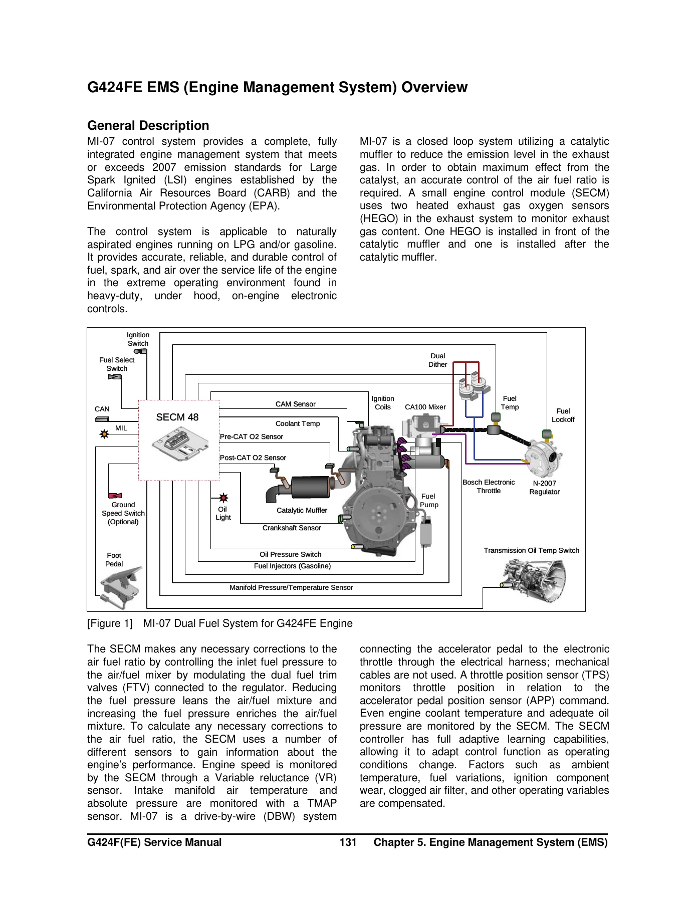
The EMS chapter is where the G424FE and G424F diverge, and the manual documents both. It covers the MI-07 control system general description, specifications, service standards, component locations, and the SECM and sensor/switch input tables. The G424FE overview explains the closed-loop LP system, the dual dither fuel trim valve arrangement, the MPI gasoline system, electronic throttle, ignition, exhaust system and three-way catalytic muffler, the SECM and its wiring diagrams. The G424F overview covers the open-loop LP system, electronic throttle, ignition and SECM. Following the overviews, the manual gives dedicated inspection and repair procedures for the SECM, camshaft position sensor, crankshaft position sensor, IAT and TMAP sensors, pre-catalyst and post-catalyst oxygen sensors, ECT sensor, LP fuel temperature sensor, accelerator pedal angle sensor, transmission oil temperature switch, ground speed limit switch and electronic throttle body, each with connector pinouts, circuit diagrams and test specifications.
LPG and MPI Gasoline Fuel Delivery
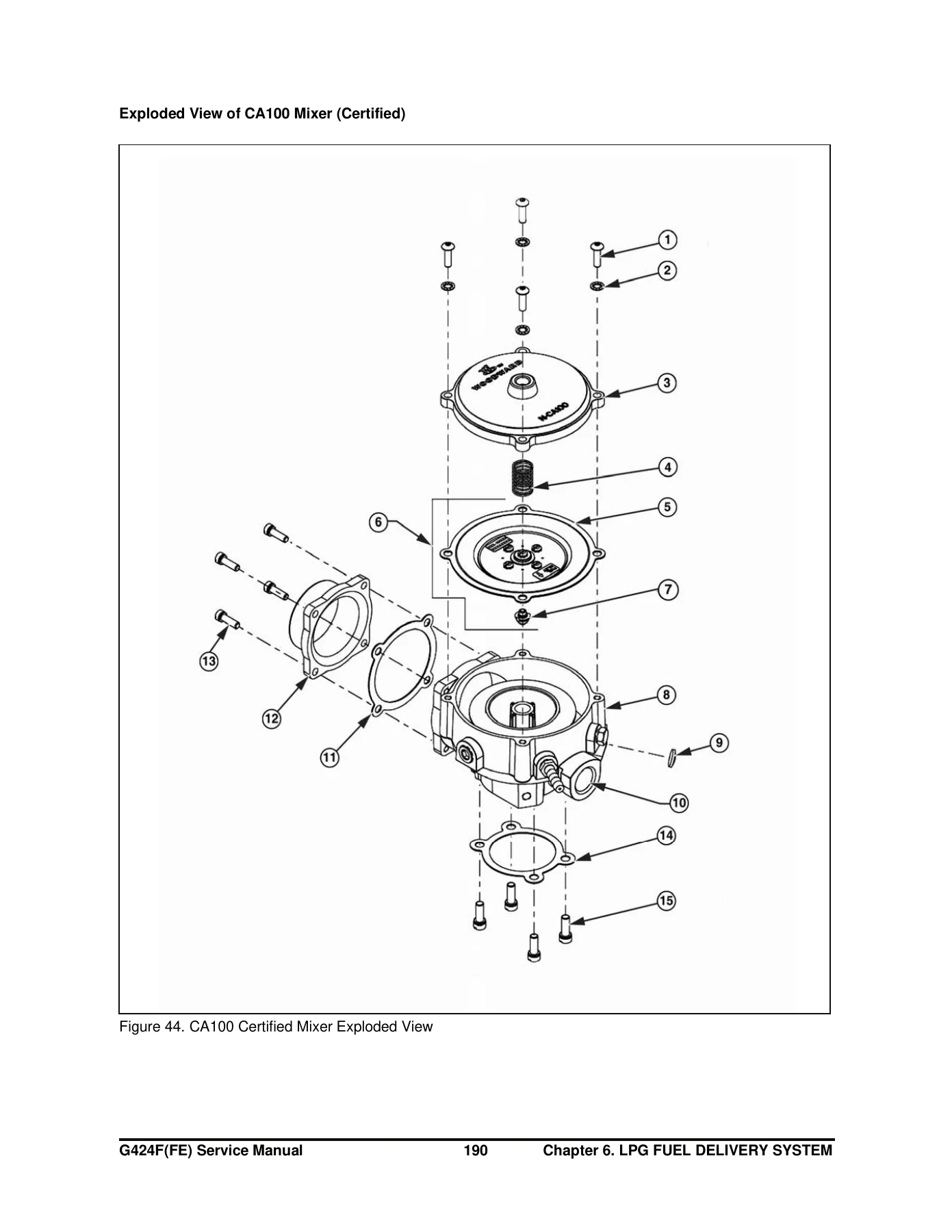
For LP engines the manual separates the certified G424FE system from the non-certified G424F system. Both sections cover removal and installation, hose connection diagrams with routing and maximum hose lengths, vacuum line identification and orientation notes, plus regulator and mixer service testing. The N-2007 regulator for the G424FE and the N-2001 regulator for the G424F each get a break-off secondary stage test and a primary stage pressure test procedure with the required hand vacuum pump, Magnehelic gauge and fitting hardware. Air Valve Vacuum (AVV) testing, connection of the MI-07 service tool, and idle mixture adjustment procedures follow, together with full parts descriptions and exploded views of the CA100 mixer and the regulator assemblies. The MPI gasoline chapter adds fuel pressure testing, injector inspection with resistance values and operation sound checks, and fuel pump removal including the built-in filter and pressure regulator.
Basic Troubleshooting and Advanced Diagnostics
Chapter 8 starts with preliminary checks, visual and physical inspection, a customer problem analysis sheet and a basic inspection procedure, then works through symptom troubleshooting guides for MPFI gasoline and LPG operation. Individual troubleshooting sections cover intermittents, surges and stumbles, engine cranking but not starting, lack of power, detonation and spark knock, backfire, dieseling and run-on, rough or unstable idle and stalling, cuts and misses, poor fuel economy and LPG exhaust smell, high idle speed, and excessive exhaust emissions or odours, each with probable cause and corrective action columns. Chart T-1 explains the restricted exhaust system check using backpressure measurement at the pre-catalyst oxygen sensor. Chapter 9 covers advanced diagnostics: reading diagnostic fault codes, displaying and clearing fault codes from SECM memory, fault action descriptions, the full fault list definitions table, and the complete diagnostic fault code table with probable fault, fault action and corrective action for every flash code. The appendix adds service tool software guidance for the MotoView system, ground speed limit setup, LPG and LPG fuel tank background, regulatory compliance notes and an abbreviations list.
What This Doosan Engine Service Manual Lets You Do
Whether you are pulling a cylinder head on a G424FE in a G30P-5, chasing an intermittent misfire on a dual fuel truck, or replacing a leaking N-2007 regulator, this manual gives you the procedure and the number you need rather than a guess. Torque values, clearances, service limits, sensor resistance ranges, fault-code definitions and adjustment procedures are all printed in the same place, so a rebuild stays within specification and a diagnostic session ends at the actual failed component instead of a parts cannon.
IMAGES PREVIEW
Delivered as an instant PDF download. No shipping, no waiting, no physical binder to lose in the shop. Open it on a laptop, tablet or phone, print the pages for the job in front of you, and keep the complete Doosan G424FE and G424F service manual on hand for every truck in the fleet. Buy once, use it for the life of the machine.
Reviews
There are no reviews yet.