
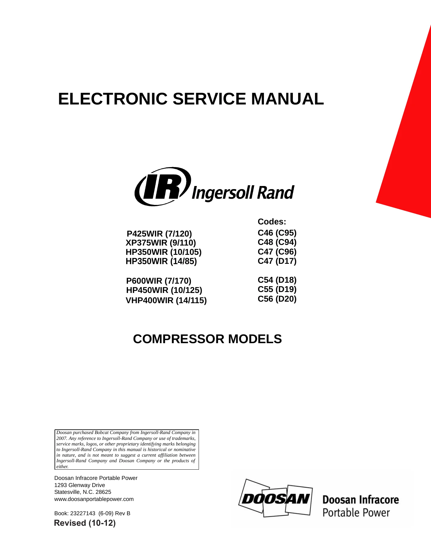
Doosan Ingersoll Rand P425WIR XP375WIR HP350WIR P600WIR HP450WIR VHP400WIR Electronic Service Manual 23227143
Original price was: $34.95.$21.95Current price is: $21.95.
Complete electronic service manual for Doosan Ingersoll Rand P425WIR, XP375WIR, HP350WIR, P600WIR, HP450WIR, and VHP400WIR portable air compressors. Covers WEDGE controller diagnostics, troubleshooting codes, wiring schematics, and connector repair procedures. Book 23227143, Rev B.
Description
The Doosan Ingersoll Rand P425WIR, XP375WIR, HP350WIR, P600WIR, HP450WIR, VHP400WIR Electronic Service Manual (Book 23227143, Rev B) is the complete electrical and electronic service reference for these portable air compressor models. This manual covers the WEDGE controller system, diagnostic code descriptions, troubleshooting procedures, system schematics, electrical component locations, harness connector information, and connector repair tool instructions for machines equipped with John Deere 4045HF285 and 6068HF285 engines.
File Details
- Manual Type: Electronic Service Manual
- Brand: Doosan Ingersoll Rand / Doosan Infracore Portable Power
- Models Covered: P425WIR (7/120), XP375WIR (9/110), HP350WIR (10/105), (14/85), P600WIR (7/170), HP450WIR (10/125), VHP400WIR (14/115)
- Engines: John Deere 4045HF285, John Deere 6068HF285
- Language: English
- Page Count: 137
- File Format: PDF
- Document Number: 23227143
- Revision: Rev B (Revised 10-12)
- Publication Date: 6-09
Chapters Covered
- Section 1 – General Information: Operational Theory, WEDGE Controller, Key Electrical Component Functions, Operating Controls and Instruments, Operational Information
- Section 2 – Settings: Reading and Setting Display Units, Wedge Service Diagnostic Display, Entering Machine ID for WEDGE Control Systems, Machine Models List
- Section 3 – Diagnostic Code Descriptions: Compressor Diagnostic Display Codes, Compressor Diagnostic Lights, John Deere Engine Models 4045HF285 and 6068HF285 Diagnostic Display Codes, John Deere 4045HF285 Engine ECM ALERT/SHUTDOWN Parameters
- Section 4 – Troubleshooting: Compressor Diagnostic Codes, Procedures and Techniques, Troubleshooting Flow Chart, Compressor Codes 1, 2, 3, 4, 10, 11, 29, 30, 32, 33, 34, 50, 51, 52, 53, 54, 56, 70, 71, and 73
- Section 5 – Troubleshooting: Electrical Circuits, Engine Start Circuit, Air Filter Restriction Switch Circuit
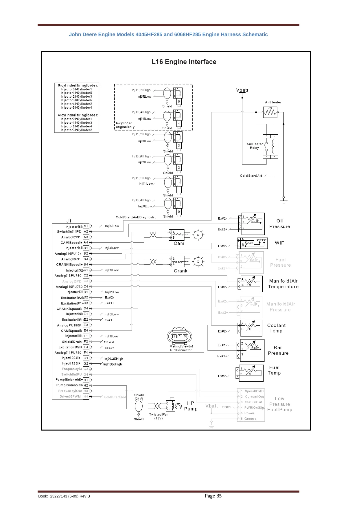
- Section 6 – System Schematics & Wiring Diagrams: John Deere Engine Models 4045HF285 and 6068HF285 Engine Harness Schematic
- Section 7 – Electrical Component Locations: Harness Connector Locations
- Section 8 – Electrical Parts List
- Section 9 – Harness Connector Information: Electrical Torque Specifications
- Section 10 – Tools and Repair Kits: Service Tools and Repair Kits, Connector Repair Kits, Terminal Crimp Tool Usage, Deutsch Crimp Tool HDT-48-00 Instructions, Deutsch DTC Series Connector Service Procedures, Deutsch DTM Series Connector Service Procedures, Deutsch HD10 Series Connector Service Procedures, Deutsch HD30 and HDP20 Series Connector Service Procedures, AMP Crimp Tool 58440-1 Instructions, AMP Ampsel Series Connector Service Procedures, Molex Crimp Tool Instructions, Molex Removal Tool Instructions
- Section 11 – Recommended Spare Parts
- Section 12 – Software Information: Software Updates
What This Electronic Service Manual Provides
This Doosan Ingersoll Rand electronic service manual is built around the WEDGE controller, the heart of the machine monitor and control system. It explains how the controller scans analog and digital inputs every 50 milliseconds, compares values against minimum and maximum thresholds, and issues ALERT or SHUTDOWN conditions when readings fall out of range. The manual details the controller’s three core functions: data collection and alarming, discharge air pressure control through engine throttle manipulation, and J1939 CAN network communication with the diesel engine ECM.
The manual explains the full sensor and transducer network, including the PT1 0-500 psi separator tank pressure transducer, PT2 0-100 psi regulation system pressure transducer, RT1 and RT2 10K ohm thermistor temperature sensors, and the U1 fuel level sensor. Each sensor circuit is documented with wiring diagrams, connector pinouts, and troubleshooting steps using the recommended simulators and test tools.
Diagnostic Code Troubleshooting
Each compressor diagnostic code gets its own dedicated troubleshooting section with explanation, effect, and step-by-step procedures. The manual covers Code 1 (Low Engine Speed), Code 2 (High Engine Speed), Code 3 (Engine Crank Time Exceeded), Code 4 (Low Fuel Level), Code 10 (Engine Not Responding To Throttle Command), Code 11 (Too Many Start Attempts During Auto Start), Code 29 (Engine SHUTDOWN: Reason Unknown), Code 30 (High Airend Discharge Temperature), Code 32 (Airend Discharge Temperature Sensor Fault), Code 33 (Separator Tank Pressure Sensor Fault), Code 34 (Separator Tank Pressure Greater Than 20 psi at Crank), Code 50 (High Separator Tank Temperature), Code 51 (Machine ID Not Installed), Code 52 (IQ Filter Restriction), Code 53 (Separator Tank Temperature Sensor Fault), Code 54 (Regulation System Pressure Sensor Fault), Code 56 (Minimum Start Pressure Not Met), Code 70 (Serial Communications Failure), Code 71 (Engine ECM Communication Failure), and Code 73 (Auto Start/Stop Controller Communication Failure).
WEDGE Service Diagnostic Display and Machine ID Configuration
The manual walks through reading and setting display units, accessing the WEDGE service diagnostic display, and entering the correct machine ID for WEDGE control systems. The service diagnostic display provides access to parameters including engine RPM, regulation system pressure, separator tank pressure, airend discharge temperature, separator tank temperature, target engine RPM, engine coolant temperature, engine oil pressure, engine intake manifold temperature, engine fault codes, engine throttle position, engine hours, and engine load at speed.
Wiring Schematics and Electrical Component Locations
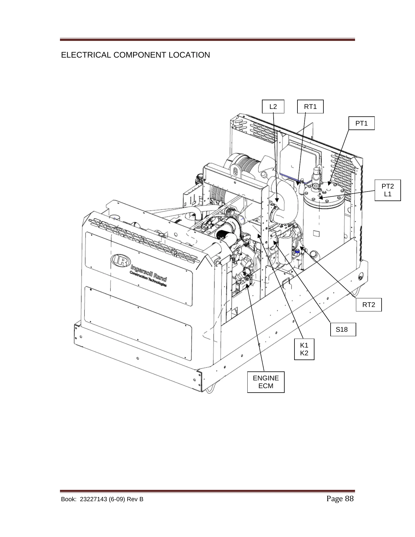
System schematics and wiring diagrams show the connections between the WEDGE controller, engine ECM, terminating resistors, and all sensors and switches. The John Deere 4045HF285 and 6068HF285 engine harness schematic provides injector wiring, cam and crank sensor circuits, oil pressure, coolant temperature, fuel pressure, manifold air temperature, rail pressure, and fuel temperature sensor connections. Electrical component location illustrations show the physical placement of PT1, PT2, RT1, RT2, S18, K1, K2, and the engine ECM within the machine.
Connector Repair and Tooling
A substantial portion of this electronic service manual is dedicated to connector service procedures. It covers Deutsch DTC, DTM, HD10, HD30, and HDP20 series connectors, AMP Ampseal connectors, and Molex CMC connectors. Each section includes insertion and removal procedures, terminal crimp tool usage, wire strip lengths, and terminal part numbers. The manual also lists recommended service tools and repair kits, including digital multimeters, thermistor simulators, pressure transducer simulators, terminal removal tools, and crimp tools.
Operational Information by Model Group
The manual provides model-specific operational information for two groups. For P600WIR (7/170), HP450WIR (10/125), and VHP400 (14/115), and separately for P425WIR (7/120), XP375WIR (9/110), HP350WIR (10/105), and (14/85), the startup, load, and shutdown sequences are documented with engine speed thresholds, solenoid valve states, and pressure setpoints.
Who This Doosan Ingersoll Rand Electronic Service Manual Is For
This manual is for technicians, fleet maintenance personnel, and equipment owners who need to diagnose and repair the electrical and electronic systems on these Doosan portable air compressors. It is particularly useful for anyone working with the WEDGE controller, troubleshooting diagnostic codes, tracing wiring faults, or repairing the sealed connectors used throughout the machine harnesses.
Get Instant Access to the Doosan Ingersoll Rand P425WIR XP375WIR HP350WIR P600WIR HP450WIR VHP400WIR Electronic Service Manual
With this electronic service manual, you can read and clear diagnostic codes, trace electrical faults through the WEDGE controller and engine ECM, test sensors and transducers with the correct procedures, repair Deutsch, AMP, and Molex connectors to factory standards, and understand the exact startup and load sequences for each model group. Having the correct diagnostic procedures and wiring diagrams on hand means faster repairs, fewer replaced parts that were not the problem, and machines back in service sooner.
IMAGES PREVIEW
Delivered as an instant PDF download, this Doosan Ingersoll Rand service manual is available immediately after checkout. No shipping, no waiting. Read it on any device — laptop, tablet, or smartphone — and print the pages you need for the shop floor. Whether you are troubleshooting a Code 30 high airend discharge temperature, entering a new machine ID into a replacement WEDGE controller, or repairing a damaged connector, this manual gives you the procedures and specifications to do the job right.
Reviews
There are no reviews yet.