Ducati Multistrada 1000 Service Manual 2003 – 2006 – PDF DOWNLOAD
Original price was: $56.95.$20.95Current price is: $20.95.
Ducati Multistrada 1000 Service Manual 2003 – 2006
Description
Ducati Multistrada 1000 Service Manual 2003 – 2006
FILE DETAILS:
Ducati Multistrada 1000 Service Manual 2003 – 2006
Language : English
Pages : 593
Downloadable : Yes
File Type : PDF
Size: 49.2 MB
DESCRIPTION:
Ducati Multistrada 1000 Service Manual 2003 – 2006
HOW TO USE THE MANUAL:
This manual has been prepared for Ducati Authorized Service Centers and workshop personnel involved in the maintenance and repair of Ducati motorcycles. It gives fundamental information on how to work in perfect harmony with the concepts of “good technique” and “safety on work sites” for servicing or replacing of original spare parts both for chassis and engine concerning this motorcycle. All operations described in this manual must be carried out by senior skilled technicians, who are requested to strictly follow the Manufacturer’s instructions. Some information has been intentionally omitted, as, at our advice, a specialized technician must have this technical background. Additional information on how to install the different components is provided in the spare parts catalogue.
Manual layout:
This manual is divided in sections, each identified by a letter. Each section includes several chapters, which are numbered consecutively and may be divided in paragraphs. The repair procedures described in this manual include the necessary disassembly and re-assembly instructions, i.e. the full procedure is detailed starting with the motorcycle fully assembled until bringing it back to the original condition.
TABLE OF CONTENTS:
Ducati Multistrada 1000 Service Manual 2003 – 2006
Section A
DESCRIPTION 0
1 – HOW TO USE THE MANUAL 3
Manual layout 4
2 – SYMBOLS – ABBREVIATIONS –
REFERENCES 5
Product specifications 8
3 – DANGEROUS PRODUCTS –
WARNINGS 10
General safety rules 10
General maintenance indications 12
Section B
MODEL-SPECIFICI NFORMATION0
1 – IDENTIFICATION DATA 3
Section C
SPECIFICATIONS 0
1.1 -TECHNICAL DATA 10
Description 10
Colours 11
Transmission 11
Timing/valves 11
Lubrication system 12
Cylinder / piston 12
Gearbox 13
Cooling system 13
Front wheel 13
Front suspension 13
Rear wheel 14
Rear suspension 14
Hydraulic brakes 14
Charging system / generator 15
Ignition system 15
Control unit 15
Lights / instrument panel 15
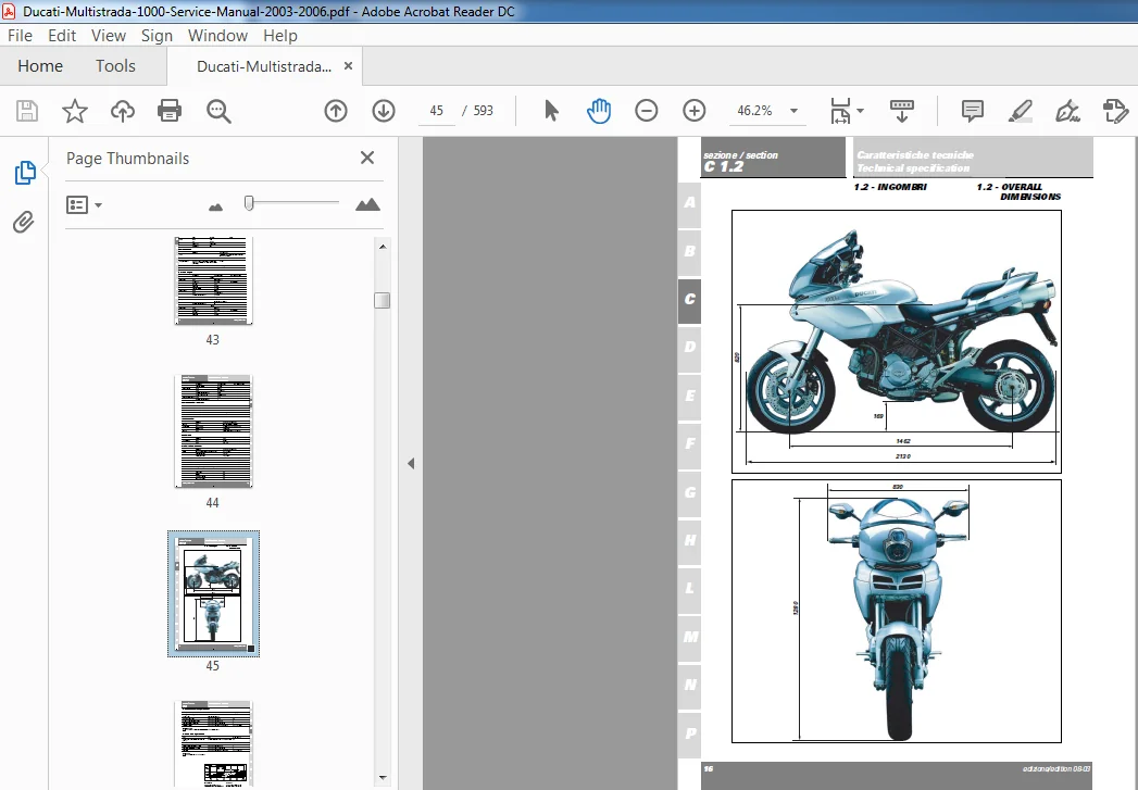
1.2 -OVERALL DIMENSIONS 16
2 – FUELS AND LUBRICANTS 17
3 – TORQUE SETTINGS 27
Frame torque settings 27
Engine torque settings 32
4 – SERVICE TOOLS 42
Engine special tools 42
Frame specific tools
Section D
USE AND MAINTENANCE
OPERATIONS 0
1 – PRELIMINARY CHECKS 3
Running-in precautions 3
Pre-ride checks 4
2 – STARTING – ENGINE WARM-UP 6
Starting the engine 6
3 – ROUTINE MAINTENANCE TABLE 9
4 – MAINTENANCE OPERATIONS 11
Turning off the “Service” warning on the instrument panel 11
Checking the engine oil level 12
Changing the engine oil and filter cartridge 13
Checking valve clearances 15
Changing the fuel filter 17
Changing and cleaning the air filter 18
Changing the brake fluid 19
Draining the brake circuits 21
Filling the braking circuits 22
Changing the clutch fluid 24
Draining the clutch circuit 25
Filling the clutch circuit 26
Adjusting steering bearings play 28
Adjusting the clutch lever and the front brake lever 29
Chain adjustment 30
Checking brake pad wear. Changing brake pads 32
Adjusting the throttle cables 34
Adjusting the position of the gear change and rear brake
pedals 36
Adjusting the rear shock absorber 37
Adjusting the front fork 38
Changing motorcycle track alignment 39
5 – TESTERS 40
Mathesis tester description 41
Tester connection to the bike 42
Checking and adjusting timing belt tension 44
Adjusting the throttle body 48
Checking engine oil pressure 52
Checking cylinder compression 54
Section E
FAIRING 0
1 – HEADLIGHT FAIRING – REAR-VIEW
MIRRORS 3
Removing the rear-view mirrors 4
Refitting the rear-view mirrors 4
Removing the mobile headlight fairing 5
Refitting the mobile headlight fairing 5
Removing the fixed headlight fairing 6
Refitting the fixed headlight fairing 7
2 – FAIRING 8
Removing the left fairing 9
Refitting the left fairing 9
Removing the front conveyor 10
Refitting the front conveyor 10
Removing the upper left fairing 11
Refitting the upper left fairing 11
Removing the upper right fairing 12
Refitting the right fairing 14
3 – FUEL TANK-AND-SEAT ASSEMBLY,
SIDE PANELS AND FRONT
MUDGUARD 15
Removing the passenger seat 17
Refitting the passenger seat 17
Removing the rear side panels 18
Notes on rear side panel installation 18
Removing the fuel tank-and-seat assembly 19
Refitting the fuel tank-and-seat assembly 21
4 – FRONT MUDGUARD 23
Removing the front mudguard 23
Refitting the front mudguard 23
Section F
CONTROLS – DEVICES 0
1 – THROTTLE CONTROL – STARTER 3
Removing the throttle control 4
Refitting the throttle control 4
2 – CLUTCH HYDRAULIC CONTROL 6
Removing the clutch cylinder assembly 7
Fitting the clutch cylinder assembly 7
Removing the clutch transmission unit 8
Refitting the clutch transmission unit 9
3 – FRONT BRAKE CONTROL 11
Removing the front brake master cylinder 12
Refitting the front brake master cylinder 13
4 – REAR BRAKE CONTROL 14
Removing the rear brake master cylinder 15
Refitting the rear brake master cylinder 17
5 – GEAR CHANGE CONTROL 21
Removing the gear change control 22
Disassembling the gear change control 22
Refitting the gear change control 22
6 – RELEASING MECHANISMS 23
Removing the passenger seat releasing mechanism 24
Removing the glove compartment releasing mechanism 24
Section G
WHEELS – SUSPENSIONS –
BRAKES 0
1 – FRONT WHEEL 3
Removing the front wheel 4
Overhauling the front wheel 5
Refitting the front wheel 7
2 – FRONT FORK 8
Removing the front fork 9
Overhauling the front fork 10
Fitting the front fork 18
3 – FRONT BRAKE 19
Braking system maintenance 20
Removing the front brake system 20
Overhauling the front brake components 21
Refitting the front brake system 22
4 – REAR WHEEL 24
Removing the rear wheel 25
Overhauling the rear wheel 26
Refitting the rear wheel 27
5 – REAR SWINGARM 28
Removing the rear eccentric hub 30
Refitting the rear eccentric hub 31
Removing the rear swingarm 32
Checking the swingarm pivot 33
Overhauling the rear swingarm 34
Refitting the rear swingarm 36
6 – REAR BRAKE 38
Removing the rear brake system 39
Refitting the rear brake system 41
7 – REAR SUSPENSION 42
Rear suspension unit 43
Removing the monoshock absorber 44
Overhauling the monoshock absorber 44
Removing the rear suspension rocker arm 45
Overhauling the rear suspension rocker arm 46
Removing and overhauling the shock absorber linkage 47
Refitting the rear suspension 48
8 – FINAL DRIVE 50
Inspecting the final drive 51
Removing the chain front sprocket 52
Changing the gearbox secondary shaft seal 53
Removing the rear sprocket 54
Washing the chain 55
Lubricating the chain 55
Section H
FRAME 0
1 – HANDLEBAR 3
Removing the handlebar 4
Refitting the handlebars 5
2 – STEERING 6
Adjusting steering bearing play 7
Adjusting the steering angle 7
Disassembling the headstock parts 8
Reassembling the headstock parts 9
4 – FOOTPEG SUPPORTS 12
Removing the footpegs 13
Refitting the footpegs 15
5 – STANDS 18
Removing the side stand 19
Refitting the side stand 20
6 – FRAME INSPECTION 21
Removing the frame and related components 22
Removing the front subframe 22
Removing the rear grab handle 22
Checking the frame 22
the rear grab handle 25
Refitting the front subframe 25
7 – TAIL LIGHT AND NUMBER PLATE
HOLDER 26
Removing the tail light number plate holder 27
Refitting the number plate holder and tail light 28
8 – ACCESSORIES: CENTER STAND 29
Installing the center stand 30
Removing the center stand 34
Refitting the center stand 34
Section L
FUEL SYSTEM / EXHAUST
SYSTEM 0
1 – DESCRIPTION OF FUEL SYSTEM 3
2 – FUEL TANK ASSEMBLY 5
Removing and refitting the fuel tank assembly 6
Replacing the breather valve and the fluid recovery reservoir 7
Replacing the fuel tank flange and the fuel sensor 9
Replacing the fuel filler plug assembly 12
6 – THROTTLE BODY 15
Removing the throttle body 16
Refitting the throttle body 18
7 – AIR INTAKE 20
Removing the air box 21
Refitting the airbox 23
8 – EXHAUST SYSTEM 26
Catalytic converter operating principle 27
Removing the exhaust system 29
Refitting the exhaust system 32
10 -CANISTER FILTER 36
Canister filter system (USA versions only) 37
Removing the canister filter 38
Refitting the canister filter 38
Section M
IGNITION – INJECTION SYSTEM0
1 – DESCRIPTION OF THE FUEL
INJECTION-IGNITION SYSTEM 3
General information on the fuel injection-ignition system 3
Fuel circuit 6
Intake air circuit 7
Operating stages 8
2 – SYSTEM DIAGRAM 9
Fuel injection-ignition system diagram 9
3 – FUEL INJECTION-IGNITION SYSTEM
COMPONENTS 12
Electronic control unit 12
Electric injector 15
Stepper motor 16
Throttle position sensor 17
Rpm/timing sensor 17
Air pressure sensor 17
Air temperature sensor 18
Spark plug 19
Coil 20
Injection relay 21
CAN line 22
4 – INSTRUMENTS 23
Instrument panel system 23
Display Functions 26
Instrument Panel Functions 37
Section N
ENGINE 0
1 – REMOVING – REASSEMBLING THE
COMPLETE ENGINE 4
Removing the engine 6
Reassembling the engine 7
2.1 -LUBRICATION SYSTEM: OIL PUMP 8
Lubrication system diagram 9
Removing the oil pump 12
Disassembling the oil pump 12
Overhauling the oil pump 13
Reassembling the oil pump 13
Refitting the oil pump 14
2.2 -LUBRICATION SYSTEM:
OIL COOLER 15
Removing the oil cooler 16
Checking the oil cooler 16
Refitting the oil cooler 17
2.3 -LUBRICATION SYSTEM: OIL
BREATHER 20
Removing the oil breather 21
Refitting the oil breather 21
4.1 -HEAD UNIT: CHECKS AND
ADJUSTMENTS 23
Checking and adjusting valve clearance 24
Checking engine timing 28
4.2 -HEAD UNIT: SIDE COVERS / TIMING
SYSTEM 30
Removing the timing side covers 31
Timing system disassembly 32
Disassembling the mobile tensioner 34
Disassembling the belt rollers 34
Reassembling the timing system 35
Refitting the timing side covers 41
4.3 -HEAD UNIT : CAMSHAFTS 42
Removing the engine oil temperature sensor 44
Refitting the engine oil temperature sensor 44
Disassembling the intake manifold 45
Refitting the intake manifolds 45
Removing the side caps 46
Removing the valve covers 47
Refitting the valve covers 47
Removing the camshafts 48
Checking camshafts 49
Checking the oil seals 49
Refitting the camshaft
Refitting the cam covers 51
4.4 -HEAD UNIT: VALVES – ROCKER
ARMS 52
Disassembling the engine heads 53
Overhauling the head parts 57
Reassembling the head 62
5 – CYLINDER / PISTON ASSEMBLY 69
Removing cylinder / piston assy 70
Overhauling the cylinder / piston assy 72
Refitting cylinder / piston assy 76
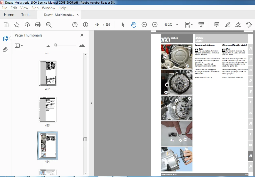
6.1 -CLUTCH ASSEMBLY: CLUTCH 78
Clutch unit 79
Disassembling the clutch 81
Checking and overhauling the clutch components 85
Reassembling the clutch 86
6.2 -CLUTCH ASSEMBLY: CLUTCH
COVER 89
Removing the clutch cover 90
Disassembling the clutch cover 91
Reassembling the clutch cover 92
Refitting the clutch cover 93
6.3 -CLUTCH ASSEMBLY: PRIMARY
DRIVE GEARS 94
Disassembling the primary drive gears 95
Fitting the primary drive gear and checking meshing play 97
7.1 -GEARBOX: LEVER ASSEMBLY 99
Removing the gear selector levers 100
Removing the gear stopper and ratchet 101
Reassembling gear stopper and ratchet 101
Reassembling the gear selector lever 102
7.2 -GEARBOX ASSEMBLY: GEARBOX
SHAFTS 103
Removing the gearbox 105
Disassembling the gearbox shafts 106
Overhauling the gearbox 110
Inspecting the gear selector forks 112
Inspecting the fork selector drum 112
Reassembling the gearbox shafts 113
Reassembling the gearbox 114
8 – FLYWHEEL – GENERATOR 116
Removing the generator cover 118
Disassembling the generator cover 119
Removing the flywheel – generator assembly 120
Checking the flywheel – generator assembly 121
Refitting flywheel / generator assembly 123
Reassembling generator cover 124
Checking the engine sensor air gap 125
9.1 -CASING UNIT: OUTER
COMPONENTS 126
Removing outer components 127
Reassembling the outer parts 128
Removing the timing lay gear 130
Reassembling the timing lay gear 130
Removing the starter motor driven gear 131
Reassembling the starter motor driven gear 131
9.2 -CASING UNIT: CRANKCASES 132
Opening the casings 133
Overhauling the casings 134
Main bearings 136
Reassembling the casings 137
Shimming the shafts 139
Closing the casings 147
9.3 -CASING UNIT: CONNECTING
RODS 149
Removing the connecting rods 150
Disassembling the connecting rods 150
Overhauling the connecting rods 151
Reassembling the connecting rods 155
Refitting the connecting rod unit 156
Section P
ELECTRIC SYSTEM 0
1 – WIRING DIAGRAM 4
Electric system key 6
Fuse key 6
Wire color coding – wiring diagram 7
Arrangement of wiring on frame 7
Diagram A 10
Diagram AA 11
Diagram AB 11
Diagram AC 12
Diagram AD 12
Diagram AE 13
Diagram B 14
Diagram C 15
Diagram D 16
Diagram E 17
Diagram F 18
Diagram G 19
Diagram H 20
Diagram I 21
Diagram J 22
Diagram K 23
Diagram L 23
Diagram M 24
Diagram N 24
Diagram O 25
Diagram P 25
Diagram Q 26
Diagram R 27
Diagram S 28
Diagram T 29
Diagram U 30
Diagram V 31
Diagram W 32
Diagram X 32
Diagram Y 33
Diagram Z 34
2 – CHARGING SYSTEM – BATTERY 35
Checking the charging system 35
Charging methods 35
Battery 37
Battery mount 39
Generator 40
Rectifier – regulator 41
3 – ELECTRIC STARTING 43
Electric starting system 44
Starter motor 46
Starter contactor 48
4 – LIGHTING DEVICES 49
Removing the instrument panel 49
Changing light bulbs 50
High beam relay 53
Beam setting 54
5 – INDICATORS AND LIGHTING
SYSTEM 55
Checking the indicators and lighting system components 55
Changing bulbs 60
6 – PROTECTION AND SAFETY DEVICES 61
Checking protection and safety devices components 61
Fuses check 63
8 – IMMOBILIZER AND TRANSPONDER 64
9 – TESTERS 72
How to use the multimeter to check electric systems 72
DUCATI MULTISTRADA 1000 SERVICE MANUAL 2003 – 2006 – PDF DOWNLOAD:
IMAGES PREVIEW OF THE MANUAL:
PLEASE NOTE:
- This is the SAME MANUAL used by the dealerships to diagnose your vehicle
- No waiting for couriers / posts as this is a PDF manual and you can download it within 2 minutes time once you make the payment.
- Your payment is all safe and the delivery of the manual is INSTANT – You will be taken to the DOWNLOAD PAGE.
- So have no hesitations whatsoever and write to us about any queries you may have : heydownloadss @gmail.com
Raul Kenneth –
It was ok all i want is the manual that I paid for