Dymind DF50 Auto Hematology Analyzer Service Repair Manual PDF
Original price was: $120.00.$34.95Current price is: $34.95.
Complete professional service manual for Dymind DF50 Auto Hematology Analyzer. This comprehensive 121-page technical guide covers full CBC+DIFF blood analysis systems including WBC, RBC, PLT, HGB, and BASO measurements. Includes detailed hydraulics system diagrams, optical assembly procedures, hardware configurations, component replacement instructions, software upgrade procedures, calibration methods, alarm codes, and troubleshooting solutions. Essential for biomedical technicians servicing laboratory hematology equipment.
Description
Dymind DF50 Auto Hematology Analyzer Service Repair Manual PDF DOWNLOAD
DESCRIPTION
Professional Dymind DF50 Auto Hematology Analyzer Service Manual
This is the official comprehensive service manual for the Dymind DF50 Auto Hematology Analyzer manufactured by Shenzhen Dymind Biotechnology Co., Ltd. Designed for qualified biomedical equipment technicians (BMETs), clinical engineers, and laboratory service professionals, this manual provides complete technical documentation for maintenance, repair, calibration, and troubleshooting of automated hematology analysis systems.
Analyzer Model Covered:
- Dymind DF50 – Auto Hematology Analyzer with CBC+DIFF capability
Analysis Capabilities:
- Complete Blood Count (CBC) with differential
- WBC (White Blood Cell) measurement with differential
- RBC (Red Blood Cell) and PLT (Platelet) analysis
- HGB (Hemoglobin) measurement
- BASO (Basophil) detection
- Multiple measurement modes (Whole-blood and Predilute)
Manufacturer: Shenzhen Dymind Biotechnology Co., Ltd. (DYMIND)
Device Classification: In Vitro Diagnostic (IVD) Medical Device
Application: Clinical laboratory hematology testing
Complete Manual Contents:
CHAPTER 1: MANUAL OVERVIEW
1.1 – Who Should Read This Manual: Critical qualifications required for service personnel:
- Comprehensive knowledge of electrical circuits and hydraulics
- Understanding of reagent chemistry and handling
- Quality control expertise
- Advanced troubleshooting capabilities
- Skilled operation of hematology analyzers
- Proficiency with mechanical tools and terminology
- Digital voltmeter and oscilloscope operation skills
- Ability to analyze electrical schematics and hydraulics diagrams
1.2 – Symbols and Legends:
- Safety symbol definitions (Personal injury warnings)
- Equipment damage prevention symbols
- Biohazard and infection control symbols
- Device labeling symbol explanations:
- Biohazard indicators
- Protective grounding symbols
- Type B applied part designation
- IVD (In Vitro Diagnostic) marking
- Lot numbers and expiration dates
- Storage temperature requirements
- Manufacturer identification
1.3 – Safety Instructions:
- Comprehensive safety protocols for service personnel
- Electrical shock prevention procedures
- Explosion hazard warnings (combustible gases/liquids)
- Bio-contamination safety procedures
- Mechanical hazard warnings (sample probe, moving parts)
- Reagent handling safety guidelines
- Personal protective equipment (PPE) requirements
- Electrostatic discharge (ESD) protection protocols
- Biohazardous waste disposal regulations
- Service environment safety requirements
CHAPTER 2: INSTRUMENT CONFIGURATION (67 Pages)
2.1 – Mechanical Components:
- Front Panel Components:
- Aspirate key operation
- Sample probe assembly
- Status indicator lights
- Touch screen interface
- Side Panel Access:
- LAN network interface
- USB interface locations
- Right side door access
- Left side maintenance door
- Rear Panel Connections:
- Power switch and input connector
- Cooling fan assembly
- Waste outlet connector
- Diluent inlet connector
- BNC sockets (diluent and waste sensors)
- Ground studs
- Internal Component Layout:
- Sampling assembly location
- Main control panel position
- Power assembly placement
- Counting bath assembly
- Electromagnetic valve assembly
- Negative-pressure chamber
- Preheating bath assembly
- Pinch valve locations
- Liquid pump assembly
- Optical assembly
- Reagent testing panel
- Sample syringe
2.2 – Hydraulics System (38 Pages):
System Overview: Complete hydraulics architecture for blood sample processing and analysis
2.2.1 – Hydraulic System Schematic Diagram:
- Complete flow path visualization
- Component interconnections
- Pressure and vacuum pathways
2.2.2 – Overall Unit Hydraulics Diagram:
- Master hydraulics schematic
- All valve positions and functions
- Tubing routing and connections
- Sensor integration points
2.2.3 – DIFF/WBC Measurement Channel:
- Dosing syringe operation
- WBC reaction bath function
- Flow chamber design
- Tubing and valve configuration
- Differential white cell counting principles
2.2.4 – HGB Measurement Channel:
- Hemoglobin measurement methodology
- Dosing syringe for HGB
- WBC reaction bath dual usage
- HGB emission light source
- HGB receiving tube optics
- Tubing and valve routing
2.2.5 – RBC/PLT Measurement Module:
- Red blood cell counting principles
- Platelet detection methodology
- Dosing syringe specifications
- RBC/PLT counting bath assembly
- Impedance measurement system
- Tubing and valve integration
2.2.6 – Sampling and Blood-dispensing Module:
- Sample probe mechanics and operation
- Sample syringe precision dosing
- Swab cleaning system
- Sampling assembly X-Y positioning
- Whole-blood aspiration sequence
- Predilution sample handling
2.2.7 – Power Supply and Waste Discharge Module:
- Vacuum chamber operation
- Liquid pump specifications
- Waste handling system
- Valve control for waste routing
- Tubing management
- Pressure regulation
2.2.8 – Status Monitoring Module:
- Optocoupler sensors
- Temperature sensors
- Pressure sensors (sheath flow)
- Reagent level detection
- Waste level monitoring
- System status feedback
2.2.9 – Hydraulic Components:
- Electromagnetic Valves: Complete specifications and operations
- Pinch Valves: Design and function
- Dosing Syringes: Precision volume control
- Reaction Baths: WBC and RBC bath assemblies
- Pumps: Liquid pump specifications
- Pressure Chambers: Vacuum and positive pressure systems
- Tubing: Material specifications and routing
- Connectors: All hydraulic connections detailed
2.2.10 – Main Measurement Modes:
- Whole-blood CBC+DIFF Mode:
- Complete measurement sequence
- Sampling procedures
- Dispensing operations
- Dilution ratios
- Reagent mixing
- Measurement timing
- Predilute Mode:
- Manual dilution procedures
- Sample volume requirements
- Modified measurement sequences
- Background Count Procedures
- Cleaning Cycles
- Calibration Measurements
2.2.11 – Hydraulics Maintenance:
- Preventive maintenance schedules
- Cleaning procedures for all components
- Valve inspection and replacement
- Syringe calibration verification
- Bath cleaning protocols
- Tubing replacement guidelines
- Leak detection and repair
2.2.12 – Troubleshooting Common Hydraulics Problems: Comprehensive troubleshooting guide including:
- High background counts
- Unstable counts
- Clogged apertures
- Valve failures
- Pump malfunctions
- Pressure irregularities
- Reagent flow problems
- Sample aspiration failures
- Dispensing errors
- Cleaning cycle failures
- Leak diagnostics
- Air bubble problems
- Temperature instabilities
2.3 – Hardware System (19 Pages):
2.3.1 – Main Control Panel:
- Microprocessor Architecture:
- CPU specifications
- Memory configuration (RAM/ROM)
- Processing capabilities
- Circuit Board Layout:
- Component locations
- Test points
- Connector pinouts
- Power distribution
- Interface Connections:
- Touch screen interface
- USB connectivity
- LAN network connection
- Sensor inputs
- Motor drivers
- Valve drivers
- Pump control signals
- Power Supply Circuits:
- Voltage regulation
- Current specifications
- Protection circuits
- Fault detection
- Signal Processing:
- Analog to digital conversion
- Impedance measurement circuits
- Optical signal processing
- Data acquisition timing
2.3.2 – Other Panels:
- Reagent Testing Panel:
- Level detection circuits
- Quality monitoring
- Temperature measurement
- Optical Preamplifier Panel:
- Signal amplification
- Noise filtering
- Gain adjustment
- Laser Driver Panel:
- Laser power control
- Current regulation
- Safety interlocks
- Sampling Control Panel:
- Motor drivers
- Position sensors
- Limit switch inputs
2.4 – Optical System (8 Pages):
Laser-based Flow Cytometry System:
2.4.1 – Integral Replacement of Optical Assembly:
- Complete optical bench removal
- Alignment preservation
- Installation procedures
- Post-installation verification
2.4.2 – Replacing Optical Preamplifier Panel:
- Preamplifier removal steps
- Connector disconnection
- New panel installation
- Signal verification
2.4.3 – Replacing Laser Driver Panel:
- Safety procedures for laser service
- Driver panel access
- Replacement procedures
- Laser power verification
- Alignment check
2.4.4 – Fine Tuning of Flow Chamber:
- Critical Alignment Procedures:
- Laser beam alignment
- Flow chamber positioning
- Forward scatter optimization
- Side scatter optimization
- Fluorescence channel alignment (if applicable)
- Adjustment Tools Required
- Verification Measurements
- Alignment Tolerances
2.4.5 – Replacement of High-angle Receiving Plate:
- Side scatter detector access
- Receiving plate removal
- Optical surface cleaning
- Installation and alignment
- Signal verification
2.4.6 – Common Problems and Solutions:
- Low signal strength troubleshooting
- High background noise
- Unstable signals
- Laser power fluctuations
- Alignment drift
- Detector failures
- Optical contamination
- Flow chamber clogs affecting optics
CHAPTER 3: REPAIRS (45 Pages)
3.1 – Overview:
- General repair procedures
- Safety precautions during repairs
- Required tools and equipment
- ESD protection requirements
3.2 – Preparatory Work Before Repairs:
3.2.1 – Disassembling the Left Side Panel:
- Panel fastener locations
- Safe removal procedures
- Cable management
- Access to optical system
3.2.2 – Open the Right Side Door:
- Door release mechanism
- Access to hydraulics components
- Safety interlocks
3.2.3 – Disassembling the Panel Cover:
- Front panel removal
- Top cover access
- Internal component exposure
3.3 – Display Screen Assembly Replacement:
3.3.1 – Replacing the Touch Screen:
- Touch screen calibration backup
- Connector disconnection
- Mounting bracket removal
- New screen installation
- Cable routing
- Touch screen calibration procedures
3.4 – Sampling Assembly Replacement:
3.4.1 – Replacing the Sample Probe:
- Probe removal from assembly
- Cleaning port access
- New probe installation
- Height verification
- Leak testing
3.4.2 – Replacing the Optocoupler:
- Optocoupler sensor location
- Electrical disconnection
- Mounting hardware removal
- New sensor installation
- Position verification
3.4.3 – Replacing the Sampling Assembly in X- or Y-direction:
- Motor and drive mechanism removal
- Belt or lead screw replacement
- Position encoder replacement
- Lubrication procedures
- Limit switch adjustment
- Home position calibration
3.5 – Power Assembly Replacement:
- Main power supply removal
- Fuse locations and ratings
- Power cable routing
- Voltage verification
- Safety testing
3.6 – Hydraulics Components Replacement:
3.6.1 – Replacing Valve Assembly:
- Electromagnetic valve removal
- Pinch valve replacement
- Tubing disconnection
- Installation procedures
- Leak testing
- Functional verification
3.6.2 – Replacing Liquid Pump Assembly:
- Pump motor disconnection
- Tubing removal
- Mounting bracket access
- New pump installation
- Prime procedures
- Flow rate verification
3.6.3 – Replacing Negative-pressure Chamber Assembly:
- Vacuum chamber access
- Pressure sensor disconnection
- Tubing removal
- New chamber installation
- Leak testing
- Vacuum verification
3.7 – Sheath Flow Syringe Assembly Replacement:
3.7.1 – Replacing the Syringe:
- Syringe removal from stepper motor
- Seal inspection
- New syringe installation
- Home position calibration
- Volume verification
3.7.2 – Replacing the Motor:
- Stepper motor disconnection
- Syringe removal
- Motor mounting hardware
- Encoder connection
- Motor direction verification
- Step calibration
3.8 – WBC and RBC Bath Assemblies Replacement:
3.8.1 – Dismantling and Replacing WBC Bath Assembly:
- Temperature sensor removal
- Heater element disconnection
- Electrode removal
- Tubing disconnection
- Bath removal and installation
- Temperature calibration
- Electrode testing
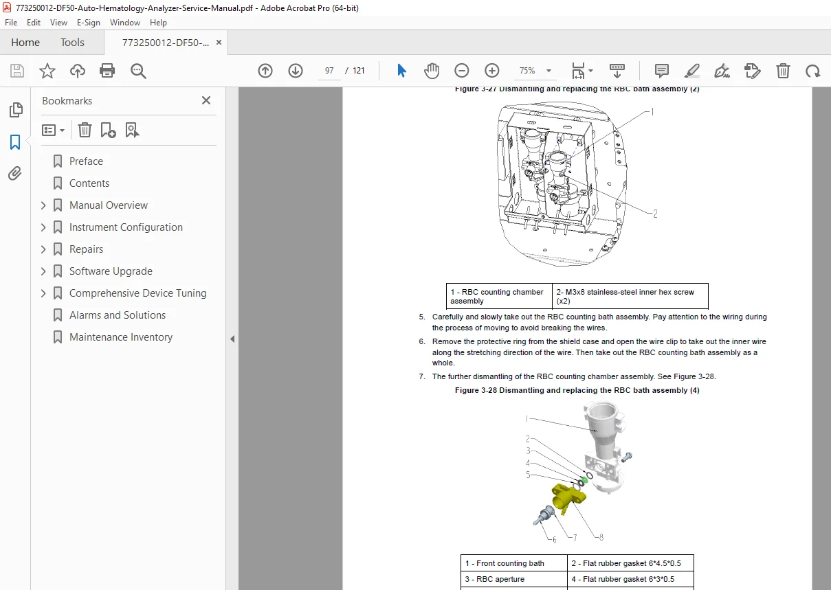
3.8.2 – Dismantling and Replacing RBC Bath Assembly:
- Similar procedures to WBC bath
- Aperture inspection
- Electrode cleaning
- Bath installation
- Background count verification
3.9 – Main Control Panel Replacement:
- Complete board removal procedures
- Connector identification and labeling
- ESD precautions
- New board installation
- Configuration restoration
- Comprehensive testing
3.10 – Reagent Testing Panel Replacement:
- Panel access and removal
- Sensor disconnection
- New panel installation
- Calibration procedures
3.11 – Temperature Sensor and Sheath-flow Pressure Sensor Replacement:
3.11.1 – Disassembling and Replacing Temperature Sensor:
- Sensor location identification
- Thermal compound removal
- New sensor installation
- Temperature calibration
3.11.2 – Disassembling and Replacing Sheath-flow Pressure Sensor:
- Pressure sensor access
- Tubing disconnection
- Installation procedures
- Pressure calibration
CHAPTER 4: SOFTWARE UPGRADE (5 Pages)
4.1 – Preparation:
- System backup procedures
- Configuration file preservation
- USB drive preparation
- Power supply verification
4.2 – Upgrading Steps:
- Boot into upgrade mode
- File transfer procedures
- Installation sequence
- Verification procedures
- Error handling during upgrade
4.3 – Touch Screen Calibration:
- Calibration screen access
- Multi-point calibration procedure
- Verification testing
- Calibration data storage
CHAPTER 5: COMPREHENSIVE DEVICE TUNING (5 Pages)
5.1 – Position Adjustment:
- Sample probe X-Y position calibration
- Home position verification
- Limit switch testing
- Position accuracy verification
5.2 – HGB Voltage Gain Setting:
- Hemoglobin optical system adjustment
- Baseline voltage setting
- Signal amplification optimization
- Linearity verification
5.3 – Gain Calibration:
- WBC gain adjustment
- RBC/PLT gain calibration
- DIFF channel gain setting
- Multi-point verification
5.4 – Calibration of Calibrators:
5.4.1 – Calibration in Whole-blood Mode:
- Calibrator preparation
- Run sequence
- Factor calculation
- Acceptance criteria
- Factor implementation
5.4.2 – Calibration in Predilute Mode:
- Modified calibration procedures
- Dilution factor verification
- Calibration factor adjustment
CHAPTER 6: ALARMS AND SOLUTIONS (6 Pages)
Comprehensive Alarm Code Database:
- System Errors:
- Hardware initialization failures
- Communication errors
- Memory errors
- Hydraulic Errors:
- Clog detection
- Pressure faults
- Valve failures
- Pump malfunctions
- Optical Errors:
- Laser failure
- Detector errors
- Signal out of range
- Reagent Errors:
- Low reagent level
- Expired reagents
- Reagent quality issues
- Sample Errors:
- Sample aspiration failure
- Clot detection
- Insufficient sample
- Temperature Errors:
- Bath temperature out of range
- Overheating protection
- Each Alarm Entry Includes:
- Error code
- Error description
- Possible causes
- Step-by-step troubleshooting
- Repair procedures
- Verification tests
CHAPTER 7: MAINTENANCE INVENTORY
Complete Parts and Consumables List:
- Hydraulic components part numbers
- Optical components
- Electronic boards and assemblies
- Motors and actuators
- Sensors and switches
- Tubing and connectors
- Seals and gaskets
- Reagent bottles and caps
- Cleaning supplies
- Calibrators and controls
- Recommended spare parts inventory
File Details:
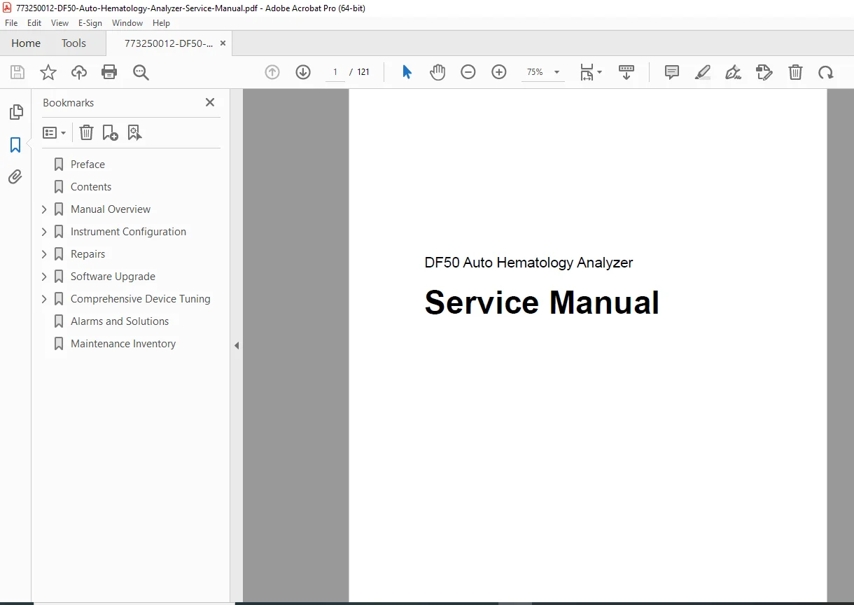
- Manual Title: Auto Hematology Analyzer Service Manual
- Model Covered: DF50
- Manufacturer: Shenzhen Dymind Biotechnology Co., Ltd. (DYMIND)
- Device Type: Automated Hematology Analyzer (CBC+DIFF)
- Application: Clinical Laboratory Diagnostics
- PDF Quality: High-resolution professional service documentation
- Total Pages: 121 pages
- Language: English
- File Format: Searchable PDF with detailed diagrams, schematics, and photographs
- Producer: Microsoft Office Word 2007
Special Features:
Complete Hydraulics Documentation: 38 pages of detailed hydraulics diagrams showing every valve, pump, syringe, bath, and tubing connection with comprehensive troubleshooting for all fluid-path problems.
Optical System Service: Full laser-based flow cytometry system documentation including fine-tuning procedures, alignment specifications, and component replacement instructions for maintaining optimal optical performance.
Step-by-Step Component Replacement: Every major assembly replacement documented with photographs, connector identification, mounting hardware specifications, and post-installation verification procedures.
Software Upgrade Procedures: Complete instructions for firmware updates, configuration backup/restore, and touch screen calibration ensuring service technicians can maintain current software.
Comprehensive Calibration Procedures: Detailed multi-point calibration instructions for all measurement parameters (WBC, RBC, PLT, HGB) in both whole-blood and predilute modes with acceptance criteria.
Complete Alarm Code Reference: All error codes documented with specific troubleshooting procedures, probable causes, and verified repair solutions, eliminating guesswork during service calls.
Safety-First Documentation: Extensive biohazard safety procedures, ESD protection protocols, electrical safety warnings, and PPE requirements protecting both technician and equipment.
Maintenance Inventory: Complete parts list with part numbers enabling efficient spare parts management and inventory planning for service departments.
Why This Manual is Essential for Biomedical Service:
This service manual is the complete authoritative resource for anyone maintaining Dymind DF50 hematology analyzers in clinical laboratories. Whether you’re a hospital biomedical equipment technician (BMET), a third-party service provider, or a clinical engineer responsible for laboratory equipment uptime, this manual provides the manufacturer-approved technical documentation required for professional-quality service and regulatory compliance.
Download immediately and gain instant access to 121 pages of factory-authorized service procedures, complete hydraulics and optical system schematics, component-level troubleshooting, calibration procedures, and alarm code solutions that will reduce analyzer downtime, improve service efficiency, and ensure accurate hematology results for patient care. Master the DF50’s complex hydraulics, optical, and electronic systems with this comprehensive technical reference!