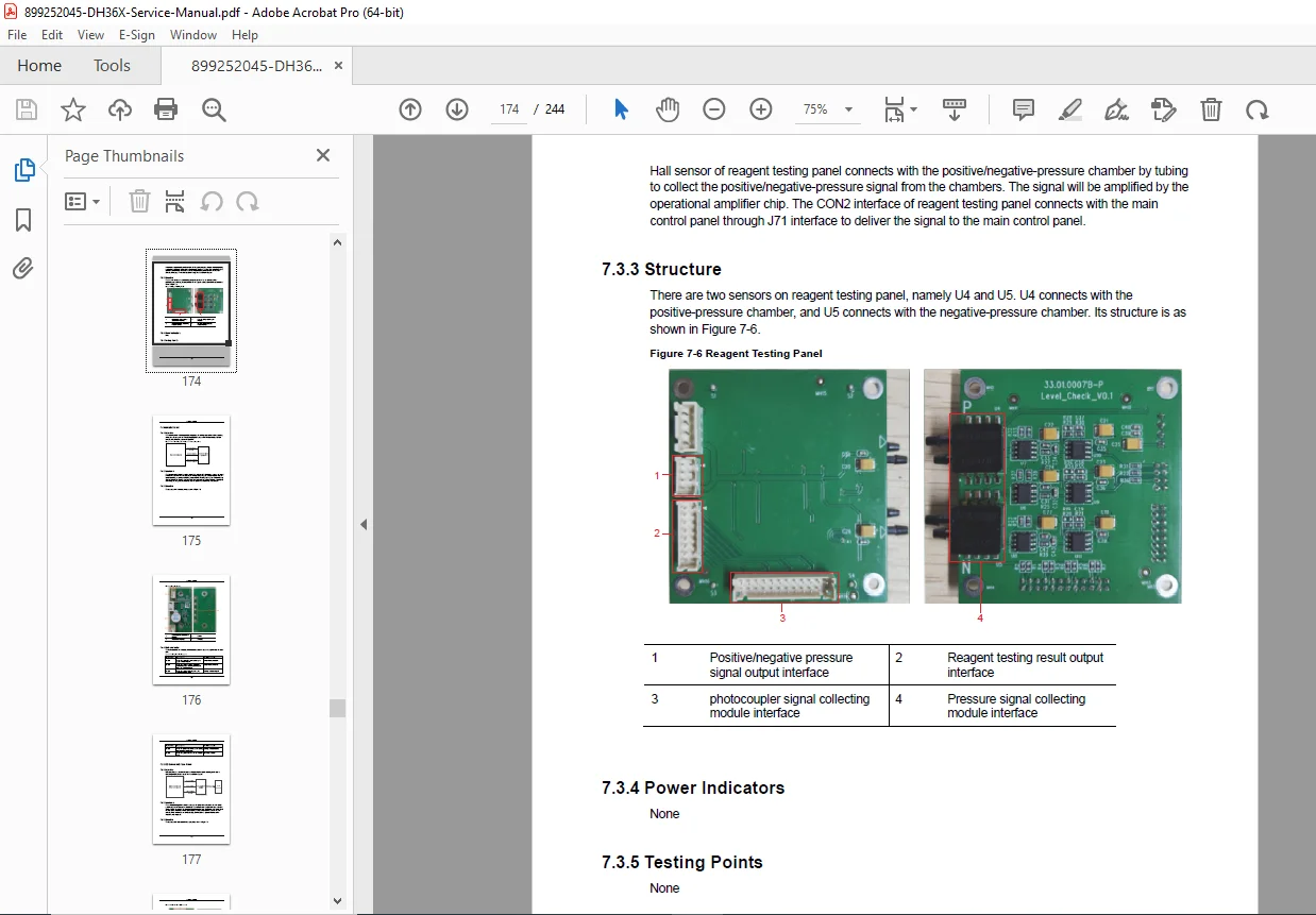
Dymind DH36X Hematology Analyzer Service Manual PDF
Original price was: $85.00.$17.95Current price is: $17.95.
Download the Dymind DH36X auto hematology analyzer service manual PDF for detailed repair, troubleshooting, and maintenance. Covers Dymind DH36X fluidics system diagram, DH36X hardware board replacement, Dymind DH36X software upgrade guide, DH36X mechanical disassembly procedures, error codes and troubleshooting for DH36X analyzer, and working principles. 244 pages with diagrams, sequences, and safety info for DH36X, DH33X, DH31X models
Description
Dymind DH36X Hematology Analyzer Service Manual PDF DOWNLOAD
Description
The Dymind DH36X Hematology Analyzer Service Manual PDF is a complete technical resource for servicing the DH36X, DH33X, and DH31X auto hematology analyzers from Shenzhen Dymind Biotechnology Co., Ltd. This manual details analyzer specifications, including dimensions, performance indices for parameters like WBC, RBC, PLT, HGB, and CRP, environmental conditions, and functions. It explains working principles using electrical impedance for WBC/RBC/PLT measurement, colorimetric method for HGB, and immune nephelometry for CRP. The software system section covers interface navigation, user access control, Dymind DH36X software upgrade guide with preparations and abnormality handling, and LIS connection procedures.
The mechanical system chapter provides layouts of front, side, back, and internal views, along with DH36X mechanical disassembly procedures for panels, pumps, valves, pressure chambers, syringes, baths, sensors, heating devices, display screens, and power supplies. The fluidics system includes sample dilution processes for whole-blood and predilute modes, channel descriptions for WBC/HGB, RBC/PLT, CRP, sampling, power, and waste, plus Dymind DH36X fluidics system diagram in Appendix C. Fluidics sequences for counting modes and troubleshooting for valve/pump failures, clogs, overflows, pressure issues, leaks, and aperture voltage abnormalities are detailed.
Hardware system overviews main control, reagent testing, indicator, LCD interface, CRP laser driver, sealing, and refrigerating panels with structures, interfaces, indicators, testing points, and error codes and troubleshooting for DH36X analyzer. Management of interface errors addresses reagent, pressure, syringe, temperature, status, power, system, clogging, and motor issues with specific fixes. Maintenance includes status check-outs, plans with lists and steps, and consumable parts. Appendices list error information, fluidics components with tube/connector types, and the analyzer’s fluidics diagram.
This high-quality PDF naturally incorporates DH36X hardware board replacement instructions and other keywords for effective use in laboratory equipment repairs.
Table of Contents:
- Preface (i)
- 1 Manual Overview (1)
- 1.1 Overview (1)
- 1.2 Who Should Read This Manual (1)
- 1.3 Symbols and Their Meanings (1)
- 1.4 Safety Instructions (4)
- 2 Analyzer Specifications (6)
- 2.1 Overview (6)
- 2.2 Specifications (6)
- 2.2.1 Dimensions and Weight (6)
- 2.2.2 Sample Type (7)
- 2.2.3 Sample Dosage (7)
- 2.2.4 Performance Index (7)
- 2.2.5 Noise (9)
- 2.2.6 Rated Parameters (9)
- 2.2.7 Requiring Time for Startup/Shutdown and Replacing Reagents (9)
- 2.2.8 Environmental Conditions (10)
- 2.2.9 Storage Temperature and Expiration Date of the Reagent (10)
- 2.2.10 Functions of the Analyzer (10)
- 2.2.11 Status Indicator (11)
- 3 Working Principles (12)
- 3.1 Overview (12)
- 3.2 WBC/RBC/PLT Measurement (12)
- 3.2.1 Electrical Impedance Method (12)
- 3.2.2 Derivation of WBC-related Parameters (13)
- 3.2.3 RBC (14)
- 3.2.4 PLT (15)
- 3.3 HGB Measurement (15)
- 3.3.1 Colorimetric Method (15)
- 3.3.2 HGB (15)
- 3.4 CRP Measurement (16)
- 3.4.1 Immune Nephelometry Principle (16)
- 3.4.2 CRP (16)
- 4 Software System (17)
- 4.1 Overview (17)
- 4.2 Interface Introduction (17)
- 4.3 User Access Control (19)
- 4.4 Software Upgrade (28)
- 4.4.1 Preparations (28)
- 4.4.2 Upgrading Steps (29)
- 4.4.3 Description of Abnormalities (32)
- 4.5 LIS Connection (34)
- 4.5.1 Installing LIS Workstation (34)
- 4.5.2 Setting Host Communication (34)
- 4.5.3 Connecting the Analyzer with LIS (35)
- 4.5.4 Description of Abnormalities (37)
- 5 Mechanical System (39)
- 5.1 Overview (39)
- 5.2 Introduction to the Exterior and Layout (39)
- 5.2.1 Front View (39)
- 5.2.2 Side View (40)
- 5.2.3 Back View (41)
- 5.2.4 Layout of the Front (42)
- 5.2.5 Layout of the Back (43)
- 5.2.6 Layout of the Right Side (44)
- 5.2.7 Layout of the Left Side (45)
- 5.3 Preparations Before Maintenance (45)
- 5.3.1 Removing the Back Panel (46)
- 5.3.2 Opening the Right-side Door (47)
- 5.3.3 Removing the Top Panel (48)
- 5.3.4 Removing the Left-side Panel (49)
- 5.3.5 Removing the Front Panel (50)
- 5.4 Replacement of the Pump and Valve Assemblies (51)
- 5.4.1 Replacing the Liquid Pump Module (51)
- 5.4.2 Replacing the Air Pump Assembly (53)
- 5.4.3 Replacing the Valve Assembly (56)
- 5.5 Replacement of the Pressure Chamber Assembly (57)
- 5.5.1 Replacing the Negative-pressure Chamber Assembly (57)
- 5.5.2 Replacing the Positive-pressure Chamber Assembly (59)
- 5.6 Replacement of Panels (62)
- 5.6.1 Replacing the Main Control Panel (63)
- 5.6.2 Replacing the Reagent Testing Panel (64)
- 5.6.3 Replacing CRP Laser Driver Panel (66)
- 5.6.4 Replacing Reagent Refrigerating Panel (67)
- 5.6.5 Replacing Indicator Panel (68)
- 5.6.6 Replacing Reagent Sealing Panel (70)
- 5.7 Replacement of the Sampling Assembly (71)
- 5.7.1 Replacing the Sample Probe (71)
- 5.7.2 Replacing the Photocoupler (74)
- 5.7.3 Replacing the Sampling Assembly in X- or Y-direction (76)
- 5.8 Replacement of Syringe Assembly (78)
- 5.8.1 Replacing the Syringe (78)
- 5.8.2 Replacing the Motor (80)
- 5.9 Replacement of WBC/RBC Bath (83)
- 5.9.1 Replacing WBC Bath Assembly (83)
- 5.9.2 Replacing RBC Bath Assembly (87)
- 5.10 Replacement of CRP Reaction Bath Assembly (90)
- 5.10.1 Replacing the Whole Assembly (90)
- 5.10.2 Replacing CRP Laser Assembly (91)
- 5.11 Replacement of the Sensors (93)
- 5.11.1 Replacing Ambient Temperature Sensor (93)
- 5.11.2 Replacing the Lyse Reagent Sensor (94)
- 5.12 Replacement of the Diluent Heating Device (95)
- 5.13 Replacement of the Display Screen Assembly (99)
- 5.14 Replacement of the Power Supply Assembly (100)
- 6 Fluidics System (103)
- 6.1 Overview (103)
- 6.2 Sample Dilution Procedure (103)
- 6.2.1 Whole-blood CBC Mode (103)
- 6.2.2 Whole-blood CBC+CRP Mode (104)
- 6.2.3 Predilute CBC Mode (105)
- 6.3 Fluidics Channel Description (105)
- 6.3.1 WBC/HGB Measurement Channel (105)
- 6.3.2 RBC/PLT Measurement Module (107)
- 6.3.3 CRP Measurement Channel (108)
- 6.3.4 Sampling and Blood Dispensing Channel (109)
- 6.3.5 Power Channel (110)
- 6.3.6 Waste Discharge Channel (110)
- 6.4 Fluidics Sequence (111)
- 6.4.1 Sequence of Whole-Blood Mode Counting (111)
- 6.4.2 Sequence of Prediluted Mode Counting (129)
- 6.5 Troubleshooting (129)
- 6.5.1 Valve Failure (129)
- 6.5.2 Liquid Pump Failure (130)
- 6.5.3 WBC Bath Clogging (132)
- 6.5.4 RBC Bath Clogging (134)
- 6.5.5 WBC Bath Overflowing (136)
- 6.5.6 RBC Bath Overflowing (138)
- 6.5.7 CRP Bath Overflowing (138)
- 6.5.8 Failed to Build Positive Pressure (139)
- 6.5.9 Failed to Build Negative Pressure (140)
- 6.5.10 Swab Leakage (142)
- 6.5.11 Abnormal Aperture Voltage (143)
- 7 Hardware System (145)
- 7.1 Overview (145)
- 7.2 Main Control Panel (145)
- 7.2.1 Overview (145)
- 7.2.2 Functions (146)
- 7.2.3 Structure (147)
- 7.2.4 Interface (149)
- 7.2.5 Power Indicator Light (152)
- 7.2.6 Testing Points (154)
- 7.3 Reagent Testing Panel (157)
- 7.3.1 Overview (157)
- 7.3.2 Functions (157)
- 7.3.3 Structure (158)
- 7.3.4 Power Indicators (158)
- 7.3.5 Testing Points (158)
- 7.4 Indicator Panel (159)
- 7.4.1 Overview (159)
- 7.4.2 Functions (159)
- 7.4.3 Structure (159)
- 7.4.4 Status Indicator (160)
- 7.5 LCD Screen Interface Panel (161)
- 7.5.1 Overview (161)
- 7.5.2 Functions (161)
- 7.5.3 Structure (161)
- 7.5.4 Testing Points (162)
- 7.6 CRP Laser Driver Panel (163)
- 7.6.1 Overview (163)
- 7.6.2 Functions (164)
- 7.6.3 Structure (164)
- 7.6.4 Indicators (164)
- 7.6.5 Testing Points (165)
- 7.7 Reagent Sealing Panel (165)
- 7.7.1 Overview (165)
- 7.7.2 Functions (166)
- 7.7.3 Structure (166)
- 7.7.4 Indicators (166)
- 7.8 Reagent Refrigerating Panel (167)
- 7.8.1 Overview (167)
- 7.8.2 Functions (167)
- 7.8.3 Structure (168)
- 7.8.4 Power Supply Indicators (168)
- 7.9 Troubleshooting (169)
- 7.9.1 Main Control Panel (169)
- 7.9.2 Reagent Testing Panel (174)
- 7.9.3 Indicator Panel (175)
- 7.9.4 CRP Laser Driver Panel (175)
- 7.9.5 LCD Switching Panel (176)
- 7.9.6 Reagent Testing Panel (176)
- 7.9.7 Reagent Sealing Panel (177)
- 8 Management of Interface Errors (178)
- 8.1 Overview (178)
- 8.2 Reagent Error (179)
- 8.2.1 Reagent Expired (179)
- 8.2.2 Reagent Not Enough (179)
- 8.2.3 Reagent Not Replaced (180)
- 8.2.4 Reagent Running Out (180)
- 8.2.5 Reagent Sensor Errors (181)
- 8.3 Pressure Errors (182)
- 8.3.1 Pressure of Positive-pressure Chamber (182)
- 8.3.2 Pressure of Negative-pressure Chamber (184)
- 8.4 Syringe Errors (186)
- 8.4.1 Sample Syringe (187)
- 8.4.2 CRP Diluent Syringe (188)
- 8.4.3 Lyse Syringe (190)
- 8.5 Temperature Errors (191)
- 8.6 Status Error (193)
- 8.7 Power Supply Errors (193)
- 8.8 System Errors (194)
- 8.9 Clogging Errors (196)
- 8.10 Motor Errors (196)
- 8.10.1 Horizontal Sampling Motor (197)
- 8.10.2 Vertical Sampling Motor (198)
- 8.10.3 Sampling Assembly Horizontal Motor (200)
- 9 Maintenance (202)
- 9.1 Overview (202)
- 9.2 Status Check-out (202)
- 9.3 Maintenance Plan (203)
- 9.3.1 Maintenance List (203)
- 9.3.2 Maintenance Steps (204)
- 9.4 List of Consumable Parts (212)
- 10 Lists of Maintenance Parts (213)
- 10.1 Components (213)
- 10.2 Panels (214)
- 10.3 Valves (215)
- 10.4 Wires (215)
- 10.5 Tubes (216)
- Appendix A List of Error Information (217)
- Appendix B List of Fluidics Components (219)
- B.1 Fluidics Components (219)
- B.2 Tube Types (222)
- B.3 Connector Types (224)
- Appendix C Fluidics Diagram of the Analyzer (227)
File Details:
- Manual Name: Auto Hematology Analyzer Service Manual
- Models Covered: DH36X, DH33X, DH31X
- Year: 2021
- Manual PDF Quality: High-quality with clear text, tables, diagrams, and photos
- No. of Pages: 244