Epson DFX-8500 Dot Matrix Printer Service Manual Repair Guide PDF
Original price was: $95.00.$18.95Current price is: $18.95.
Complete factory service manual for the Epson DFX-8500 18-pin serial impact dot matrix printer. This comprehensive 237-page technical manual covers product specifications, theory of operation, complete disassembly procedures, mechanical adjustments, troubleshooting, maintenance, and repair procedures. Essential resource for technicians servicing high-volume business printers. Includes detailed circuit diagrams, exploded parts views, complete parts lists, and step-by-step repair instructions.
Description
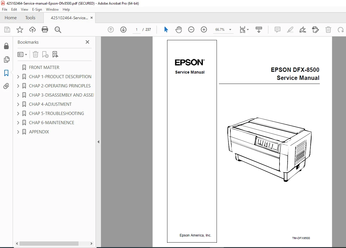
Epson DFX-8500 Dot Matrix Printer Service Manual Repair Guide – PDF DOWNLOAD
DESCRIPTION
Complete Service Manual for Epson DFX-8500 Dot Matrix Printer
This official Epson DFX-8500 service manual is the authoritative factory documentation for servicing and repairing the DFX-8500 high-speed dot matrix printer. This essential dot matrix printer repair guide provides professional technicians with comprehensive technical information covering every aspect of printer maintenance, diagnostics, component replacement, and mechanical adjustments for this business-class printing system.
📋 File Details
- Manual Name: EPSON DFX-8500 Service Manual
- Printer Model: Epson DFX-8500 (18-pin Serial Impact Dot Matrix)
- Manufacturer: Epson America, Inc.
- Manual Number: TM-DFX8500
- Year: 1998
- Manual Quality: Factory Original – Excellent Quality PDF
- Total Pages: 237 Pages
- File Size: 5.9 MB
📖 Complete Table of Contents
Chapter 1: Product Description
1.1 Features
- Advanced Paper Handling Systems
- Paper Jam Detection
- Paper Width Detection
- Front and Rear Two-Way Push Tractors
- Optional Pull Tractor Compatibility
- Automatic Paper Back-Out and Loading
- Automatic Platen Gap Adjustment
- Automatic Tear-Off Positioning
- Paper Memory Function
- Automatic Paper Path Switching
- Auto-Cut Mode for Optional Perforation Cutter
- Bi-Directional Parallel Interface (IEEE-1284 Nibble)
- RS-232C Serial Interface Standard
- EPSON ESC/P and IBM/Lexmark 2381 Plus Emulation
- 35 Character Tables in NLSP Version
1.2 Specifications
- Printing Specifications: Speed, resolution, character sets, fonts
- Paper Feeding Specifications: Tractor feed, friction feed capabilities
- Electrical Specifications: Power requirements, current ratings
- Environmental Specifications: Operating conditions, storage requirements
- Reliability: MTBF ratings
- Safety Approvals: Compliance certifications
- CE Marking: European compliance
- Acoustic Noise: Sound level specifications
- Ribbon Cartridge: Compatible ribbon specifications
- Physical Specifications: Dimensions and weight
- Printable Area: Maximum print dimensions
- Paper and Media:
- Continuous Paper (Single-Sheet and Multi-Sheet Forms)
- Labels Specifications
- Continuous Forms with Labels
- Overlapping Multi-Sheet Forms
- Perforations Requirements
- Media Handling Notes
1.3 Interfaces
- Parallel Interface (Forward Channel) – IEEE-1284
- Parallel Interface (Reverse Channel) – Bi-directional communication
- Serial Interface – RS-232C specifications
- Optional Interface Support
- Interface Selection Methods
- Timeout Prevention Techniques
1.4 Operating Instructions
- Control Panel: Complete panel layout and functions
- Buttons: Function descriptions
- Indicators: LED and status displays
- Errors and Buzzers: Error code reference
- DIP Switch Settings: Configuration options
- Control Panel Functions:
- Normal Operation Procedures
- Advanced Control Panel Functions
- Automatic Detection Functions
- Paper Memory Functions
- Initializations:
- Hardware Initialization
- Software Initialization
- Panel Initialization
1.5 Main Components
- M-3I60 Printer Mechanism Overview
- C204 Main Board Description
- C204 DRV Board Details
- C204 DRV-B Board Specifications
- C204 SUB Board Functions
- C204 PSB/PSE Board Information
- Control Panel Components
- Housing Assembly
Chapter 2: Theory of Operation
2.1 Printer Mechanism Operation
- Printhead Operation and Control
- Carriage Movement System
- Paper Feed Mechanisms
- Platen Gap Control (0.35 to 0.84 mm range)
- Ribbon Feed System
2.2 Power Supply Operation
- Voltage Specifications (4.75 – 5.25 VDC)
- Current Distribution and Ratings
- Protection Circuits
- Fuse Specifications (6.3 A / 250 VAC)
- Power Supply Regulation
2.3 Control Circuits
- Microprocessor Control Systems
- Motor Drive Circuits
- Sensor Interface Circuits
- Communication Interface Logic
- Error Detection Circuitry
Chapter 3: Disassembly and Assembly
3.1 Disassembly Overview
- Safety Precautions
- Required Tools
- Disassembly Sequence
- Component Handling Guidelines
3.2 Component Removal Procedures
3.2.1-3.2.3 Housing Disassembly:
- Top Cover Removal
- Left, Right, and Front Covers Removal
- Fuse Replacement Procedures
- Front Panel Removal
- Upper Case Removal
3.2.4 Circuit Board Removal:
- Bottom Panel Removal
- Fan and C204 Power Supply Board Removal
- C204 SUB Board Removal
- C204 DRV-B and C204 DRV Board Removal
- C204 Main Board Removal
- AC Inlet Removal
- C204 PNL Board Removal
3.2.5 Printer Mechanism Disassembly
3.2.6 Detailed Component Removal:
- Fan Removal
- Ribbon Feed Change Lever Unit Removal
- Tractor Select Lever Disassembly
- Ribbon Jam Sensor Removal
- Connector Junction Board and FPC Board Removal
- Platen Gap (PG) Sensor and PG Motor Removal
- Plunger and Paper Bail Removal
- Upper Paper Guide and Top PE Sensor Removal
- Tension Roller Shaft Removal
- Additional Mechanical Components
Assembly Instructions:
- Reverse disassembly procedures with critical notes
- Lubrication requirements during reassembly
- Post-assembly adjustments required
Chapter 4: Adjustments
Complete adjustment procedures required after component replacement or repair:
- Flight Time Adjustment: Printhead timing calibration
- Platen Gap Adjustment: Critical spacing calibration (0.35 to 0.84 mm)
- Tractor Wire Spring Adjustment: Front and rear tractors
- Carriage Mechanism Adjustments: Multiple alignment procedures
- Platen Roller Adjustments: Positioning and alignment
- Paper Feed Adjustments: Tractor and friction feed calibration
- Sensor Alignments: Position and detection calibration
- Printhead Alignment: Print quality adjustments
Required Tools for Adjustments Listed
Chapter 5: Troubleshooting
Comprehensive problem diagnosis and solutions:
- Symptom-Based Troubleshooting Charts
- Error Code Reference and Resolution
- Print Quality Problems
- Paper Feed Issues
- Electrical Failures
- Mechanical Malfunctions
- Control Panel Error Messages
- Communication Interface Problems
- Cross-Reference to Repair Chapters 3 & 4
Chapter 6: Maintenance
Preventive maintenance procedures:
- Regular Cleaning Schedules
- Lubrication Points and Procedures (Oil 0-2 specification)
- Component Inspection Intervals
- Routine Adjustments
- Consumables Replacement
- Preventive Maintenance Checklists
Appendix A: Parts and Reference
A.1-A.4 Complete Parts Lists:
- Part Numbers
- Part Descriptions
- Replacement Part Specifications
- Cross-Reference Tables
A.5 Exploded Diagrams:
- Figure A-11: Exploded Diagrams (1)
- Figure A-12: Exploded Diagrams (2)
- Figure A-13: Exploded Diagrams (3)
- Figure A-14: Exploded Diagrams (4)
- Figure A-15: Exploded Diagrams (5)
- Figure A-16: Exploded Diagrams (6)
- Figure A-17: Exploded Diagrams (7)
- Figure A-18: Exploded Diagrams (8)
A.6 Circuit Diagrams:
- C204 Main Board Schematics
- C204 DRV Board Schematics
- C204 DRV-B Board Schematics
- C204 PSB Board Schematics
- C204 PSE Board Schematics
- Complete Wiring Diagrams
💡 What Makes This Manual Essential
✅ Official Factory Documentation – Direct from Epson America, ensuring accuracy ✅ Complete Disassembly Procedures – Step-by-step component removal and installation ✅ Detailed Adjustment Instructions – Critical calibration procedures for quality printing ✅ Circuit Diagrams Included – Complete electrical schematics for all boards ✅ Exploded Parts Views – 8 detailed exploded diagrams for visual reference ✅ Comprehensive Parts Lists – Part numbers for easy ordering ✅ Troubleshooting Charts – Symptom-based problem diagnosis ✅ Theory of Operation – Understanding system functionality for better repairs
🔧 Who Needs This Manual
- Printer Repair Technicians servicing dot matrix printers
- IT Support Professionals maintaining office printing equipment
- Business Equipment Service Centers specializing in Epson products
- Independent Repair Shops working with impact printers
- Corporate IT Departments managing printer fleets
- Print Shop Operators maintaining high-volume printing equipment
- Technical Training Programs teaching printer repair and maintenance
⚙️ Technical Coverage Includes
- Print Mechanism: 18-pin printhead, carriage system, ribbon feed mechanism
- Paper Handling: Push/pull tractors, friction feed, paper detection sensors
- Control Systems: Microprocessor control, motor drivers, sensor interfaces
- Power Supply: Multi-voltage regulation, protection circuits, fuse replacement
- Circuit Boards: Main board, DRV boards, SUB board, PSB/PSE boards, PNL board
- Interface Systems: IEEE-1284 parallel, RS-232C serial, optional interfaces
- Mechanical Systems: Platen gap adjustment, carriage movement, paper path control
- Sensors: Paper jam detection, paper width detection, ribbon jam detection
🎯 Key Service Procedures Covered
- Complete printer disassembly and reassembly
- Circuit board removal and installation
- Printhead replacement and alignment
- Platen gap calibration (0.35-0.84mm precision)
- Tractor mechanism service and adjustment
- Ribbon feed system maintenance
- Paper sensor calibration
- Control panel diagnostics
- Power supply troubleshooting
- Interface configuration and testing
- Lubrication and cleaning procedures
- DIP switch configuration
🖨️ Epson DFX-8500 Applications
This high-speed dot matrix printer is used for:
- Multi-part forms printing
- Continuous form processing
- Invoice and statement printing
- High-volume business applications
- Shipping and logistics documentation
- Manufacturing and warehouse labels
- Retail back-office operations
- Financial document printing
📱 Instant Access – Download Now
Get immediate access to this essential Epson DFX-8500 service manual. Perfect for professional technicians who need comprehensive factory documentation for expert dot matrix printer service and repair. Download instantly and restore your Epson DFX-8500 printers to peak performance with confidence today!
Pricing Rationale:
- 237-page comprehensive technical manual
- Official Epson factory documentation (high authority)
- Business-class printer (professional/commercial market)
- Complete with circuit diagrams and exploded views
- Detailed disassembly and adjustment procedures
- Specialized dot matrix printer knowledge required
- Comparable printer service manuals typically $30-$50
- Moderate-to-high complexity (electromechanical systems)
- Essential for professional printer repair services