Epson EPL-C8000 Service Manual – PDF DOWNLOAD
$30.95
Epson EPL-C8000 Service Manual – PDF DOWNLOAD
Description
Epson EPL-C8000 Service Manual – PDF DOWNLOAD
FILE DETAILS:
Epson EPL-C8000 Service Manual – PDF DOWNLOAD
Language :English
Pages :545
Downloadable : Yes
File Type : PDF
IMAGES PREVIEW OF THE MANUAL:
DESCRIPTION:
Epson EPL-C8000 Service Manual – PDF DOWNLOAD
About this manual
This manual describes basic functions, theory of electrical and mechanical operations, maintenance and repair procedures of EPL-C8000. The
instructions and procedures included herein are intended for the experienced repair technicians, and attention should be given to the precautions on
the preceding page.
Safety Information
To prevent accidents during a maintenance procedure, strictly observe the Warnings and Cautions. Do not do anything that is dangerous or not within the scope of this document. Do not do anything that is dangerous even if not specifically described in this manual. In addition to the descriptions below and those given in this manual, there are many situations and circumstances that are dangerous. Be aware of these when you are working with the printer.
TABLE OF CONTENTS:
Epson EPL-C8000 Service Manual – PDF DOWNLOAD
EPL-C8000 SERVICE MANUAL (Rev B) 1
PRODUCT DESCRIPTIONS 15
11 Features 17
12 Specifications 19
121 Basic Specifications 19
122 Paper Specification 24
123 Reliability and Durability 27
124 Operating Environment (including options) 29
125 Environmental Conditions for Storage and Transportation 30
126 Electrical Specification 31
127 Process Specifications 32
128 Applicable Standards 32
129 Consumables and Options 33
1291 Toner cartridge 33
1292 DRUM CARTRIDGE 34
1293 Fuser Oil Roll 35
1294 Waste Toner Box 35
1210 Regularly Replaced Parts 35
1211 Exterior Dimensions 36
1212 Controller Specification 37
1213 Controller Board Jumper Settings 37
13 Interface Specifications 38
131 Parallel Interface Specification 39
132 Option Interface 41
14 Control Panel 42
141 Appearance and Descriptions 42
1411 LED Description 43
142 Button Functions 44
15 Service Functions 46
151 Hex dump Mode 46
152 EEPROM Initialization 46
153 Formatting the Flash ROM Module 46
154 Updating the Program ROM 46
155 ROM Module Copy 46
156 Panel Setting Initialization 47
157 Maintenance Mode 47
158 Error Recovery Operation 47
16 Panel Setting 48
161 Setting Methods 48
162 SelecType Setting Menu List 51
163 Details of Menus and Settings 55
OPERATING PRINCIPLES 59
21 Print Process 62
211 Print Process Overview 62
212 Print Process – Major Components 63
213 Print Process Description 64
2131 (1) Charge 64
2132 (2) Exposure 65
2133 (3) Development 66
2134 (4) First Transfer (Drum Æ Belt) 69
2135 (5) Cleaning (Drum) 70
2136 (6) Repeat (Forming a complete full-color toner image) 71
2137 (7) Second Transfer (Belt Æ Paper) 72
2138 (8) Detach 74
2139 (9) Cleaning (Belt) 74
21310 (10) Fusing 75
22 Print Data Flow 76
221 Data Flow 76
23 Driver Power Transmission Path 77
231 Process Motor Assembly 77
232 P/H Motor Assembly 78
233 Dispense Motor Assembly 79
234 Rotary Motor Assembly 79
235 Gear Layout 80
24 Paper Transportation 81
241 Paper Transportation Path (No Option) 81
25 Main Components 82
251 Paper Tray 83
252 Paper Feeder 84
253 Multi Sheet Inserter (MSI) 85
254 Paper Transportation 87
255 Xerographics I 89
256 Xerographics II 90
257 Development 92
258 IBT-I 94
259 IBT-II 95
2510 Fusing-I 96
2511 Fusing-II 98
2512 Paper Exit100
2513 Drives101
2514 Electrical103
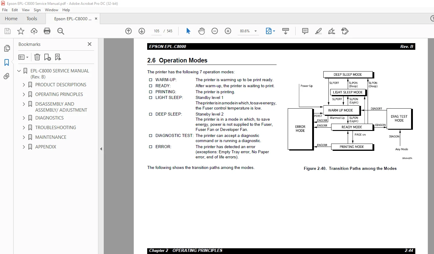
26 Operation Modes105
27 Controls106
271 Paper Size Control106
272 Paper Tray Selection Control107
273 OHP Side Detection Control108
274 ROS Control109
2741 Scanner Motor Rotation109
2742 Light Quantity Control109
275 Process Control110
2751 Electric Potential Control110
2752 Toner Density Control (PCDC)111
2753 Toner Density Control (ADC)112
2754 ADC Solenoid Operation113
2755 Process Sequence113
276 Xerographic Control114
2761 BCR/Erase Lamp Control114
2762 Drum Cartridge Replacement115
2763 Drum Cartridge End of Life Detection116
2764 Waste Toner Box Full Detection116
277 Developer Control117
2771 Home Position Detection117
2772 Toner Cartridge Detection Position118
2773 Toner Cartridge: Old/New Detection118
2774 Development Position118
2775 Development Control: Detection Methods119
278 IBT Control121
2781 First Transfer (Drum Æ Belt)121
2782 Second Transfer (Belt Æ Paper)122
2783 Discharging125
2784 Belt Cleaning125
279 1-UP/2-UP Control128
2710 Fuser Control129
27101 Fuser Control Method129
27102 Warm-up Control129
27103 Mode Control: READY, LIGHT SLEEP, DEEP SLEEP130
27104 Printing Mode Control130
27105 Not Ready State Detection During Printing130
27106 Oil Roll Control131
27107 Fuser Fan Control133
27108 Detection Controls in Fuser133
28 Controller Operating Principles137
DISASSEMBLY AND ASSEMBLY/ ADJUSTMENT140
31 Overview143
311 Precautions for disassembly, assembly and adjustment143
312 Tools144
313 Items to check after assembly144
32 Disassembly/Assembly Procedures145
321 Exterior View and Part Names146
322 Removing/Replacing the Consumables147
323 Updating the Program ROM147
3231 Updating the ROM using a standard parallel interface148
3232 Updating by copying from the FLASH ROM module149
3233 Formatting the FLASH ROM Module150
3234 Formatting the FLASH ROM Module151
324 Cover152
3241 FRONT COVER ASSEMBLY Removal (PL111)152
3242 FRONT LOWER COVER Removal (PL115)152
3243 TOP COVER ASSEMBLY Removal (PL1120)153
3244 INNER COVER ASSEMBLY Removal (PL1110)154
3245 REAR COVER ASSEMBLY Removal (PL1130)155
3246 FILTER ASSEMBLY Removal (PL1132)156
3247 LEFT LOWER COVER Removal (PL1140)156
3248 RIGHT COVER ASSEMBLY Removal (PL1150)157
3249 OPERATION PANEL Removal (PL1160)157
325 Paper Tray158
3251 UNIVERSAL TRAY Removal (PL211)158
3252 FRONT SNUBBER Removal (PL229)158
3253 END GUIDE (PL2216), SECTOR GEAR (PL2217) Removal159
326 Paper Feeder161
3261 TURN IN CHUTE Removal (PL3118)161
3262 TURN ROLL ASSEMBLY Removal (PL3111)162
3263 FEED ROLL Removal (PL313)163
3264 FEED SOLENOID Removal (PL319)164
3265 FEED ROLL ASSEMBLY Removal (PL311)165
3266 SIZE SWITCH ASSEMBLY Removal (PL319)166
3267 TRAY N/P SENSOR ASSEMBLY Removal (PL3130)167
3268 LOW PAPER SENSOR Removal (PL3135)168
3269 TRAY NO PAPER SENSOR Removal (PL3132)168
327 Multi Sheet Inserter169
3271 MSI TRAY ASSEMBLY Removal (PL4110)169
3272 MSI ASSEMBLY Removal (PL411)170
3273 MSI FRONT COVER Removal (PL413)171
3274 MSI REAR COVER Removal (PL414)171
3275 MSI TOP COVER ASSEMBLY Removal (PL424)172
3276 MSI EDGE SENSOR Removal (PL426)173
3277 MSI SHORT N/P SENSOR Removal (PL427)173
3278 PICK UP ROLL Removal (PL4211)174
3279 RETARD PAD ASSEMBLY Removal (PL433)175
32710 PICK UP SOLENOID Removal (PL4221)176
32711 MSI CLUTCH Removal (PL4226)177
32712 MSI ROLL ASSEMBLY Removal (PL429)178
32713 MSI BOTTOM ASSEMBLY Removal (PL439)179
32714 MSI LONG N/P SENSOR Removal (PL4316)180
328 Paper Transportation181
3281 MAIN P/H ASSEMBLY Removal (PL511)181
3282 PRE-REGI CHUTE ASSEMBLY Removal (PL515)182
3283 P/H TURN CHUTE ASSEMBLY Removal (PL514)183
3284 REGI CHUTE ASSEMBLY Removal (PL516)184
3285 PRE-REGI CLUTCH Removal (PL528)185
3286 PRE-REGI ROLL ASSEMBLY Removal (PL524)186
3287 REGI CLUTCH Removal (PL5215)187
3288 REGI BRAKE CLUTCH Removal (PL5220)188
3289 REGI METAL ROLL Removal (PL5216)189
32810 REGI RUBBER ROLL Removal (PL5224)190
32811 REGI SENSOR Removal (PL5228)191
32812 FRONT OHP SENSOR Removal (PL5231)192
32813 REAR OHP SENSOR Removal (PL5232)193
329 Xerographics194
3291 DRUM CARTRIDGE Removal (PL6110)194
3292 WASTE TONER BOX Removal (PL6112)194
3293 ROS ASSEMBLY Removal (PL611)195
3294 ADC SENSOR ASSEMBLY Removal (PL6120)196
3295 XL RAIL ASSEMBLY Removal (PL6140)197
3296 WASTE TONER SENSOR Removal (PL6142)198
3297 TONER BOX SENSOR Removal (PL6143)198
3298 ERASE LAMP ASSEMBLY Removal (PL6130)199
3210 Development200
32101 Toner Cartridge Removal (PL711 ~ PL714)200
32102 Developer Assembly Removal (PL7110, PL7120, PL7130, PL7140)201
32103 Developer Removal (PL7113, PL7123, PL7133, PL7143)202
32104 ROTARY SENSOR Removal (PL7222)203
32105 ROTARY FRAME ASSEMBLY Removal (PL722)204
32106 CARTRIDGE SENSOR Removal (PL7226)206
32107 USED CART SENSOR Removal (PL7230)207
3211 IBT208
32111 TENSION LEVER Removal (PL814)208
32112 TRANSFER ASSEMBLY Removal (PL813)209
32113 BTR CAM SOLENOID Removal (PL8115)211
32114 BELT CLEANER ASSEMBLY Removal (PL8130)212
32115 2ND BTR ASSEMBLY Removal (PL8120)213
32116 2ND BTR CAM ASSEMBLY Removal (PL8110)214
32117 AUGER HIGH ASSEMBLY Removal (PL8140)215
32118 IBT BELT ASSEMBLY Removal (PL822)217
32119 TRO SENSOR Removal (PL8212)219
3212 Fusing220
32121 OIL ROLL ASSEMBLY Removal (PL9110)220
32122 FUSER ASSEMBLY Removal (PL911)220
32123 MAIN FUSER ASSEMBLY Removal (PL912)221
32124 FUSER UPPER ASSEMBLY Removal (PL9223)222
32125 H/R HEATER Removal (PL9220)223
32126 P/R HEATER Removal (PL9219)224
32127 LOWER GUIDE ASSEMBLY Removal (PL9226)225
32128 FUSER EXIT SENSOR Removal (PL9225)226
32129 UPPER GUIDE ASSEMBLY Removal (PL9232)226
321210 HEAT ROLL Removal (PL9212)227
321211 PRESSURE ROLL Removal (PL929)228
321212 TEMP SENSOR ASSEMBLY Removal (PL9224)229
321213 EXCHANGE CHUTE Removal (PL9310)230
321214 OIL CAM SOLENOID Removal (PL9321)231
321215 EXCHANGE SOLENOID Removal (PL9316)232
321216 OIL CAM ASSEMBLY Removal (PL9322)233
321217 CLEANER CAM SOLENOID Removal (PL9423)234
321218 CLEANER CAM ASSEMBLY Removal (PL9426)235
321219 EXIT-1 ROLL ASSEMBLY Removal (PL937)236
321220 CRU SWITCH ASSEMBLY Removal (PL9325)237
321221 FUSER IN SENSOR Removal (PL944)238
321222 FUSER CHUTE FAN Removal (PL9410)239
3213 Paper Exit240
32131 EXIT TRAY ASSEMBLY Removal (PL10110)240
32132 EXIT UPPER ASSEMBLY Removal (PL1012)240
32133 EXIT LOWER ASSEMBLY Removal (PL1011)241
32134 EXIT-2 ROLL ASSEMBLY Removal (PL1025)241
32135 EXIT-3 ROLL ASSEMBLY Removal (PL1027)242
32136 FUSER FAN Removal (PL10215)242
32137 TOP EXIT SENSOR Removal (PL10212)243
32138 EXIT CHUTE SWITCH Removal (PL10213)243
3214 Drive244
32141 P/H DRIVE ASSEMBLY Removal (PL1111)244
32142 P/H MOTOR ASSEMBLY Removal (PL1113)245
32143 ROTARY MOTOR PWB Removal (PL11121)245
32144 ROTARY MOTOR ASSEMBLY Removal (PL11120)246
32145 DISPENSE MOTOR ASSEMBLY Removal (PL11122)247
32146 FUSER DRIVE ASSEMBLY Removal (PL1112)248
32147 PROCESS MOTOR ASSEMBLY Removal (PL11112249
32148 PROCESS DRIVE ASSEMBLY Removal (PL11110)250
32149 DEVE CLUTCH ASSEMBLY Removal (PL11123)251
3215 Frame252
32151 DEVE TIE PLATE Removal (PL1214)252
3216 Electrical253
32161 LVPS Removal (PL1311)253
32162 HVPS Removal (PL1312)254
32163 TOP COVER SWITCH Removal (PL1313)254
32164 DEVE FAN Removal (PL1315)255
32165 MCU PWB Removal (PL1321)256
32166 COMMUNICATION ASSEMBLY Removal (PL1322)257
32167 FRONT COVER SWITCH R Removal (PL1323)258
32168 FRONT COVER SWITCH L Removal (PL1324)259
32169 ENVIRONMENT SENSOR Removal (PL1325)260
3217 Controller261
32171 CONTROLLER FAN Removal (PL 1412)262
32172 CONT CHASSIS ASSEMBLY Removal (PL 1411)262
33 Adjustment263
331 NIP Pressure Adjustment of the MAIN FUSER ASSEMBLY263
332 Deve Spacer Selection265
DIAGNOSTICS269
41 OVERVIEW271
411 Test print by MCU PWB271
412 Test Print Pattern272
42 Diagnostics by the Diagnostic Commander273
421 Introduction273
4211 Configuration273
4212 Diagnostic Commander274
4213 Diagnostic PWB274
422 Command/Status275
4221 Introduction275
4222 Data Format275
4223 Command/Status Categories276
423 Preparation276
4231 Personal Computer276
4232 Installing the Diagnostic Commander277
4233 Uninstalling the Diagnostic Commander277
4234 Connecting the Diagnostic Tool278
424 Diagnostic Commander: Operations279
4241 Starting the Diagnostic Commander279
4242 Setting Up the Communication279
4243 Sending/receiving commands/statuses280
4244 Automatically executing a command282
4245 [Service] tab283
4246 Displaying the log286
425 Life Counter Read/Write287
4251 Read287
4252 Write288
426 Executing Diagnostics289
4261 Diagnostic execution steps289
4262 Diagnostics functions289
4263 Test Print290
4264 Digital Input Test291
4265 Digital Input Test: Device codes292
4266 Digital Output Test296
4267 Digital Output Test: Device codes297
4268 Analog Input Test301
4269 Analog Input Test: Device codes302
42610 Analog Output Test303
42611 Analog Output Test: Device codes304
42612 EEPROM Read305
42613 EEPROM Write307
42614 EEPROM Initialize309
42615 NVM List310
427 Commands/Status List315
4271 Paper, Media & Output Control315
4272 Printing/Status Control317
4273 Parameter Control323
4274 Diagnostics control328
428 Error/Status Code330
429 Transfer MCU PWB Board NVRAM Engine Status to the New Board331
TROUBLESHOOTING332
51 Overview335
511 Troubleshooting Procedure335
512 Self-Diagnostic Function by LCD Message335
5121 Status Message337
5122 Error Message338
513 Warning Message343
514 Service-Call Error messages346
52 Level 1 FIP (Fault Isolation Procedure)348
53 Level 2 FIP (Fault Isolation Procedure)398
54 Print Quality Troubleshooting440
541 Print Quality Troubleshooting Entry Chart440
542 Print Quality FIP441
MAINTENANCE452
61 About On-Site Servicing454
611 On-site Service Flow455
612 Description of the On-site Service456
62 Maintenance Menu458
621 Entry to the Maintenance Menu458
622 Engine Status Sheet459
63 Consumable Replacement461
631 TONER CARTRIDGE Replacement462
632 OIL ROLL ASSEMBLY Replacement464
633 DRUM CARTRIDGE Replacement465
634 WASTE TONER BOX Replacement467
64 Regularly Replaced Part Replacement468
65 Installation468
APPENDIX471
A1 Parts List473
A 11 How to Use the Part List473
A 12 Part List Table474
A 13 Exploded Diagrams478
A 2 Wiring Diagrams492
A 21 P/ J Locations492
A22 Plug and Jack Location Table496
A 3 Wiring Diagrams and Signa lnformation500
A31 Master Wiring Diagram500
A 32 Wiring and Signal Description Between Components502
A 321 Organization502
A 33 Notations on the Diagrams for the Wiring and Signal Descriptions between Components504
A 3 31 Wiring Diagram – §1505
A 3 32 Wiring Diagram – §2507
A 3 33 Wiring Diagram – §3509
A 3 34 Wiring Diagram – §4511
A 3 35 Wiring Diagram – §5513
A 3 36 Wiring Diagram – §6515
A 3 37 Wiring Diagram – §7517
A 3 38 Wiring Diagram – §8519
A 3 39 Wiring Diagram – §9521
A 3 310 Wiring Diagram – §10523
A 3 311 Wiring Diagram – §11525
A 3 312 Wiring Diagram – §12527
A 3 313 Wiring Diagram – §13529
A4 Component Layout531
A 5 Circuit Diagrams533
A 6 Large Capacity Paper Unit540
A 61 Product Specifications540
A 6 11 Basic Specifications540
A614 Reliability and Durability541
A 63 Part List (Large Capacity Paper Unit)542
A 64 Exploded Diagrams543
A 65 Wiring Diagrams545
S.M 2/2/2025