Epson Stylus Photo 890 1280 1290 Service Maintenance Error Rescue Kit – PDF Download
Original price was: $24.95.$19.95Current price is: $19.95.
Epson Stylus Photo 890 1280 1290 Service Maintenance Error Rescue Kit
Description
Epson Stylus Photo 890 1280 1290 Service Maintenance Error Rescue Kit
FILE DETAILS:
Epson Stylus Photo 890 1280 1290 Service Maintenance Error Rescue Kit
FILE TYPE:PDF
DOWNLOADABLE:YES
MANUAL LANGUAGE:ENGLISH
PAGES:205
DESCRIPTION:
Epson Stylus Photo 890 1280 1290 Service Maintenance Error Rescue Kit
This manual describes basic functions, theory of electrical and mechanical operations, maintenance and repair procedures of EPSON Stylus PHOTO 890/1280/ 1290. The instructions and procedures included herein are intended for the experienced repair technicians, and attention should be given to the precautions on the preceding page. The chapters are organized as follows:
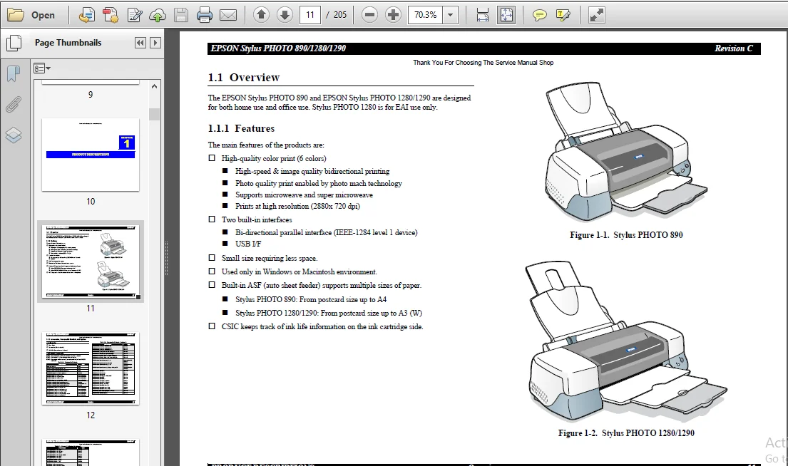
CHAPTER 1. PRODUCT DESCRIPTIONS
Provides a general overview and specifications of the product.
CHAPTER 2. OPERATING PRINCIPLES
Describes the theory of electrical and mechanical operations of the product.
CHAPTER 3. TROUBLESHOOTING
Provides the step-by-step procedures for troubleshooting.
CHAPTER 4. DISASSEMBLY AND ASSEMBLY
Describes the step-by-step procedures for disassembling and assembling the product.
CHAPTER 5. ADJUSTMENTS
Provides Epson-approved methods for adjustment.
CHAPTER 6. MAINTENANCE
Provides preventive maintenance procedures and the lists of Epson-approved lubricants and adhesives required for servicing the product.
APPENDIX
Provides the following additional information for reference:
• EEPROM Address Map
• Connector Pin Assignments
• Component Layout
• Exploded Diagrams
• Electrical Board Circuit Diagram
TABLE OF CONTENTS:
Epson Stylus Photo 890 1280 1290 Service Maintenance Error Rescue Kit
1 1 Overview 11
1 1 1 Features 11
1 1 2 Accessories, Consumable Products, and Options 12
1 2 Basic Specifications 14
1 2 1 Printing Specification 14
1 2 2 Control Code 14
1 2 3 Paper Feeding 14
1 2 4 Input Data Buffer 14
1 2 5 Paper Specifications 15
1 2 5 1 EPSON Special Media 15
1 2 6 Printing Area 17
1 2 6 1 Cut Sheet 17
1 2 6 2 Envelopes 18
1 2 7 Adjust Lever 18
1 2 8 Ink Cartridge 19
1 2 9 Electric Specification 20
1 2 10 Reliability 20
1 2 11 Environmental Condition 21
1 3 Interface 22
1 3 1 Parallel Interface (Forward Channel) 22
1 3 2 Parallel Interface (Reserve Channel) 25
1 3 3 USB Interface 26
1 3 4 Prevention of Data Transfer Time-out 27
1 3 5 Interface Selection 27
1 3 6 IEEE1284 4 Protocol 27
1 4 Operations 28
1 4 1 Buttons 28
1 4 2 Indicators 28
1 4 3 Panel Functions 28
1 4 4 Special Setting Mode 29
1 4 5 Printer Initialization 30
1 4 6 Initialization Value 30
1 5 Dimension 31
Chapter 2 OPERATING PRINCIPLES
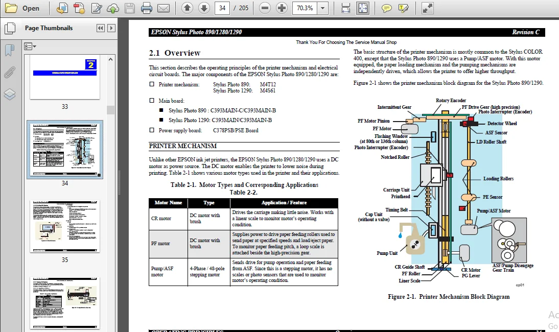
2 1 Overview 34
2 1 1 Printhead Mechanism 35
2 1 2 Carriage Mechanism 36
2 1 2 1 Carriage Motor (CR Motor) 36
2 1 2 2 Platen Gap (PG) /Parallelism Adjustment Mechanism 37
2 1 2 3 Carriage Home Position (HP) Detection 37
2 1 3 Paper Feeding Mechanism 37
2 1 3 1 CR Lock Mechanism 39
2 1 4 Paper Loading Mechanism 40
2 1 4 1 Drive Transmission to the ASF Unit 40
2 1 4 2 Paper Loading Operation 41
2 1 4 3 Pump Mechanism 42
2 1 4 4 Capping Mechanism 43
2 2 Electrical Circuit Operating Principles 44
2 2 1 C378PSB/PSE Board 44
2 2 1 1 Electrical Circuit 44
2 2 1 2 Protection Circuits 46
2 2 1 3 Power Supply Control Function 46
2 2 1 4 Energy Save Mode 46
2 2 2 C393MAIN Board Circuit Operation Principles 47
2 2 2 1 Printhead Driver Circuit 50
2 2 2 2 RTC (Real Time Clock)/ Reset/ EEPROM Circuit 51
2 2 2 3 Motor Driver Circuit 52
2 2 2 4 ASF/Pump Motor Driver Circuit 57
2 2 2 5 Sensor Circuit 58
Chapter 3 TROUBLESHOOTING
3 1 Overview 61
3 1 1 Self-Diagnostic Function 62
3 1 1 1 Troubleshooting with LED Error Indicators 62
3 1 1 2 Error Conditions 62
3 1 1 4 Remedies for the Paper Jam Error 67
3 1 1 5 Remedies for No Ink Cartridge Error/Ink Cartridge Problem 67
3 1 1 6 Remedies for Maintenance Request Error 68
3 1 1 7 Remedies for Fatal Error 69
3 1 2 Isolating the Faulty Part on the Power Supply Board 72
3 1 3 Isolating the Faulty Part according to the Phenomenon 72
Chapter 4 DISASSEMBLY AND ASSEMBLY
4 1 Overview 78
4 1 1 Precaution for Disassembling the Printer 78
4 1 2 Tools 79
4 1 3 Specifications for Screws 80
4 1 4 Service Checks After Repair 81
4 2 Disassembly Procedures 82
4 2 1 HOUSING Removal 83
4 2 2 Circuit Board Assembly Removal 84
4 2 3 Panel Unit Removal 86
4 2 4 Printhead Unit Removal 88
4 2 5 TRAY, ABSORBER ASSEMBLY Removal 89
4 2 6 Ink Unit Removal 91
4 2 7 MOTOR ASSEMBLY, CR Removal 94
4 2 8 MOTOR ASSEMBLY, ASF Removal 95
4 2 9 DE Unit Removal 96
4 2 10 ASF Unit Removal 99
4 2 10 1 SHAFT, ROLLER, LD Removal 101
4 2 10 2 ROLLER ASSEMBLY, LD, RIGHT/LEFT Removal 106
4 2 11 Carriage Unit Removal 107
4 2 12 BOARD ASSEMBLY, ENCODER Removal 109
4 2 13 ROLLER, PF Removal 110
4 2 13 1 SCALE, PF Installation 113
4 2 14 MOTOR ASSEMBLY, PF Removal 116
4 2 15 PE Sensor Unit Removal 117
Chapter 5 ADJUSTMENT
5 1 Overview 119
5 1 1 Adjustment Items 119
5 1 2 Adjustment Tools 120
5 2 Adjustment 121
5 2 1 Parallelism Adjustment 121
5 2 1 1 Using PG Adjustment Tool 121
5 2 1 2 Using Thickness Gauge 124
5 2 2 Backlash Adjsutment 125
5 2 3 Adjustment Program Feature 127
5 2 3 1 How to Install the Program 128
5 2 3 2 How to Uninstall the Program 128
5 2 4 Starting the Service Program 128
5 2 4 1 Adjusting Program Initial Setting 128
5 3 Individual Adjustment Program 130
5 3 1 Head ID 130
5 3 1 1 Head ID Input 130
5 3 1 2 Head ID Check 132
5 3 2 Bi-Directional Adjustment 133
5 3 2 1 Input Bi-D Adjustment Value 135
5 3 2 2 Check Present Adjustment Data 136
5 3 3 Input/Check USB ID 137
5 3 3 1 Input USB ID 138
5 3 3 2 Check USB ID 138
5 3 4 Maintenance 139
5 3 4 1 Head Cleaning Operation 139
5 3 5 Ink Charge Operation 140
5 3 6 Refurbishment for DOA 141
5 3 7 Protection Counter 143
5 3 7 1 Check the Present Counter Value 143
5 3 7 2 Clear the Protection Counter Value 143
5 3 8 Appendix Items 145
5 3 8 1 CSIC Information 145
5 3 8 2 EEPROM Data Check 146
5 3 8 3 Changing EEPROM Data 146
5 3 9 A4 Check Pattern Printing 147
5 4 Sequential Repair Adjustment Program 149
5 4 1 Function 149
5 4 1 1 How to start the program 149
5 4 1 2 Printhead Removal 150
5 4 1 3 Printhead Replacement 151
5 4 1 4 Main Board Replacement 152
5 4 1 5 Carriage Unit Replacement/ Removal 152
5 4 1 6 CR Motor Replacement 152
5 4 1 7 Printer Mechanism Replacement 152
3 1 1 3 Remedies for Paper Out Error 65
5 4 1 8 Waste Ink Pad Replacement 152
5 4 1 9 Clogged Nozzle Recovery 152
Chapter 6 MAINTENANCE
6 1 Overview 155
6 1 1 Cleaning 155
6 1 2 Service Maintenance 155
6 1 2 1 Head Cleaning 155
6 1 2 2 Maintenance Request Error Clear 155
6 1 3 Lubrication 156
Chapter 7 APPENDIX
7 1 Connector Summary 166
7 1 1 Connector Alignment 166
7 1 2 Connector Pin Assignment 166
7 1 3 EEPROM Address Map 169
7 2 Circuit Board Component Layout 174
7 3 Electrical Circuit Board Diagrams 179
7 4 Exploded Diagrams 186
7 4 1 Exploded Diagrams for Stylus PHOTO 890 186
7 4 2 Exploded Diagrams for Stylus PHOTO 1280/1290 191
7 5 Parts List 196
7 5 1 Parts List for Stylus PHOTO 890 196
7 5 2 Parts List for Stylus PHOTO 1280/1290 201
SCREENSHOT OF THE MANUAL:
EPSON STYLUS PHOTO 890 1280 1290 SERVICE MAINTENANCE ERROR RESCUE KIT – PDF DOWNLOAD:
PLEASE NOTE:
⦁ This is not a physical manual but a digital manual – meaning no physical copy will be couriered to you. The manual can be yours in the next 2 mins as once you make the payment, you will be directed to the download page IMMEDIATELY.
⦁ This is the same manual used by the dealers inorder to diagnose your vehicle of its faults.
⦁ Require some other service manual or have any queries: please WRITE to us at [email protected]