Esaote E-SCAN XQ MRI Scanner Service Manual Repair Guide PDF
Original price was: $85.00.$28.95Current price is: $28.95.
Official Esaote E-SCAN XQ magnetic resonance imaging (MRI) scanner service manual for biomedical technicians. This comprehensive 236-page PDF covers complete maintenance, troubleshooting, and repair for this 0.2T permanent magnet MRI system. Includes detailed system checks, RF subsystem diagnostics, gradient calibration, shimming procedures, magnet alignment, coil testing, software installation, and error code database. Features patient table service and power distribution. Essential for hospital biomedical departments servicing Esaote MRI systems.
Description
Esaote E-SCAN XQ MRI Scanner Service Manual Repair Guide PDF DOWNLOAD
DESCRIPTION
Esaote E-SCAN XQ MRI Scanner Service Manual – Complete Professional Medical Imaging System Service Reference
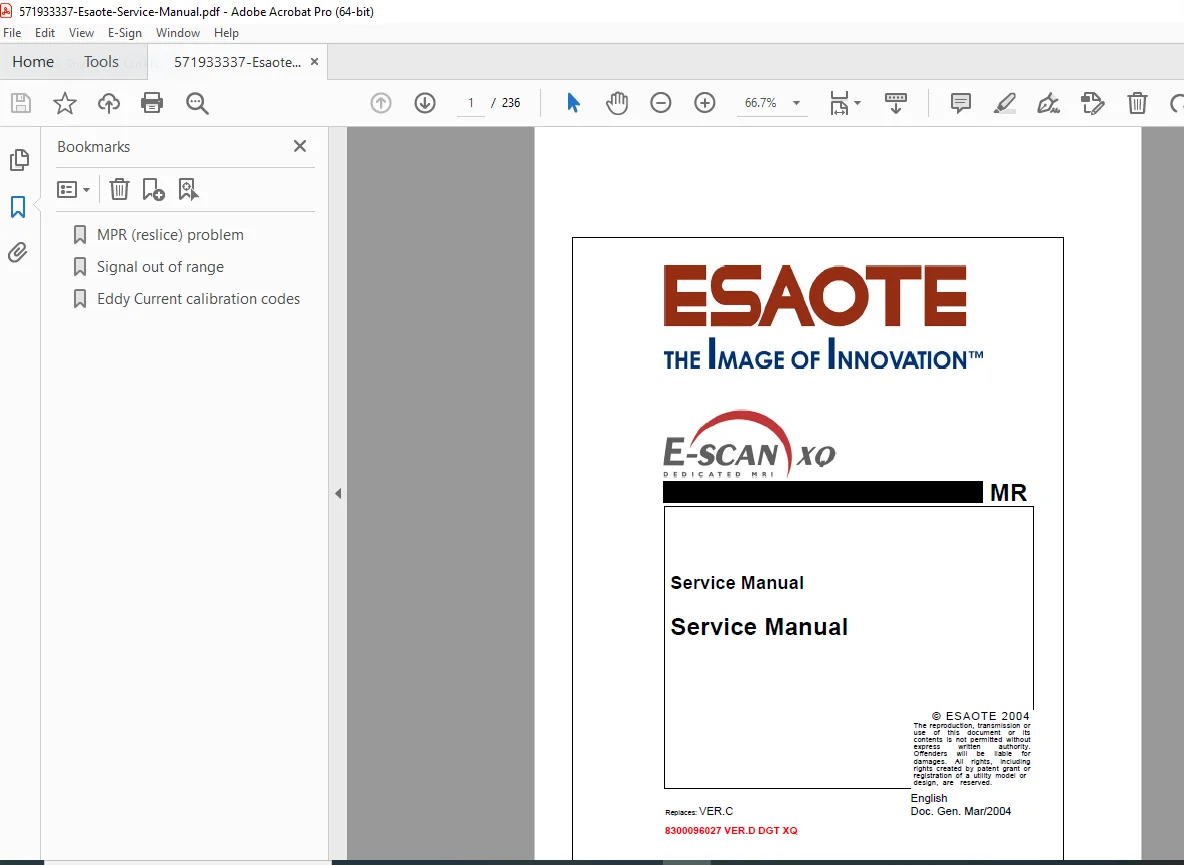
This is the official factory service manual for the Esaote E-SCAN XQ magnetic resonance imaging (MRI) scanner. Published in March 2004 (Version D) by Esaote S.p.A., this professional-grade technical documentation is essential for qualified biomedical technicians, MRI service engineers, and authorized service centers who maintain and repair this advanced permanent magnet MRI diagnostic imaging system.
📋 FILE DETAILS
- Manual Name: E-SCAN XQ Service Manual
- System Covered:
- Esaote E-SCAN XQ MRI Scanner
- 0.2 Tesla Permanent Magnet System
- Digital MRI System
- Manufacturer: Esaote S.p.A. (Italy)
- Publication Date: March 2004
- Version: D (Replaces Version C)
- Document Number: 8300096027 VER.D DGT XQ
- Total Pages: 236 pages
- File Format: PDF
- PDF Quality: High-quality official manual with detailed diagrams
- Language: English
- Page Size: A4 format
🔧 COMPREHENSIVE TABLE OF CONTENTS:
PART 1: INTRODUCTION
1. Overview
- Qualified personnel requirements
- Authorization and employment requirements
- New service support philosophy
- Modular system design
- Service friendliness concept
- Troubleshooting strategy overview
2. General
- Service manual introduction
- Manual contents overview
- FUN integration
- Concept structure explanation
- On-site trouble-shooting support
- Component isolation procedures
- Standard measurement procedures
2.1 Distribution
- Online documentation distribution
- Paper version distribution
- MR CSE distribution list
- System delivery changes
2.2 Service Manual Structure
- Table of Contents
- Introduction/Safety
- System
- Software
- Host
- Control
- RF system
- Patient handling
- Gradient system
- Magnet
- Power distribution
- Maintenance instructions
- Changes
- Index
2.3 Suggestions for Use
2.3.1 Strategy
- Flowchart guidelines
- Test procedure selection
- Problem-specific guidance
- General information resources
2.3.2 Procedures
- Detailed test instructions
- Standard procedures (SeSo startup, laptop connection)
- Log file reading
- Test result interpretation
2.3.3 Repair
- FRU replacement procedures
- Post-replacement adjustments
- Component installation instructions
2.3.4 Index
- Cross-reference system
- Topic redundancy for easy search
- Related topic information
PART 2: SERVICE POLICY
3. Product Line Support Center
3.1 Sales and Service Administration
3.2 Orders
- Ordering procedures
- Part number references
3.3 Repairs
3.3.1 General Conditions for Repair
3.3.2 Procedure for Returning Goods to ESAOTE
- Return authorization
- Shipping procedures
- Documentation requirements
3.3.3 Warranty After Repair
- Warranty terms
- Coverage details
PART 3: SYSTEM
4. Troubleshooting Strategy
4.1 System Functionality
- Functional overview
- System operation principles
4.2 System Error List
4.2.1 Window Messages Text Syntax
- Message format
- Syntax interpretation
4.2.2 Abbreviation Codes
- Standard abbreviations
- Code definitions
4.2.3 Symbols Used
- Symbol legend
- Warning indicators
4.2.4 Error Messages List
- Complete error code database
- NMR frequency calibration errors (20660, 20661, 20670, 26740, 26741)
- NMR Eddy Current analysis errors (14629-14636, 14650)
- Configuration errors
- Calculation failures
4.3 Troubleshooting
- Systematic troubleshooting approach
- Component isolation
5. Procedures
5.1 Recording Files Introduction
5.1.1 Rec File List
- Recording file types
- File structure
5.1.2 Service RecFilePlot Introduction
- Plot interpretation
- Data analysis
5.1.3 Monitored Quantities
- System monitoring
- Parameter tracking
5.2 System Check
5.2.1 Description 5.2.2 Operation 5.2.3 Functions
5.3 Image Quality
5.3.1 Common Interference Problem Analysis 5.3.2 Lines on Image 5.3.3 Shielding Efficiency 5.3.4 Detecting Artifacts on Images
6. Image Quality (Continued)
6.1 Multiple AC Sources
- Probe positioning
- Pick-Up Coil position
- Single source procedure (50/60 Hz)
- Single source procedure (16 Hz)
- Double sources procedure
7. Magnetic Compensation Test
7.1 Ghost Test 7.2 DC Ghost Test 7.3 Stability Test
8. Hardware Set-up
8.1 DC Probe or Single Probe 8.2 Probe Positioning 8.3 DC Compensation
9. AC Compensation
9.1 Multiple AC Sources
10. Repair
10.1 Magnetic Compensation Flag Settings 10.2 Repair Procedures 10.3 Component Replacement 10.4 Adjustments
PART 4: SOFTWARE
11. Trouble Shooting Strategy
11.1 Procedure
11.1.1 System Backup 11.1.2 Configurations Restore 11.1.3 Images Back Up 11.1.4 Images Restore
12. Repair
12.1 Complete Software Installation
12.1.1 Necessary Tools 12.1.2 Hardware Connection 12.1.3 Operating System SW Installation 12.1.4 OPI SW Installation 12.1.5 How to Solve Conflicts
PART 5: HOST
13. Trouble Shooting Strategy
13.1 Images Visualization and Storing
14. Procedure
14.1 Computer and Devices Test
14.1.1 CPU Board
- PCA6178V Pentium III
- Pentium III without SCSI on board (code 9730630037)
- Pentium III with SCSI on board (code 9730630043)
- SCSI On Board BIOS Setup
14.1.2 Hard Disk 14.1.3 External CD BURNER 14.1.4 Fujitsu M2513 Optical Disk Drive 14.1.5 SCSI PE LOGIC 1600 14.1.6 PRINT Board
15. Repair Instructions
15.1 Computer Board Set-up
PART 6: CONTROL
16. Trouble Shooting Strategy
17. Procedure
17.1 DSP Test
17.1.1 Necessary Tools 17.1.2 Operations
17.2 DSPCU Test
17.2.1 Necessary Tools 17.2.2 Operation
18. Repair Instructions
18.1 Change DSP or DSPCU Board
PART 7: RF SUBSYSTEM
19. Trouble Shooting Strategy
19.1 General
20. Procedure
20.1 Transmitting Coil Driving
20.1.1 Use of System Check
20.2 Receiving Chain Driving
20.2.1 How to Disable Automatic Coil Recognition
20.3 RFR Check
20.3.1 Procedure
20.4 SINT Check
20.4.1 Procedure
21. (RF Procedures Continued)
21.1 RFA Check
21.1.1 Procedure
22. Transmission Coil Check
23. Receiving Coils Check
23.1 Coil 1 – Shoulder 23.2 Coil 2 – Knee 23.3 Coil 3 – Hand 23.4 Coil 4 – Foot 23.5 Coil 5 – Shoulder
23.6 Coil 6 – Flex 23.7 Gantry Connectors
24. Repair
24.1 Transmission Coil
24.1.1 Necessary Tools 24.1.2 Operations 24.1.3 Tuning 24.1.4 Matching
24.2 Coil Lock
24.2.1 Sequence of Operation
24.3 Gantry
24.3.1 Sequence Operation
24.4 Receiving Coil
24.4.1 Introduction 24.4.2 Necessary Tools 24.4.3 Ordering Information 24.4.4 Tuning Procedure
PART 8: PATIENT HANDLING
25. Trouble Shooting Strategy
26. Procedure
26.1 Gradient Driving Transmitting Chain
26.1.1 Use of System Check
27. Repair
27.1 Magnet Brackets 27.2 Brackets Level 27.3 Round Part of Patient Table Level 27.4 Patient Table Mechanism 27.5 Patient Table Level
PART 9: GRADIENT
28. Trouble Shooting Strategy
29. Procedure
29.1 Necessary Tools 29.2 SGRA2 Replacement 29.3 Gradients Orientation
29.3.1 Introduction 29.3.2 Sequence Operation
30. (Gradient Procedures Continued)
30.1 4th Channel Polarity Check 30.2 SGRA2 Tune 30.3 Gradient Delay
31. Gain Gradient Calibration
31.1 Necessary Tools 31.2 Operations
32. Gradient Offset Calibration
33. Gradient Coils Replacement
33.1 Sequence Operation
34. Test and Adjustment Table
PART 10: MAGNET
35. Trouble Shooting Strategy
36. Procedure
36.1 Thermal Control
36.1.1 Temp. Monitor 36.1.2 Environment Temperature Control
36.2 Shimming Check
36.2.1 Phantom Positioning 36.2.2 Shimming Parameters Acquisition
37. Repair
37.1 Thermal Control
37.1.1 Check 37.1.2 Thermal Stability
37.2 Shimming
37.2.1 Access to Shimming Plates 37.2.2 Shimming Parameters Correction
37.3 Test and Adjustment Table
PART 11: POWER DISTRIBUTION
38. Introduction
39. Strategy
40. Repair
40.1 Checking the Line Voltage 40.2 Adapting Transformer to Line Voltage
PART 12: MAINTENANCE INSTRUCTIONS
41. Maintenance Protocol
42. Protective Conductor Test
43. Pavilion Maintenance
43.1 Fingers and Contact Surfaces
43.1.1 Upper and Lower Fingers 43.1.2 Fingers on Shutter Closing Set 43.1.3 Side Finger
43.2 Doors Sliding Device 43.3 Painting
🎯 E-SCAN XQ MRI SPECIFICATIONS:
MRI Technology: ✅ 0.2 Tesla permanent magnet system
✅ Digital MRI scanner
✅ Open architecture design
✅ Dedicated extremity imaging
✅ Multiple receiving coils (shoulder, knee, hand, foot, flex)
System Components: ✅ Console E-SCAN XQ
✅ E-SCAN magnet
✅ SPC Digital E-SCAN XQ
✅ Gantry kit E-SCAN
✅ Upper gradient kit
✅ Lower gradient kit
Imaging Capabilities: ✅ Permanent magnet technology
✅ No cryogens required
✅ Low operating costs
✅ Orthopedic and extremity focus
✅ Patient-friendly open design
Computer System: ✅ Pentium III processor options
✅ SCSI on-board variants
✅ Hard disk storage
✅ CD burner
✅ Optical disk drive
✅ Print board
RF System: ✅ Transmitting coil with tuning/matching
✅ Six receiving coils (specialized anatomical)
✅ Automatic coil recognition
✅ RFR, SINT, RFA checks
✅ Gantry connectors
Gradient System: ✅ SGRA2 gradient amplifier
✅ 4th channel capability
✅ Gradient delay calibration
✅ Gain calibration
✅ Offset calibration
✅ Upper and lower gradient coils
Magnet System: ✅ Permanent magnet (0.2T)
✅ Thermal stability control
✅ Temperature monitoring
✅ Shimming system with adjustment plates
✅ NMR-based calibration
💡 IDEAL FOR:
✅ Hospital biomedical engineering departments
✅ MRI service engineers
✅ Authorized Esaote service centers
✅ Medical imaging equipment specialists
✅ Clinical engineering technicians
✅ Healthcare technology management professionals
✅ Diagnostic imaging service providers
✅ Radiology department technical staff
✅ Anyone servicing Esaote MRI systems
🌟 KEY BENEFITS:
- Comprehensive 236 Pages: Complete MRI system documentation
- 0.2T Permanent Magnet MRI: Specialized extremity imaging system
- Complete Error Code Database: NMR calibration and Eddy current errors
- RF Subsystem Documentation: Six coil configurations with tuning procedures
- Gradient Calibration: Gain, offset, and delay calibration procedures
- Shimming Procedures: Magnetic field homogeneity optimization
- Software Installation: Complete OS and OPI software procedures
- Patient Table Service: Mechanical alignment and level procedures
- Image Quality Analysis: Artifact detection and interference troubleshooting
- Official Esaote Documentation: Factory service procedures
📥 DOWNLOAD INFORMATION:
- Instant Download: Immediate access after purchase
- Format: PDF with searchable text
- Compatibility: Works on PC, Mac, tablet, smartphone
- Searchable: Full-text search capability
- Printable: Print entire manual or sections
- High Quality: Clear diagrams and schematics
- Professional: Official Esaote S.p.A. documentation
⚠️ IMPORTANT NOTES:
- Professional service manual for qualified biomedical technicians
- Permanent magnet MRI system (0.2 Tesla)
- Official Esaote S.p.A. documentation
- NMR calibration procedures included
- Electrical safety compliance mandatory
- Magnetic field safety precautions
- Proper training and authorization required
- RF safety protocols must be followed
🔧 REQUIRED SERVICE EQUIPMENT:
- System Check software
- Laptop for Host connection
- Digital Multimeter
- Oscilloscope
- RF power meter
- Gradient test equipment
- NMR frequency analyzer
- Phantom (for shimming)
- Temperature monitoring equipment
- Specialized Esaote service tools
- SCSI diagnostic tools
- Software installation media
🌟 WHY CHOOSE THIS MANUAL?
This is authentic Esaote S.p.A. factory documentation for the E-SCAN XQ permanent magnet MRI scanner. The E-SCAN XQ represents specialized extremity MRI technology requiring factory-level service procedures to maintain image quality, magnetic field homogeneity, and patient safety. The manual’s comprehensive 236-page coverage makes it essential for hospital biomedical departments and authorized service centers.
Order now for immediate download access to complete Esaote E-SCAN XQ MRI scanner service documentation!