Esaote E-Scan XQ MRI Service Manual 8300096028 Ver C Complete Guide PDF
Original price was: $85.00.$28.95Current price is: $28.95.
Complete service manual for Esaote E-Scan XQ low-field MRI system. Comprehensive 212-page technical reference covering troubleshooting strategies, system functionality, error messages, software installation, hardware diagnostics, RF subsystem testing, magnetic compensation, coil tuning, and repair procedures. Essential for biomedical engineers and MRI service technicians performing maintenance, diagnostics, and repairs on Esaote extremity MRI scanners used in orthopedic imaging applications.
Description
Esaote E-Scan XQ MRI Service Manual 8300096028 Ver C Complete Guide – PDF DOWNLOAD
DESCRIPTION
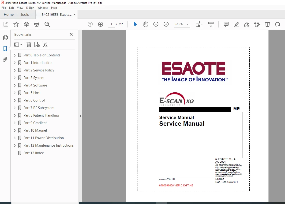
This comprehensive 212-page service manual provides complete technical documentation for the Esaote E-Scan XQ MRI System, a dedicated extremity magnetic resonance imaging scanner. Published by Esaote S.p.A. (Document Number 8300096028 Version C, October 2004), this is the authoritative OEM reference for qualified biomedical equipment technicians, clinical engineers, and MRI service specialists working with this specialized imaging system.
Manual Overview & System Description
Esaote E-Scan XQ System:
- Low-field dedicated extremity MRI scanner
- Optimized for orthopedic imaging applications
- Specialized coils for shoulder, knee, hand, foot, and ankle imaging
- Compact footprint for point-of-care installations
- Permanent magnet technology (low field strength)
- Office-based MRI solution for orthopedic practices
- No cryogen requirements (permanent magnet design)
Document Information:
- Publication Number: 8300096028 VER.C DGT NE
- Document Date: October 2004
- Language: English
- Replaces: Version B
- Author: Esaote S.p.A., Genoa, Italy
- Created With: FrameMaker 6.0
- Page Size: A4 (595 x 842 pts)
Comprehensive Manual Structure
PART 1: INTRODUCTION
Overview:
- Manual purpose and scope
- Target audience (qualified service personnel only)
- Document structure explanation
- Safety and regulatory information
General Guidelines:
- Suggestions for effective manual use
- Troubleshooting strategy overview
- Test procedure organization
- Repair procedure framework
- Documentation conventions
PART 2: SERVICE POLICY
Product Line Support Center:
- Contact Information:
- Esaote S.p.A, Via Siffredi 58, 16153 Genoa, Italy
- Service hours: 8:00 AM – 5:00 PM (local time), Monday-Friday
- Fax: +39 10 6547275
- Email: [email protected]
- Language: English communications required
Sales and Service Administration:
- Service manual distribution and updates
- Service information bulletins
- Service training programs
- Product part lists and ordering
- Part repair processes
- Online support (email, phone, fax)
Orders:
- Spare parts ordering procedures
- Part number identification
- Order processing and tracking
- Documentation for replacement components
Repairs:
- General Conditions for Repair:
- Authorized service personnel requirements
- Qualification standards
- ESAOTE affiliate authorization
- Installation and service restrictions
- Procedure for Returning Goods to ESAOTE:
- RMA (Return Merchandise Authorization) process
- Packaging requirements
- Shipping instructions
- Documentation requirements
- Warranty After Repair:
- Warranty terms and conditions
- Coverage limitations
- Claim procedures
- Service documentation requirements
PART 3: SYSTEM OVERVIEW
System Functionality:
- Overall system architecture
- Major subsystem descriptions
- Signal flow diagrams
- Control hierarchy
- Data processing pathways
- Image acquisition and reconstruction
System Components:
- Magnet assembly (permanent magnet)
- RF transmission coil
- Multiple receiving coils (specialized for anatomy)
- Gradient system
- Computer host system
- Control electronics
- Power distribution
- Cooling system
PART 4: SYSTEM TROUBLESHOOTING
Troubleshooting Strategy:
- Systematic diagnostic approach
- Symptom-based flowcharts
- Error isolation methodology
- Test equipment requirements
- Safety precautions during testing
System Error Message List:
- Comprehensive Error Code Reference:
- Error type classification
- Error source identification
- Error descriptions and meanings
- Recommended corrective actions
Error Categories:
- Type: System, hardware, software, RF, gradient
- Source: Subsystem identification
- Error: Specific fault codes and descriptions
- Resolution: Troubleshooting steps
Troubleshooting Procedures:
- Step-by-step diagnostic procedures
- Component isolation techniques
- Test point locations
- Expected measurement values
- Interpreting test results
PART 5: RECORDING FILES AND DIAGNOSTICS
Recording Files Introduction:
- System logging capabilities
- Data capture during operation
- Error logging and analysis
- Performance monitoring
Rec File List:
- Available recording file types
- File naming conventions
- File location in system directories
- File interpretation guidelines
Service RecFilePlot Introduction:
- Graphical data analysis tool
- Monitored Quantities:
- Signal levels
- Temperature readings
- Power supply voltages
- RF power measurements
- Gradient performance parameters
- System timing parameters
System Check Procedures:
- Description: Automated system verification tests
- Operation: How to run system diagnostics
- Functions: Built-in test capabilities
Test Categories:
- Hardware verification tests
- Software integrity checks
- RF subsystem performance
- Gradient linearity testing
- Image quality assessment
PART 6: IMAGE QUALITY ANALYSIS
Image Quality Assessment:
- Common Interference Problem Analysis:
- RF interference identification
- Gradient artifacts
- Motion artifacts
- Chemical shift artifacts
- Aliasing and wrap-around
Shielding Efficiency:
- RF shielding verification
- Faraday cage integrity testing
- Ground loop detection
- External interference sources
Detecting Artifacts on Images:
- Artifact identification guide
- Cause analysis
- Correction procedures
- Image quality metrics
Specific Tests:
- Signal-to-noise ratio (SNR) measurements
- Uniformity testing
- Spatial resolution verification
- Contrast measurements
- Geometric distortion assessment
PART 7: MAGNETIC COMPENSATION
MTCM Check:
- Main Transmission Coil Module verification
- Functionality testing
- Performance measurements
Magnetic Compensation Procedures:
- Magnetic Compensation Flag Settings:
- Configuration parameters
- Optimization settings
- System-specific adjustments
Magnetic Compensation Test:
- Ghost Test:
- Phase ghost detection
- Frequency ghost analysis
- Ghost artifact quantification
- DC Ghost Test:
- DC offset identification
- Baseline stability verification
- Correction procedures
- Stability Test:
- Long-term signal stability
- Frequency drift monitoring
- Amplitude stability verification
- Temperature-related variations
PART 8: SOFTWARE
Troubleshooting Strategy:
- Software-related problem diagnosis
- Operating system issues
- Application software problems
- Database corruption
- Network connectivity
System Backup Procedures:
- Complete system backup methodology
- Backup frequency recommendations
- Storage media requirements
- Backup verification procedures
Images Backup:
- Patient data backup procedures
- DICOM database backup
- Image archive management
- Data retention policies
Configurations Restore:
- System configuration file restoration
- User settings recovery
- Protocol restoration
- Database rebuild procedures
Images Restore:
- Patient image recovery procedures
- Archive restoration
- Database consistency checks
Complete Software Installation:
- Operating System Installation:
- Windows installation procedures
- Driver installation
- System configuration
- Operating System Service Pack 4 Installation:
- Service pack update procedures
- Compatibility verification
- Post-installation testing
- OPI SW Installation:
- Operator interface software installation
- Configuration procedures
- License activation
- Software verification testing
PART 9: HOST COMPUTER SYSTEM
Troubleshooting Strategy:
- Computer hardware diagnostics
- Performance issues
- Peripheral problems
Images Visualization and Storing:
- Display system verification
- Hard disk performance
- Data storage integrity
Computer and Device Tests:
- CPU Board:
- Processor functionality testing
- Memory testing
- System board diagnostics
- Pentium IV: Award BIOS Setup Utility:
- BIOS configuration settings
- Boot sequence configuration
- Hardware detection
- Performance settings
- Power management
Hard Disk:
- Disk drive testing
- Bad sector detection
- Performance benchmarks
- Disk replacement procedures
CD Combo Drive:
- CD-ROM/CD-RW testing
- Media compatibility
- Drive calibration
Optical Disk Drive:
- DVD drive testing
- Read/write verification
- Media handling
Computer Board Setup:
- Motherboard configuration
- Jumper settings
- BIOS parameters
- Device installation
PART 10: CONTROL SYSTEM
Troubleshooting Strategy:
- Control electronics diagnosis
- Signal processing verification
- Communication testing
DSPM and Signal Box Tests:
- Operation: Digital signal processor testing
- Data Cable Check: Communication integrity verification
ACM Test:
- Acquisition Control Module testing
- Operation: Functional verification procedures
- Performance measurements
- Timing verification
ACM and SRFA Check:
- Synchronization testing
- Procedure: Step-by-step test instructions
- SRFA LED Status Check: Visual indicator interpretation
Change Procedures:
- Change DSPM Card: Replacement procedures
- Change ACM Module: Module replacement and configuration
PART 11: RF SUBSYSTEM
Troubleshooting Strategy:
- RF system overview
- Common RF problems
- Systematic diagnostic approach
Transmitting Coil Driving:
- RF amplifier testing
- Use of System Check: Automated testing procedures
- Power output verification
- Frequency accuracy
Receiving Chain Driving:
- Automatic Coil Recognition: Coil ID system verification
- Preamplifier testing
- Signal path integrity
RFM Check:
- RF Module functionality testing
- Procedure: Detailed test instructions
- Performance specifications
Transmission Coil Check:
- Operations: Coil testing procedures
- RF homogeneity testing
- Power delivery verification
- Safety interlocks
Receiving Coils Check:
- Coil-Specific Testing:
- Coil 1: Shoulder – Tuning and matching verification
- Coil 2: Knee – Performance testing
- Coil 3: Hand – Signal quality assessment
- Coil 4: Foot – Coil integrity verification
- Coil 5: Shoulder (alternate configuration)
Gantry Connectors:
- Connector pin identification
- Continuity testing
- Cable integrity verification
- Connector replacement procedures
PART 12: RF SUBSYSTEM REPAIR
Transmission Coil Repair:
- Necessary Tools:
- RF power meter
- Network analyzer
- Tuning tools
- Test fixtures
- Adjustment Procedure:
- Coil tuning methodology
- Matching network adjustment
- Performance optimization
- Verification testing
Coil Lock Mechanism:
- Sequence of Operation:
- Mechanical lock/unlock procedures
- Interlock testing
- Safety verification
- Adjustment procedures
Gantry Service:
- Sequence Operation:
- Gantry movement testing
- Position sensors
- Mechanical adjustments
- Cable routing
Receiving Coil Service:
- Introduction: Coil construction and operation
- Necessary Tools: Specialized equipment requirements
- Tuning Procedure:
- Frequency adjustment
- Matching optimization
- Q-factor measurement
- Performance verification
File Specifications
| Specification | Details |
|---|---|
| Manual Title | Esaote E-Scan XQ Service Manual |
| Document Number | 8300096028 VER.C DGT NE |
| Total Pages | 212 pages |
| File Format | |
| File Size | 20.6 MB |
| PDF Version | 1.4 |
| Creator | FrameMaker 6.0 |
| Producer | Acrobat Distiller 5.0 |
| Document Date | October 2004 |
| Page Size | A4 (210 x 297 mm) |
| Copyright | © Esaote S.p.A. |
| Language | English |
Key Manual Features
✓ 212 comprehensive pages of OEM technical documentation
✓ Complete system architecture and signal flow diagrams
✓ Error message reference with codes and solutions
✓ Magnetic compensation procedures for image optimization
✓ RF subsystem testing including all specialized coils
✓ Software installation guides (OS and application)
✓ Image quality assessment procedures and artifact analysis
✓ Hardware diagnostics for computer and control systems
✓ Coil tuning procedures for all anatomical coils
✓ System backup and restore procedures
✓ Troubleshooting flowcharts for systematic diagnosis
✓ Repair procedures with adjustment specifications
Target Users
This service manual is essential for:
- Biomedical Equipment Technicians (BMETs) specializing in MRI systems
- Clinical Engineers managing imaging equipment
- MRI Service Engineers performing diagnostics and repairs
- Field Service Representatives for Esaote systems
- Hospital Biomedical Engineering Departments
- Independent Medical Equipment Service Companies
- Authorized Esaote Service Centers
- Technical Training Instructors teaching MRI service
- Imaging Center Technical Staff
Clinical Applications
The Esaote E-Scan XQ extremity MRI system serves specialized imaging needs:
Orthopedic Applications:
- Knee Imaging – meniscal tears, ligament injuries (ACL, MCL, PCL, LCL), cartilage defects
- Shoulder Imaging – rotator cuff tears, labral tears, impingement syndrome
- Hand & Wrist – carpal tunnel, ligament injuries, fracture assessment
- Foot & Ankle – tendon tears, ligament injuries, stress fractures
- Elbow Imaging – tendon evaluation, ligament assessment
Clinical Settings:
- Orthopedic specialty practices
- Sports medicine clinics
- Outpatient imaging centers
- Hospital emergency departments
- Urgent care facilities
- Physical therapy centers
- Occupational health clinics
Advantages of Dedicated Extremity MRI:
- Lower cost compared to whole-body MRI
- Smaller footprint for office-based installations
- Patient-friendly open design (less claustrophobia)
- No cryogen requirements (permanent magnet)
- Lower power consumption
- Point-of-care imaging capability
- Faster patient throughput
Why This Manual is Essential
The Esaote E-Scan XQ is a sophisticated low-field MRI system requiring specialized knowledge, proper service procedures, and diagnostic techniques for reliable operation. This comprehensive service manual provides the complete factory-authorized information necessary to:
- Perform accurate diagnostics using systematic troubleshooting strategies
- Interpret error messages with complete error code reference
- Maintain image quality through magnetic compensation procedures
- Service RF subsystems including all specialized anatomical coils
- Execute software installations for operating system and applications
- Optimize system performance through proper adjustments and calibrations
- Ensure patient safety through proper testing and verification
- Reduce system downtime with effective troubleshooting procedures
- Order correct parts using proper part identification
- Meet manufacturer standards for quality service
- Extend system life through proper preventive maintenance
- Maintain regulatory compliance through authorized procedures
Whether performing routine preventive maintenance, diagnosing image quality problems, replacing RF components, troubleshooting computer systems, tuning receiving coils, or executing complete software reinstallations, this 212-page service manual provides the authoritative technical reference required for professional-quality work on Esaote E-Scan XQ extremity MRI systems.