
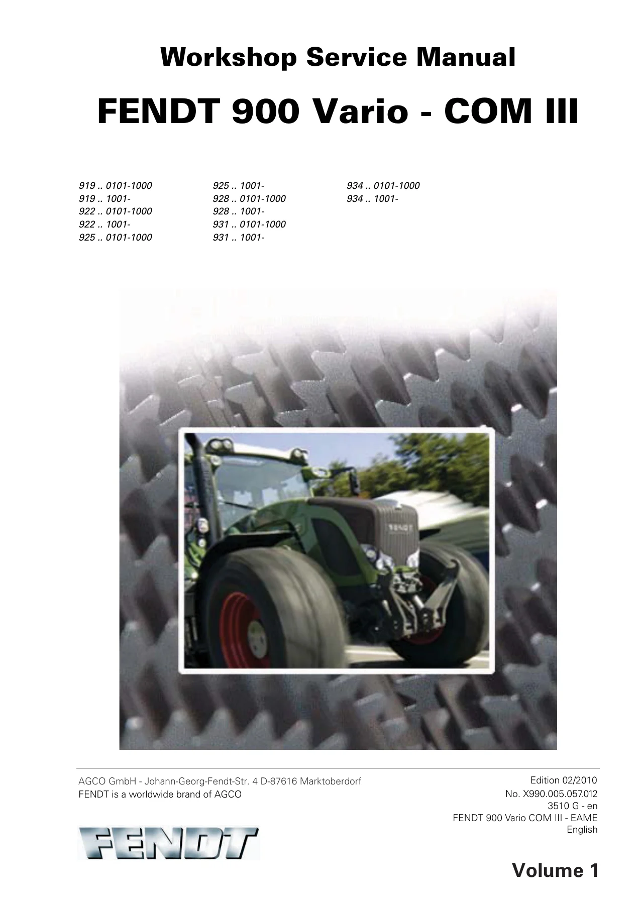
Fendt 900 Vario COM III Workshop Service Manual Volume 1 – 922 924 927 930 933 936 Vario Tractor – PDF Download
Original price was: $48.95.$34.95Current price is: $34.95.
Complete Fendt 900 Vario COM III Workshop Service Manual Volume 1 covering 922, 924, 927, 930, 933, and 936 Vario tractors. Engine, transmission, hydraulics, electrical systems, diagnostics, and more. Instant PDF download.
Description
Fendt 900 Vario COM III Workshop Service Manual – Volume 1
This is the complete Fendt 900 Vario COM III Workshop Service Manual, Volume 1, published by AGCO GmbH for the FENDT 900 Vario COM III series tractors. This volume covers the 922 Vario, 924 Vario, 927 Vario, 930 Vario, 933 Vario, and 936 Vario models, and is an essential resource for technicians, workshop professionals, and serious owners who need factory-level repair and diagnostic information. The manual is written in English and covers the Deutz TCD 2013 L6 4V engine and the ML 260 continuously variable transmission.
File Details
- Manual Type: Workshop Service Manual
- Brand: FENDT (AGCO)
- Models Covered: 922 Vario, 924 Vario, 927 Vario, 930 Vario, 933 Vario, 936 Vario
- Engine: Deutz TCD 2013 L6 4V
- Language: English
- Edition: 02/2010
- Document Number: X990.005.057.012 3510 G – en
- Volume: 1
- Format: PDF
Chapters Covered
- 0000 – Overall system/tractor
- 1005 – Overall system/transmission
- 1010 – Transmission/differential
- 1015 – Transmission/axle drive
- 1050 – Transmission/housing
- 1070 – Transmission/Brake system
- 1080 – Transmission/drive train
- 1200 – Transmission/front PTO
- 1220 – Transmission/Live PTO
- 1320 – Transmission/front wheel drive
- 2000 – Overall system/engine
- 2010 – Engine/cylinder head
- 2050 – Engine/cooling
- 2060 – Engine/fuel system
- 2210 – Engine/crankcase
- 2312 – Engine/lubrication
- 2400 – Engine/exhaust system
- 2712 – Engine/injectors
- 3000 – Overall system/front axle
- 3120 – Front axle/steering cylinder
- 3180 – Front axle/cardan shaft
Overall System & Diagnostics
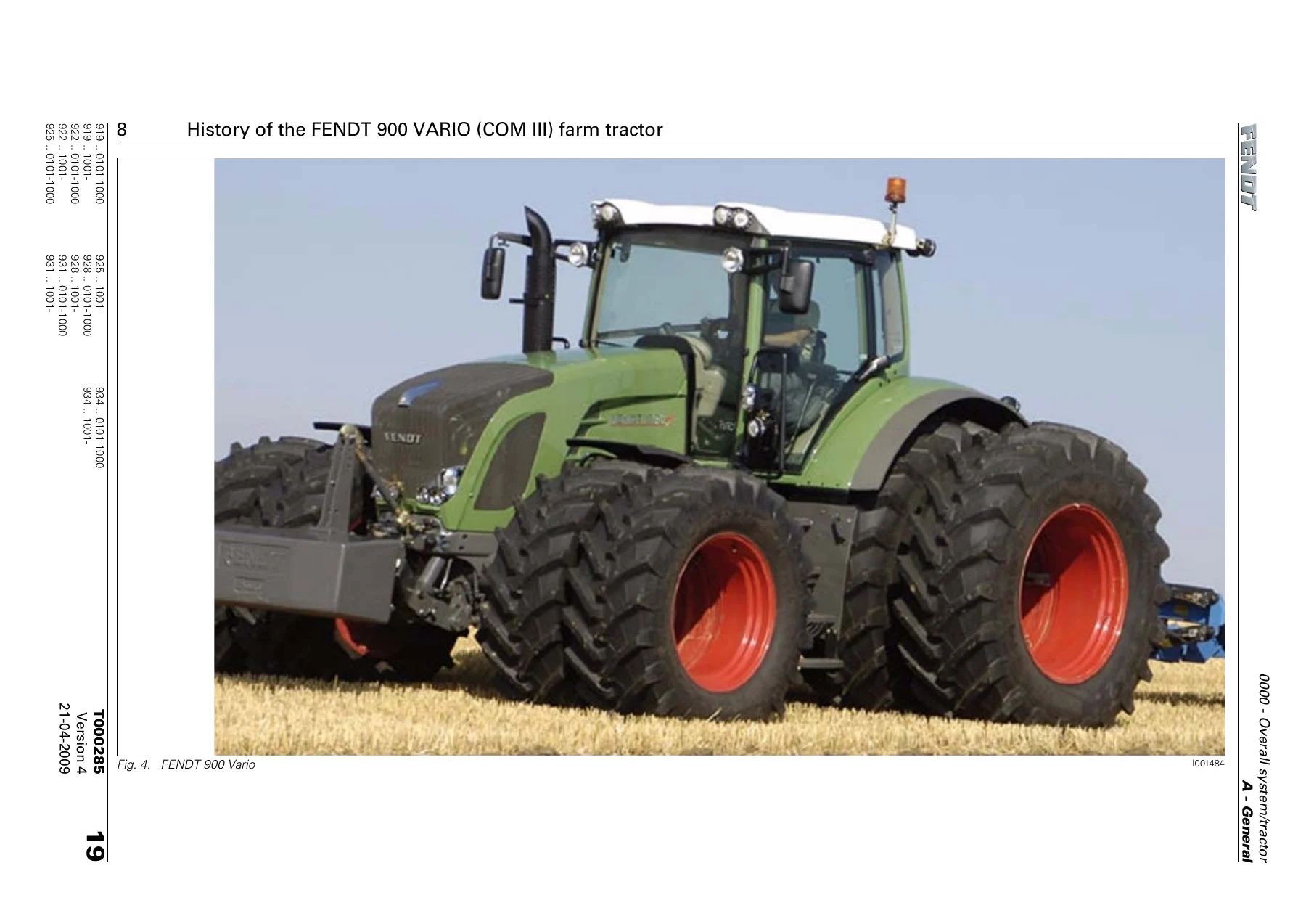
Chapter 0000 provides the complete framework for working on the 900 Vario COM III. It includes the full fault code tables (00.0.00 through 1E.1.00), component position guides with photographic references, safety briefing and measures, tightening torques for metric bolts in Nm (kpm), biodiesel and biodegradable hydraulic oil guidance, and the tractor diagnostics procedure using the terminal. This is where you’ll find the calibration fault codes and the step-by-step instructions for reading, confirming, and deleting fault codes. Also included is the history of the FENDT 900 Vario (COM III) farm tractor with full technical specification extracts for the engine, transmission, front axle, front PTO, hydraulics, cab, and electrics/electronics. The component position chapter is particularly valuable, with photographic references for every major electrical and hydraulic component, including the A007 instrument panel, A009 actuator unit, A050 ECU basic control unit, A051 ECU engine control unit (EDC 7), A053 air conditioning control, A055 data transfer ECU, and the full range of sensors including B055 foot throttle, B085 camshaft speed, B086 rail pressure, B087 fuel low pressure, B088 crankshaft speed, B089 engine temperature, B090 oil pressure, B091 water in fuel, and B092 charge air pressure/temperature.
Transmission & Drivetrain
The transmission chapters form the largest part of Volume 1. Chapter 1005 explains the ML 260 continuously variable transmission (CVT) function, including the hydrostatic and mechanical power distribution, the transmission hydraulic system diagram, and the complete functional sequence. You’ll find the transmission control system, pressure measuring points, and the procedures for measuring transmission pressure and enhanced control pressure. The high-pressure circuit, purge valve, clutch pressure-limiting valve, and turbo-clutch pressure-limiting valve are all documented.
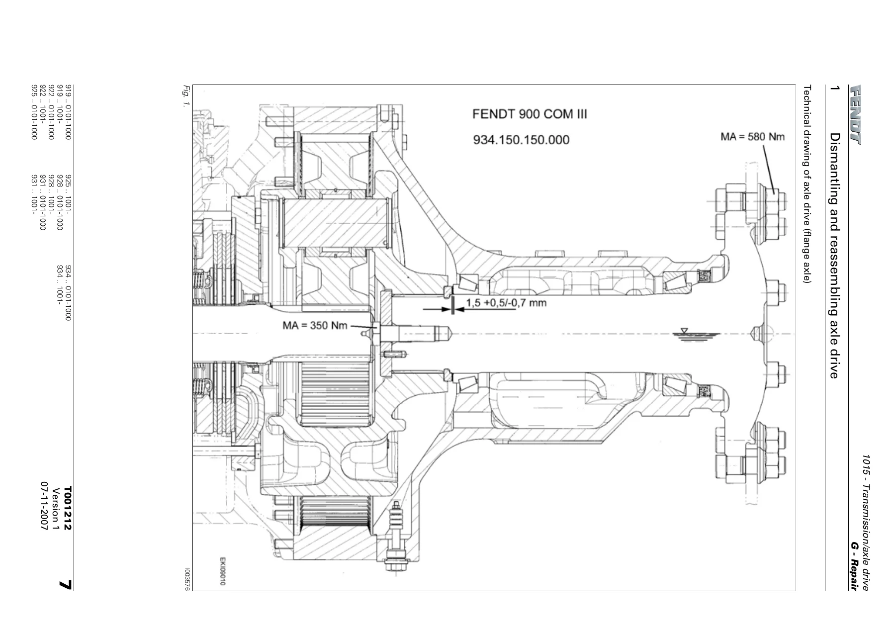
Chapters 1010, 1015, 1050, 1070, 1080, 1200, 1220, and 1320 cover the disassembly, assembly, adjustment, and repair of the differential gear, axle drive, transmission housing, brake system, drive train, front PTO, live PTO, and front wheel drive. Each procedure is documented with step-by-step instructions, torque values, and photographic references. Critical adjustments like pinion shaft ring gear backlash, differential roll resistance, and rear wheel brake adjustment are covered in detail. The differential gear removal and installation procedures include the use of special tools, the correct sequence for disc pack assembly, and the adjustment of bearing preload. The axle drive chapter covers both flange and stub shaft versions, with detailed instructions for dismantling and reassembling the planetary carrier, rear axle shaft, and taper roller bearings. The brake system chapter includes the technical drawings for the rear wheel brake, actuator cylinder, and wheel brake cylinder, plus the adjustment procedures for the rear wheel brake and the S086/S087 brake wear switches.
Engine Systems
Chapter 2000 opens with a general description of the Deutz Common Rail (DCR) system, emergency mode operation, the A051 ECU (EDC 7), and the full range of engine sensors including the B055 foot throttle, B085 camshaft speed sensor, B086 rail pressure sensor, B087 fuel low pressure sensor, B088 crankshaft speed sensor, B089 engine temperature sensor, B090 oil pressure sensor, B091 water in fuel sensor, and B092 charge air pressure/temperature sensor. Engine fault tables are included, covering the complete range of fault codes from 1E.1.00 through 1E.1.F0, with causes, consequences, and the SERDIA diagnostic references.
Chapter 2010 covers valve adjustment for the Deutz TCD 2013 engine with the specified valve clearance values (75° inlet / 105° exhaust) and the X899.980.236.030 adjustment tool. The valve adjustment diagram and the correct sequence for rotating the engine are provided. Chapter 2050 provides the complete coolant circuit diagram, the B077 electrical viscous fan operation and testing, and removal/fitting procedures for the radiators and cooler assembly. The coolant circuit diagram identifies the water pump, thermostat, expansion tank, engine oil cooler, and the water-cooled injectors.
Chapter 2060 covers the fuel system in depth: water sedimentor, fuel pump, Y091 dispensing unit, high-pressure pump (PF 45), high-pressure accumulator (rail), high-pressure limiting valve, and injector valves Y095 to Y101. Fuel pressure measurement procedures and fuel system bleeding are documented, including the measurement of fuel return pressure, fuel low pressure, and fuel pressure at the Y091 dispensing unit. The injector valve design and function are explained with cutaway diagrams showing the idle state, start of injection, and end of injection phases.
Chapter 2210 covers crankcase air bleed. Chapter 2312 provides the full engine lubrication diagram with oil filter console details, the lubrication pump, and the piston cooling nozzles. Chapter 2400 explains the Y094 actuator unit for exhaust gas recirculation, including the functional description and the calibration procedure after replacement. Chapter 2712 covers injector valve testing and cylinder switch-off procedures using the X899.980.259.101 adapter cable.
Front Axle
Chapter 3000 provides the front axle overview with Dana and Carraro axle identification (including the 970/130, 970/140, and 730/124 series), the front axle suspension functional description and operation, and the complete repair procedures for removing and fitting the front axle. The functional plans for the suspension system cover the raise, lower, locking, and wobble stabiliser operating states. Chapter 3120 provides technical drawings for the steering cylinder and track rod, including the seal set and the correct fitting procedure. Chapter 3180 provides the technical drawing for the front-wheel drive shaft and clutch housing, with the complete parts breakdown and the procedure for assembling and dismantling the live PTO clutch and gears.
Why This Manual Matters
The FENDT 900 Vario COM III is a complex, high-value agricultural machine. Working on the ML 260 transmission, the Deutz Common Rail engine, the front axle suspension, or the electro-hydraulic systems without the correct procedures and specifications is risky and expensive. This workshop manual gives you the actual torque values, pressure readings, calibration codes, and step-by-step repair instructions that FENDT technicians use. Whether you’re diagnosing a fault code, calibrating a sensor, overhauling the transmission, or adjusting the rear wheel brake, the correct information is here. The fault code tables alone are invaluable, covering everything from CAN bus communication faults to injector valve errors, with the exact fault code numbers, causes, consequences, and the corresponding SERDIA diagnostic references. The calibration procedures cover all the critical sensors and actuators, including the rear EPC, front EPC, crossgate lever, linear modules, front axle suspension, steering angle sensor, Auto-Guide control valve, PTO clutches, drive clutch pedal, hand throttle, travel range selector, foot throttle, transmission ratio characteristic, and turbo-clutch function.
IMAGES PREVIEW
Instant PDF Delivery
This manual is delivered as an instant PDF download after payment. There’s no shipping, no waiting, and no physical book to handle. You can view it on any device — laptop, tablet, or smartphone — and print the pages you need for the workshop. Keep it on your computer, load it onto a workshop tablet, or print the sections you use most. The FENDT 900 Vario COM III Workshop Service Manual Volume 1 is a working document, and the PDF format means you can search, print, and work with it however suits your workflow. Whether you’re a professional technician, a workshop manager, or a farmer who maintains their own equipment, this manual provides the detailed technical information you need to keep your FENDT 900 Vario COM III running correctly and safely.
Get the complete FENDT 900 Vario COM III workshop manual Volume 1 today — instant PDF download, full coverage of 922, 924, 927, 930, 933, and 936 Vario tractors.
Reviews
There are no reviews yet.