Trusted Business
Verified & Licensed
Virus Free Files
100% Safe Downloads
Secure Payment
SSL Protected
Instant Delivery
Available Immediately
Fiat Hitachi Wheel Loader W270 Service Manual – PDF DOWNLOAD
$27.95
Fiat Hitachi Wheel Loader W270 Service Manual – PDF DOWNLOAD
Instant PDF Download
Available immediately
Save to Your Device
Download & keep forever
Antivirus Scanned
100% virus-free
Trusted Worldwide
175,000+ customers
Description
Fiat Hitachi Wheel Loader W270 Service Manual – PDF DOWNLOAD
FILE DETAILS:
Fiat Hitachi Wheel Loader W270 Service Manual – PDF DOWNLOAD
Language : English
Pages : 375
Downloadable : Yes
File Type : PDF
DESCRIPTION:
Fiat Hitachi Wheel Loader W270 Service Manual – PDF DOWNLOAD
SAFETY RULES
GENERALITIES
- Read this Manual carefully before starting, operating, maintaining, fuelling or servicing the machine. Read and comply with all safety precautions before any intervention. Do not allow unauthorised personnel to operate or service this machine. Do not wear rings, wrist watches, jewellery, loose or hanging garments, such as ties, torn clothing, scarves, unbuttoned or unzipped jackets that can get caught in moving parts.
- Wear certified safety clothes such as: hard hat, noslip footwear, heavy gloves, ear protection, safety glasses, reflector vests, respirators. Ask your employer about specific safety equipment requirements. Keep the operator’s compartment, step plates, grab-rails and handles clean and clear of foreign objects, oil, grease, mud or snow to minimize the danger of slipping or stumbling. Remove mud or grease from your shoes before attempting to mount or operate the machine. Do not jump on or off the machine.
- Always keep both hands and one foot, or both feet and one hand in contact with steps and grab rails. Do not use controls or hoses as hand holds when climbing on or off the machine. Hoses and controls are movable parts and do not provide solid support. Besides, controls may be inadvertently moved and cause unexpected movement of the machine or its attachments. Never operate the machine or its attachments from any position other than sitting in the driver’s seat. Keep head, body, limbs, hands and feet inside the operator’s compartment at all times to reduce exposure to external hazards .
- Be careful of possible slippery conditions of the steps and hand rails as well as of the ground around the machine. Do not leave the machine until it is has come to a complete stop. Check the seat safety belt at least twice per year and replace it if it shows signs of wear, fraying or other weakness that could lead to failure.
IMAGES PREVIEW OF THE MANUAL:
TABLE OF CONTENTS:
Fiat Hitachi Wheel Loader W270 Service Manual – PDF DOWNLOAD
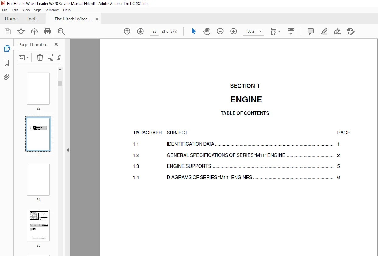
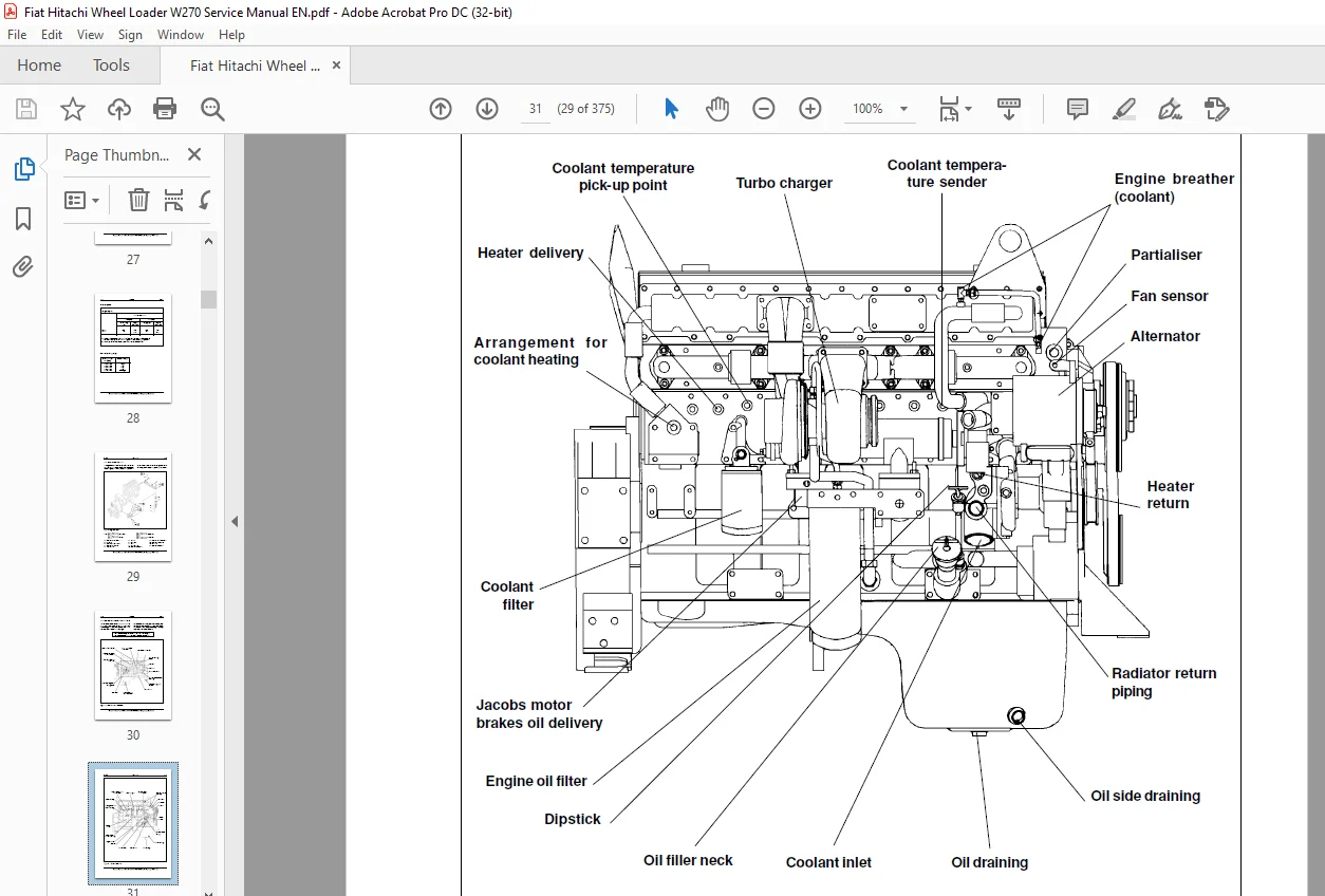
Service Manual W270...............................................................................  1
S U M M A R Y.....................................................................................  5
SAFETY RULES......................................................................................  7
SPECIFICATIONS - WHEEL LOADER W270................................................................ 14
FLUIDS AND CAPACITY TABLE......................................................................... 16
UNITS OF MEASURE.................................................................................. 17
TORQUE TABLES..................................................................................... 18
SECTION 1 ENGINE.................................................................................. 21
	1.1 IDENTIFICATION DATA....................................................................... 23
	1.2 GENERAL SPECIFICATIONS OF “M11” SERIES ENGINE............................................. 24
	1.3 ENGINE SUPPORTS........................................................................... 27
	1.4 SERIES "M11" ENGINE DIAGRAMS.............................................................. 28
SECTION 2 TRANSMISSION............................................................................ 31
	2.1 GENERAL DESCRIPTION....................................................................... 33
	2.2 TORQUE CONVERTER - TRANSMISSION........................................................... 34
	2.3 TORQUE CONVERTER.......................................................................... 40
	2.4 TORQUE CONVERTER PUMP..................................................................... 42
	2.5 TRANSMISSION.............................................................................. 43
		2.5 .1 POWER TRAIN DIAGRAM................................................................ 47
		2.5.2 TRANSMISSION CONTROLVALVE........................................................... 49
	2.6 AUTOMATIC TRANSMISSION CONTROL SYSTEM..................................................... 64
	2.7 TRANSMISSION SELECTOR..................................................................... 71
	2.8 OIL CIRCUIT............................................................................... 76
	2.9 DISASSEMBLY TRANSMISSION.................................................................. 78
	2.10 REASSEMBLY TRANSMISSION..................................................................105
	2.11 TROUBLESHOOTING GUIDE....................................................................132
	2.12 STANDARD VALUES FOR MAINTENANCE..........................................................135
	2.13 Tightening torques of main fixture.......................................................139
	2.14 PROP SHAFTS..............................................................................140
	2.15 FRONT AND REAR AXLES.....................................................................142
		2.15.1 AXLE...............................................................................142
		2.15.2 DIFFERENTIAL.......................................................................147
		2.15.3 FINAL DRIVES.......................................................................149
	2.16 AXLE DISASSEMBLY.........................................................................151
	2.17 AXLE REASSEMBLY..........................................................................162
	2.18 Troubleshooting..........................................................................182
	2.19 STANDARD VALUES FOR MAINTENANCE..........................................................183
	2.20 TIGHTENING TORQUE VALUES FOR MAIN BOLTS..................................................184
	2.21 WHEELS...................................................................................185
		2.21.1 Tyres..............................................................................185
SECTION 3 BRAKES SYSTEM...........................................................................187
	3.1 GENERAL DESCRIPTION.......................................................................189
	3.2 OPERATION.................................................................................191
		3.2.1 OPERATING CONDITIONS................................................................191
	3.3 DISC BRAKE................................................................................194
	3.4 BRAKE PEDAL VALVE.........................................................................195
		3.4.1 CIRCUIT SEPARATIONVALVE OPERATION INSIDETHE BRAKING SYSTEM..........................197
	3.5 BRAKES/POWER SYSTEM PUMP..................................................................198
	3.6 PARKING BRAKE CONTROL VALVE...............................................................199
	3.7 PARKING BRAKE.............................................................................200
		3.7.1 MANUAL RELEASE PROCEDURE............................................................200
		3.7.2 DISC PARKING BRAKE OPERATION........................................................201
		3.7.3 BRAKE DISENGAGEMENT.................................................................201
	3.8 OTHER COMPONENTS..........................................................................202
	3.8.1 SERVICE BRAKES ACCUMULATOR..............................................................202
	3.8.2 CHECK VALVE (Parking brake).............................................................202
	3.9 BRAKE PEDAL VALVE HYDRAULIC CONNECTIONS...................................................203
	3.10 DIAGNOSTICS AND TESTING..................................................................204
		3.10.1 BRAKE CONTROL PRESSURE TESTING.....................................................206
		3.10.2 MINIMUM AND MAXIMUM ACCUMULATOR RECHARGE PRESSURE ADJUSTMENT.......................207
		3.10.3 PARKING BRAKE ENGAGEMENT TEST......................................................208
		3.10.4 ACCUMULATORS PRE-CHARGE TEST.......................................................209
		3.10.5 INSTRUCTIONS FOR THE RESTORATION OF THE SERVICE BRAKES ACCUMULA-TORS PRE-CHARGE....210
		3.10.6 BLEEDING THE BRAKE SYSTEM..........................................................211
		3.10.7 BRAKE DISC WEAR CHECK..............................................................212
SECTION 4 STEERING SYSTEM.........................................................................213
	4.1 GENERAL DESCRIPTION.......................................................................215
	4.2 STEERING GROUP............................................................................219
	4.3 STEERING VALVE............................................................................221
	4.4 STEERING SYSTEM PUMP......................................................................223
	4.5 STEERING VALVE CONTROL LINKAGE............................................................226
		4.5.1 Installation procedure for the linkage..............................................227
		4.5.2 Operation...........................................................................228
	4.6 STEERING CYLINDERS........................................................................232
		4.6.1. Removal............................................................................232
		4.6.2 Disassembly and reassembly..........................................................233
		4.6.3 Installation........................................................................233
	4.7 STEERING EMERGENCY CIRCUIT................................................................234
		4.7.1 COMPONENTS OF EMERGENCY STEERING....................................................235
SECTION 5 BUCKET BOOMS AND FRAME..................................................................237
	5.1 GENERAL DESCRIPTION.......................................................................239
		5.1.1 BUCKET..............................................................................243
		5.1.2 BUCKET POSITIONER DEVICE............................................................244
		5.1.3 SETTING OF BOOMS KICK-OUT...........................................................245
	5.2 FRAME.....................................................................................246
		5.2.1. FRAME CENTRAL PIVOT................................................................247
	5.3 BUCKET ABUTTING END PLUGS.................................................................249
SECTION 6 EQUIPMENT HYDRAULIC SYSTEM..............................................................251
	6.1 GENERAL DESCRIPTION.......................................................................253
	6.2 HYDRAULIC SYSTEM PUMP.....................................................................257
		6.2.1 BY-PASS VALVE.......................................................................259
		6.2.2 INSPECTION AND REPAIR OF EQUIPMENT PUMP.............................................260
	6.3 EQUIPMENT CONTROL VALVE...................................................................262
		6.3.1 GENERAL DESCRIPTION.................................................................262
		6.3.2 MAIN PRESSURE RELIEF VALVE..........................................................264
		6.3.3 SAFETY AND ANTI-CAVITATION VALVES...................................................265
	6.4 CONTROL VALVE CONTROLS....................................................................267
		6.4.1 CONTROL VALVE HYDRAULIC CONTROL.....................................................268
		6.4.2 SUPPLEMENTARY HYDRAULIC FUNCTION (Variant)..........................................272
	6.5 HYDRAULIC OIL RESERVOIR...................................................................278
	6.6 CYLINDERS.................................................................................279
		6.6.1 BOOMS CYLINDER......................................................................279
		6.6.2 BUCKET TILT CYLINDER................................................................279
	6.7 L.T.S. ANTI-PITCHING SYSTEM...............................................................282
		6.7.1 DESCRIPTION.........................................................................282
		6.7.2 DISCHARGE OF THE ACCUMULATORS.......................................................282
		6.7.3 L.T.S. HYDRAULIC DIAGRAM............................................................284
		6.7.4 FUNCTIONAL TESTS OF L.T.S. SYSTEM...................................................285
		6.7.5 TEST OF L.T.S. ACCUMULATOR PRECHARGE................................................286
		6.7.6 INSTRUCTIONS FOR THE RESETTING OF ACCUMULATOR PRECHARGE.............................287
SECTION 7 ELECTRICAL SYSTEM.......................................................................289
	SAFETY RULES..................................................................................291
	7.1 GENERAL LAY-OUT OF ELECTRI-CAL SYSTEM.....................................................292
	7.2 LOGIC BOARD AND CAB CONNEC-TIONS..........................................................293
		7.2.1 CONNECTIONS - RELAYS - TIMERS - BUZZER..............................................293
		7.2.2 FUSES TABLE.........................................................................294
	7.3 CAB INSTRUMENTS CLUSTER...................................................................295
		7.3.1 INDICATORS ON INSTRUMENT CLUSTER....................................................297
	7.4 SWITCH PANEL..............................................................................297
	7.5 TRANSMISSION CONTROL SELECTOR (S41,TAB. 2)................................................298
	7.6 ATC ELECTRONIC UNIT (K8,TAB. 2)...........................................................299
	7.7 CONNECTORS................................................................................301
	7.8 COLD START AND “LINK” FUSES...............................................................303
	7.9 STARTER SWITCH............................................................................304
	7.10 MAIN SWITCH..............................................................................304
	7.11 SOLENOID SWITCHES........................................................................306
	7.12 PRESSURE SWITCHES - SENSORS-SWITCHES.....................................................307
	7.13 ACOUSTIC TRANSDUCERS.....................................................................316
	7.14 ALTERNATOR...............................................................................317
	MACHINE GROUPS ELECTRIC DIAGRAMS..............................................................319
SECTION 8 CAB.....................................................................................345
	8.1 GENERAL DESCRIPTION.......................................................................347
	8.2 REPAIR....................................................................................348
	8.3 WINDSCREEN WIPERS AND WASHERS.............................................................350
	8.4 HEATER....................................................................................351
		8.4.1 GENERALITIES........................................................................351
		MAIN COMPONENTS AND SPECIFICATIONS........................................................351
	8.5 CAB GLAZING...............................................................................352
		8.5.1 DISASSEMBLY AND ASSEMBLY............................................................353
	8.6 AIR CONDITIONING UNIT.....................................................................357
		8.6.1 OPERATING INSTRUCTIONS..............................................................357
		8.6.2 TECHNICAL DATA......................................................................358
		8.6.3 SERVICE PRECAUTIONS.................................................................359
		8.6.4 TOOL CONNECTIONS....................................................................361
		8.6.5 DISCHARGING.........................................................................362
		8.6.6 REFRIGERANT CHARGING................................................................362
		8.6.7 LEAK INSPECTION.....................................................................363
	8.7 TROUBLESHOOTING...........................................................................365
Contact us: [email protected]
PLEASE NOTE:
- This is the SAME exact manual used by your dealers to fix your vehicle.
- The same can be yours in the next 2-3 mins as you will be directed to the download page immediately after paying for the manual.
- Any queries / doubts regarding your purchase, please feel free to contact [email protected]
S.M