
Ford R2 Diesel Engine Workshop Manual
Original price was: $34.95.$19.95Current price is: $19.95.
Comprehensive workshop service manual for the Ford R2 (Magma) 2184 cc 4-cylinder diesel engine, featuring complete engine overhaul procedures, timing belt installation, fuel injection timing, lubrication system service, and electrical diagnostics.
Description
Complete Technical Overhaul Guide: Ford R2 Diesel Engine Workshop Manual
The Ford R2 Diesel Engine Workshop Manual provides professional technicians and engine rebuilders with complete factory technical data, disassembly steps, and inspection limits for the 2184 cc inline four-cylinder SOHC diesel power plant. Also identified as the Magma or R2 engine, this unit features a rigid cylinder block, direct-drive overhead camshaft valvetrain, an aluminum alloy cylinder head, crescent gear oil pump, and a precision Bosch VE distributor injection system. Whether you are executing routine on-vehicle maintenance or carrying out a complete teardown and rebuild from the bare block, having the authentic Ford R2 Diesel Engine Workshop Manual ensures all clearances, tightening sequences, and timing calibrations meet factory standards.
File Details
- Manual Type: Workshop Manual
- Brand: Ford Motor Company
- Model Covered: R2 Diesel Engine (Magma / HW Diesel)
- Configuration: 2.2L (2184 cc) 4-Cylinder In-line SOHC Diesel
- Language: English
- Page Count: 148 pages
- File Format: PDF
Chapters Covered
- 0. General Information
- Fundamental Procedures and Material Symbols
- Notices, Cautions, and Safety Stand / Jack Positions
- Vehicle Lift (2-Support Type) Positions and Towing Guidelines
- Identification Number Locations (Engine Number & VIN)
- Units of Measurement and Technical Abbreviations
- Electrical Troubleshooting Tools, Testers, and Wiring Harness Procedures
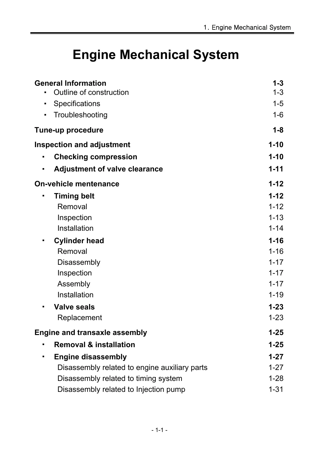
- 1. Engine Mechanical System
- Outline of Construction and Technical Specifications
- Troubleshooting Guide and Engine Tune-up Procedures
- Compression Pressure Testing and Valve Clearance Adjustment
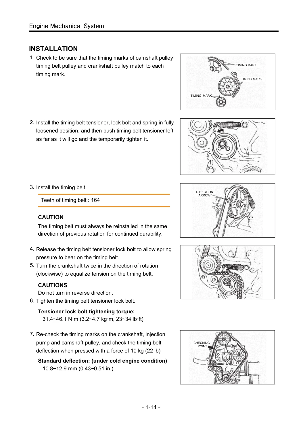
- On-Vehicle Maintenance: Timing Belt Removal, Inspection, and Installation
- Cylinder Head Removal, Disassembly, Inspection, and Installation
- Valve Guide, Valve Stem, and Valve Seal Replacement
- Engine and Transaxle Assembly Removal and Installation
- Full Engine Disassembly: Auxiliary Parts, Timing System, and Injection Pump
- Disassembly: Cylinder Head, Lubrication System, Flywheel, Pistons, and Rods
- Inspection and Repair: Cylinder Head Flatness, Camshaft, and Valve Recession
- Inspection and Repair: Cylinder Block Flatness, Cylinder Bores, and Pistons
- Inspection and Repair: Connecting Rods, Bushings, Crankshaft, and Bearings
- Engine Reassembly: Valves, Springs, Tappets, and Adjusting Discs
- Engine Reassembly: Pistons, Rings, Connecting Rods, and Oil Jets
- Engine Reassembly: Crankshaft, Main Bearings, and Thrust Bearings
- Installation: Oil Pump, Strainer, Baffle Plate, Oil Pan, and Rear Cover
- Installation: Flywheel, Clutch Cover, Pulleys, and Cylinder Head Assembly
- Torque-Angle Cylinder Head Tightening and Camshaft Fitting
- Installation: Water Pump, Thermostat, Fan Bracket, and Manifolds
IMAGES PREVIEW

- 2. Lubrication System
- Outline of Construction and Lubrication Flow Chart
- Lubricating System Specifications and Viscosity Standards
- Troubleshooting Guide: Oil Pressure Drop and Warning Lamp Illumination
- Oil Pressure Testing and Verification at 3,000 RPM
- Oil Filter and Oil Bypass Filter Replacement Procedures
- Oil Pan, Baffle Plate, and Strainer Service
- Oil Pump Assembly: Removal, Disassembly, Inspection, and Reassembly
- Oil Pump Gear Tip, Side, and Body Clearance Measurement
- Water-Cooled Oil Cooler Disassembly, Testing, and Relief Valves
- Piston Cooling Oil Jet and Check Valve Inspection
- 3. Cooling System
- System Description, Structural Views, and Coolant Flow Schematic
- Cooling Specifications: Thermostat Ratings, Cap Relief Pressure, and Fan Data
- Troubleshooting Guide: Overheating, Corrosion, and Coolant Leakage
- Coolant Level Inspection, Leakage Pressure Testing, and Replacement
- Water Pump Removal, Inspection, Disassembly, and Installation
- Thermostat Removal, Two-Stage Temperature Verification, and Installation
- Radiator Removal, Inspection, and Cap Testing
- Cooling Fan Bearing Assembly Overhaul and Pressing Procedures
- 4. Fuel System
- General Description and VE Mechanical Injection Pump Overview
- Fuel System Specifications and Troubleshooting Guide
- Fuel Delivery System: Water Drain, Cartridge Filter, and Air Bleeding
- Water Detector Sensor Continuity and Switch Testing
- Idling Speed and Fast Idling Speed Adjustment
- Injection Timing Inspection (2° BTDC) and Dial Gauge Cam Lift Measurement
- Injection Pump Timing Adjustment and Cam Lift Verification
- Injection Pump Removal, Woodruff Key Alignment, and Installation
- Fuel Cut Valve Electrical Inspection and Replacement
- Injection Nozzle Removal, Disassembly, and Overhaul
- Injection Nozzle Testing: Pop Pressure, Seat Tightness, and Spray Pattern
- Nozzle Starting Pressure Adjustment via Precision Shims
- Accelerator Linkage Deflection and Full-Travel Stopper Adjustment
- 5. Engine Electrical System
- Starting System Specifications and Starter Motor Tightening Torques
- Charging System Specifications and Alternator Output Ratings
- Alternator Description, Terminal Operations (B, L, R), and Self-Diagnostics
- Alternator In-Vehicle Testing: No-Load Voltage and Full Output Current
- Alternator Bench Overhaul, IC Regulator Separation, and Diode Testing
- Battery Safety, Electrolyte Inspection, and Specific Gravity Tables
- Starter Motor Removal, Installation, and Bench Disassembly
- Starter Component Testing: Magnetic Switch, Brushes, Yoke, and Commutator
- Armature Runout, Segment Depth, and Overrunning Clutch Inspection
- Starter System Troubleshooting Workflows (Cranking Faults)
- Quick Start System (QSS) Preheating Schematic and Operating Phases
- QSS Troubleshooting Flowchart: Relay Cycling and Control Unit Checks
- Glow Plug Relay Bench Testing and Glow Plug Continuity Verification
- Glow Plug Replacement and Complete Engine Electrical Wiring Diagrams
Together, these comprehensive chapters equip technicians with complete factory workshop procedures, precise measurement charts, and troubleshooting routines covering every moving part and auxiliary system of the engine assembly.
Detailed Engine Mechanical & Overhaul Specifications
Rebuilding the 2184 cc engine demands strict adherence to the manufacturer dimensions published in the Ford R2 Diesel Engine Workshop Manual. The overhead camshaft direct-drive valvetrain operates with bucket tappets and interchangeable adjusting discs, eliminating rocker arms and pushrods for improved high-rpm stability. The manual specifies cold valve clearances of 0.20 to 0.30 mm (0.008 to 0.012 in) for intake valves and 0.30 to 0.40 mm (0.012 to 0.016 in) for exhaust valves. Tappet shims are detailed in 37 distinct thickness increments ranging from 3.400 mm to 4.600 mm, allowing precise lash setting using special service tappet holder OK011 120 007.
The aluminum cylinder head requires exact bolt torque-angle tightening to ensure durable gasket clamping across the 22.9:1 compression ratio. Cylinder head bolts must be checked against the maximum length limit of 114.5 mm (standard length 112.7 to 113.3 mm). The tightening process mandates an initial torque of 3.0 kg-m (21.7 lb-ft) across the numbered sequence, followed by two successive 90-degree (90° to 105°) angle turns based on painted reference marks. Cylinder bore standards are maintained at 86.00 mm (wear limit 86.17 mm), with connecting rod bend and twist tolerances capped at 0.16 mm per 100 mm. Crankshaft main journals (59.97 to 59.96 mm diameter) and crank pins (50.94 to 50.955 mm diameter) include full plastigauge oil clearance specifications (main bearings: 0.031 to 0.050 mm; connecting rod bearings: 0.03 to 0.06 mm), supported by 0.25 mm, 0.50 mm, and 0.75 mm undersize bearing sizing tables.
Fuel Injection Calibration & Electrical Diagnostics
Fuel delivery on the Ford R2 engine is managed by a mechanical distributor-type VE injection pump driven directly by the 164-tooth timing belt. The Ford R2 Diesel Engine Workshop Manual outlines exact procedures for checking and adjusting static injection timing to 2° BTDC. By inserting a metric dial gauge into the pump hydraulic distributor head plug, technicians measure plunger stroke lift (specified at 1.0 ± 0.02 mm at 2° BTDC, with a total maximum cam lift of 2.2 mm). Throttle-type injection nozzles are tested on a bench tester for an opening pressure of 135 kg/cm² (1919.7 psi), with adjustments performed via 27 shim thickness selections from 0.50 mm to 1.54 mm in 0.04 mm steps.
Electrical troubleshooting covers the complete charging and preheating network. The manual outlines diagnosis of the 60-amp alternator equipped with an integral rear-mounted vacuum pump, including internal IC regulator testing and field coil continuity. The starting system section details complete disassembly and runout limits for the 2.0 kW direct-drive starter motor. Cold starting is governed by the Quick Start System (QSS), combining pre-heating (7-second glow plug energization), chopping (continuous heating during cranking), and a 15-second after-glow cycle when coolant temperatures are below 30°C (86°F). Complete diagnostic tables and schematic diagrams guide technicians through relay testing, water temperature switch verification, and glow plug replacement.
Professional Shop Utility and Instant PDF Delivery
This Ford R2 Diesel Engine Workshop Manual equips mechanics, automotive machine shops, and vehicle restorers with verified manufacturer instructions to carry out total engine rebuilds, timing belt renewals, injector testing, and electrical repairs with complete confidence. By adhering to factory torque figures, journal wear limits, and angle-tightening sequences, you safeguard the engine against head gasket failure, bearing seizure, and improper injection timing. The manual is delivered as an instant digital PDF download immediately upon checkout. Compatible with desktop computers, laptops, tablets, and smartphones, the file can be browsed digitally in the shop or printed out for clear reference right at the repair bench.
Reviews
There are no reviews yet.