
FPT Cursor 13 TE2A TE3A G-Drive Power Generation Technical Repair Manual
Original price was: $34.95.$19.95Current price is: $19.95.
Complete FPT Cursor 13 TE2A and TE3A G-Drive technical repair manual for power generation applications. Covers the F3BE0685A engine from general information and operating diagrams through full mechanical overhaul, EDC 7 UC31 electronics, scheduled maintenance and tightening torques.
Description
FPT Cursor 13 TE2A TE3A G-Drive Technical Repair Manual
This is the full technical repair manual for the FPT Cursor 13 Series engine in G-Drive power generation configuration, covering the CURSOR 13 TE2A and CURSOR 13 TE3A power units built on the F3BE0685A engine platform. It is the working document used by repair technicians to carry out overhaul, component removal and refitting, electrical diagnostics, scheduled servicing and specification checks on these 6-cylinder 12.88 litre generator-drive engines.
The manual is organised into nine sections plus an appendix, moving from general engine information and system operating diagrams through to full mechanical overhaul of the crankcase, cylinder head, crankshaft, connecting rod and piston assemblies. Every stage carries the tightening torques, assembly clearances, measurement values and special tool references needed to complete the job to the manufacturer’s specification.
File Details
- Manual type: Technical Repair Manual
- Brand: FPT (Fiat Powertrain Technologies)
- Series: CURSOR 13 Series – Power Generation Application
- Models covered: CURSOR 13 TE2A, CURSOR 13 TE3A (G-Drive configuration)
- Engine platform: F3BE0685A
- Document number: P4D32C1002 E
- Edition date: February 2007
- Language: English
- Format: PDF
- Page count: 192 pages
Chapters Covered
- Introduction – general information, symbols, warnings, service operations, conversion tables
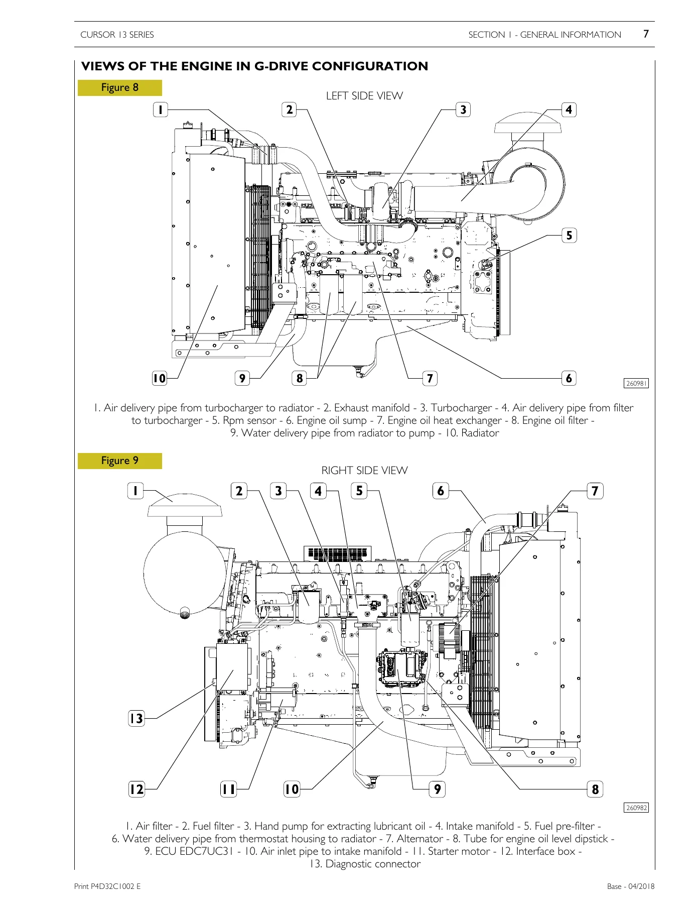
- Section 1 – General information: technical/commercial code correspondence, views of the engine not outfitted, views of the engine in G-Drive configuration, main features
- Section 2 – Operating diagrams: Supply (fuel system diagram, overpressure valve, feed pump, pump injector, injector phases, heated settling vessel pre-filter, fuel filter)
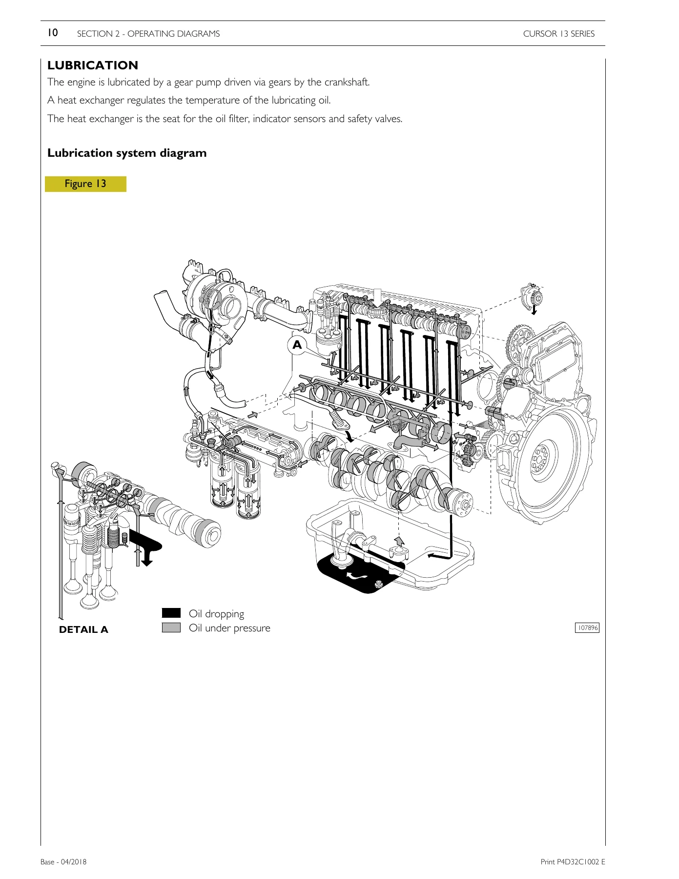
- Section 2 – Lubrication: lubrication system diagram, oil pump, overpressure valve, oil pressure regulator valve, heat exchanger, by-pass valve, thermostatic valve, engine oil filters
- Section 2 – Cooling: description, operation, engine cooling system diagram, water pump, thermostat
- Section 2 – Turbocharging: turbocharging diagram, HOLSET HX60W turbocharger
- Section 3 – Electrical equipment: perspective view, EDC 7 UC31 electronic control unit, engine cable, EDC control unit pinout, pump injector, coolant temperature sensor, fuel temperature sensor, crankshaft rpm sensor, timing sensor, oil pressure and temperature sensor, air pressure and temperature sensor, alternator, starter motor, EDC system functions, interface housing, connector J1, wiring from engine interface, PT-BOX diagnostics connection
- Section 4 – Scheduled maintenance: maintenance planning, inspections and maintenance interventions, oil table, recommended oil temperature range, extra plan operations, maintenance procedures, checks, periodic maintenance, extraordinary maintenance
- Section 5 – Removal and assembly of the engine: removal and refitting of the outfitted engine, placing the engine on the stand, removal of components for general mechanical overhaul, component assembly part 1 and 2, engine timing (flywheel assembly, camshaft fitting, pump-injector fitting, rocker arm shaft fitting, camshaft timing, phonic wheel timing, valve clearance adjustment and rocker pre-loading)
- Section 6 – General mechanical overhaul: engine overhaul and disassembling, repair operations, cylinder block checks and measurements, cylinder liners, crankshaft, main journal and crankpin measurement, main and big end bearing shell selection, timing and oil pump control gear replacement, assembly clearance checks, crankshaft thrust clearance, engine assembly, connecting rod-piston assembly, piston rings, connecting rod, bushings, cylinder head, valves, valve seats, valve guides, injector sleeves, camshaft, rocker shaft, timing gears
- Section 7 – Technical specifications: assembly clearance data, tightening torques
- Section 8 – Tools: FPT diagnostics equipment, special tool references
- Appendix – Safety regulations: standard safety precautions, accident prevention, protection of the environment
Across these sections the manual gives a technician the complete picture of the Cursor 13 TE2A / TE3A G-Drive engine: how the fuel, lubrication, cooling and turbocharging circuits are laid out and how they behave; how the Bosch EDC 7 UC31 control unit is wired, pinned out and diagnosed; what has to be checked and replaced at each service interval; how to remove and refit the engine from the G-Drive package; and how to strip, measure, select bearings for and rebuild the crankcase, crankshaft, connecting rods, pistons, cylinder head and timing system to the values the manufacturer specifies.
Fuel, Lubrication, Cooling and Turbocharging Systems
Section 2 is dedicated to how the engine actually works. The fuel section walks through the supply circuit with a numbered system diagram, then breaks down each component in turn – the overpressure valve calibrated to 0.2–0.3 bar on the return pipe, the feed pump with its 5–8 bar pressure relief valve, the pump injector and the four phases of injection (filling, begin of injection, pressure reduction and the return path to the cylinder head). It also covers the heated settling vessel pre-filter with its 270 ml water accumulation capacity and the main fuel filter.
The lubrication chapter documents the gear pump, the safety valve spring data, the pressure relief valve opening at 5 bar, the heat exchanger with its nine elements, the by-pass valve opening at 3 bar and the thermostatic valve start of opening at 82 ± 2 °C with 8 mm travel at 97 °C. The cooling chapter describes the forced-circulation closed-circuit system, the water pump, the thermostat and the coolant flow path. The turbocharging chapter documents the HOLSET HX60W turbocharger with its wastegate pressure relief valve.
Electrical Equipment and EDC 7 UC31 Diagnostics
Section 3 covers the engine’s electrical architecture in detail. It includes the EDC 7 UC31 electronic control unit with its three connector groups (electro-injectors, chassis and sensor), the engine wiring perspective, the full EDC control unit pinout tables for both the sensor connector and the injector connector, and the pinout of the engine interface housing connectors J1, J2, J3, J7 and J9.
Individual sensor sections cover the coolant temperature sensor with its NTC characteristic and pin 15/26 ECU connection, the fuel temperature sensor at pins 17/35, the crankshaft rpm sensor (BOSCH, 8 ± 2 Nm, pins 19/23), the timing sensor (BOSCH, 8 ± 2 Nm, 880–920 Ω, pins 9/10), the oil pressure and temperature sensor and the air pressure and temperature sensor. Alternator and starter motor diagrams and pinouts are included, together with the EDC system function descriptions – fuel injection, cylinder balancing, delivery correction based on water temperature, derating on overheating, synchronization search and cold start behaviour.
Scheduled Maintenance
Section 4 lays out the maintenance plan for these G-Drive generator engines: daily checks of engine oil level, coolant level and heat exchanger cleanliness; water drainage from the fuel pre-filter at 150 hours; monthly air filter inspection; six-monthly battery electrolyte and exhaust duct checks; oil and filter changes at 600 hours or 12 months; fuel filter and pre-filter replacement; air filter replacement at 1200 hours or 2 years; coolant replacement; blow-by filter element replacement; ancillary belt change; turbocharger inspection and tappet clearance checks at 2400 hours. The oil table sets out the viscosity and specification requirements by ambient temperature, and the fluid capacities table lists the engine and G-Drive coolant and oil capacities.
Engine Removal, Timing and Mechanical Overhaul
Section 5 covers removal and refitting of the outfitted G-Drive engine, placing the engine on the rotating stand, and removal of components for general overhaul. The engine timing chapter then covers the flywheel assembly with its punch-mark hole references for TDC of each piston pair, camshaft fitting with the reference marks, fitting of pump-injectors, rocker arm shaft fitting with the 80 Nm plus 60° tightening sequence, camshaft timing via the cam lift value of 4.44 ± 0.05 mm, phonic wheel timing, and the intake/exhaust valve clearance adjustment (intake 0.40 ± 0.05 mm, exhaust 0.60 ± 0.05 mm) together with the pump injector rocker pre-load of 5 Nm plus 1/2 to 3/4 turn back.
Section 6 is the full mechanical overhaul. It contains cylinder liner measurement and protrusion checks (0.045–0.075 mm), liner replacement, crankshaft main journal and crankpin measurement, the class-based selection of main and big end half-bearings by colour (red, green, yellow, red/black, green/black, yellow/black) and by standard or undersize status (-0.127, -0.254, -0.508), assembly clearance verification with calibrated wire, crankshaft thrust clearance checking, the lower crankcase tightening sequence (30 Nm outer, 120 Nm + 60° + 55° inner, then 60° on the outer), connecting rod and piston disassembly, piston diameter and gudgeon pin measurement, piston ring end gap checks, connecting rod alignment checks (parallelism, torsion and bending to 0.08 mm), cylinder head valve removal, valve stem and guide measurement, valve seat regrinding and replacement, injector sleeve removal and refitting with the special tooling, camshaft measurement and bush replacement, and rocker arm and rocker shaft inspection and dimension checks.
Technical Specifications and Tightening Torques
Section 7 gathers the assembly clearance data and tightening torques into structured tables: cylinder liner housing and liner dimensions, piston and pin measurements, piston ring slot and end gap values, connecting rod small end and big end bearing seats, crankshaft journal diameters and half-bearing thicknesses, main bearing bore classes, crankshaft end float, camshaft journal and bush dimensions, rocker arm bush and shaft values, valve guide and seat dimensions, valve spring data at closed and open, injector protrusion and camshaft cam lift values.
The tightening torque tables cover the lower crankcase to crankcase joint, piston cooling nozzle filler, heat exchanger, suction rose, oil sump spacer, gear casing, control unit mounting, cylinder head bolts (60 Nm pre-tighten, 120 Nm pre-tighten, then 90° and 65° angle), rocker arm shaft, injector brackets, camshaft gear, impulse wheel, exhaust manifold, connecting rod cap bolts, engine flywheel, damper flywheel, intermediate gear pins, oil pump, fuel pump mount, turbocharger, water pump, belt tensioners, starter motor, air heater, alternator, sensors and the injector electrical connections.
Special Tools and Diagnostics
Section 8 lists the FPT diagnostics equipment – the PT-Plus tool variants for Italian, English, UK, French and German markets, the interface, cables and pre-paid card – and the full range of special service tools referenced throughout the repair procedures: rotary stand, crankshaft seal extractors, injector sleeve puller, crankshaft gasket keys, valve guide drifts, valve removal and installation plates, flywheel rotation and retention tools, cylinder liner protrusion and extraction tooling, camshaft bush drift, crankshaft lifting tool, rocker arm shaft fitting tool, engine TDC positioning tool, phonic wheel timing tool, cylinder liner check tool, engine brackets for the rotating stand, injector sleeve cold-heading tool, timing check tool, dial gauge stands, valve guide sleeker, injector sleeve deposit removal tool, and the cutter and guide bushes used for refacing the injector seat.
What This Manual Lets You Do
With the FPT Cursor 13 TE2A TE3A G-Drive Technical Repair Manual in hand, a qualified technician can correctly diagnose and repair the F3BE0685A engine as fitted to a G-Drive generating set. That means stripping and rebuilding the engine to the correct clearances and torques, selecting the right main and big end half-bearings from the crankshaft and crankcase class markings, setting camshaft and phonic wheel timing correctly, adjusting valve clearances and injector rocker pre-load to specification, diagnosing the EDC 7 UC31 control system with the correct pinouts and sensor values, and following the manufacturer’s scheduled maintenance intervals for the G-Drive package.
Working from the correct procedures and specification values matters on an engine like this because bearing clearances, timing values, tightening angles and torque figures are all interdependent – getting one wrong costs far more than the manual. Every figure in these pages is the one the manufacturer published for this specific engine platform.
IMAGES PREVIEW
Delivered as an instant PDF download after payment. No shipping, no waiting. Read it on a laptop, tablet or phone in the workshop, and print the pages you need for the job at hand.
Reviews
There are no reviews yet.