
FPT Cursor Series Tier 4B Stage IV F3HFE613 Technical Repair Manual – F3HFE613B/D B010 B011 PDF
Original price was: $39.95.$23.95Current price is: $23.95.
Complete FPT Cursor Series Tier 4B Stage IV technical repair manual for F3HFE613BB010, F3HFE613DB010, F3HFE613BB011 and F3HFE613DB011 industrial engines. Covers removal-refitting, general mechanical overhaul, EDC 17 hp 41 electrical systems, ATS/SCR aftertreatment, scheduled maintenance, specifications, tightening torques and special tools.
Description
FPT Cursor Series Tier 4B Stage IV F3HFE613 Technical Repair Manual
This FPT Cursor Series Tier 4B Stage IV F3HFE613 Technical Repair Manual covers the F3HFE613BB010, F3HFE613DB010, F3HFE613BB011 and F3HFE613DB011 industrial 6-cylinder diesel engines. It is the same reference document issued under FPT document number P2D32C011 E, with the base edition dated October 2014. Whether you are diagnosing a rail pressure fault, adjusting tappet clearances, overhauling the crankshaft, or replacing an AdBlue dosing module, this F3HFE613 repair manual provides the procedures, clearances and torque values needed to complete the job correctly.
File Details
- Manual type: Technical repair manual (workshop-level)
- Brand / Manufacturer: FPT Industrial S.p.A.
- Series: Cursor Series Tier 4B / Stage IV
- Engine models covered: F3HFE613BB010, F3HFE613DB010, F3HFE613BB011, F3HFE613DB011
- Commercial codes: CI3 ENT Z W (Tier 4B), CI3 ENT L W (Stage IV)
- Language: English
- File format: PDF
- Document number: P2D32C011 E
- Base edition: 10/2014
Chapters Covered
- Introduction — General information, symbols and warnings, grounding and screening, unit conversions, page header/footer interpretation
- Section 1 — General information: Identification data, correspondence between technical and commercial codes, product technical code, product commercial code, engine views, power-torque curves, engine characteristics
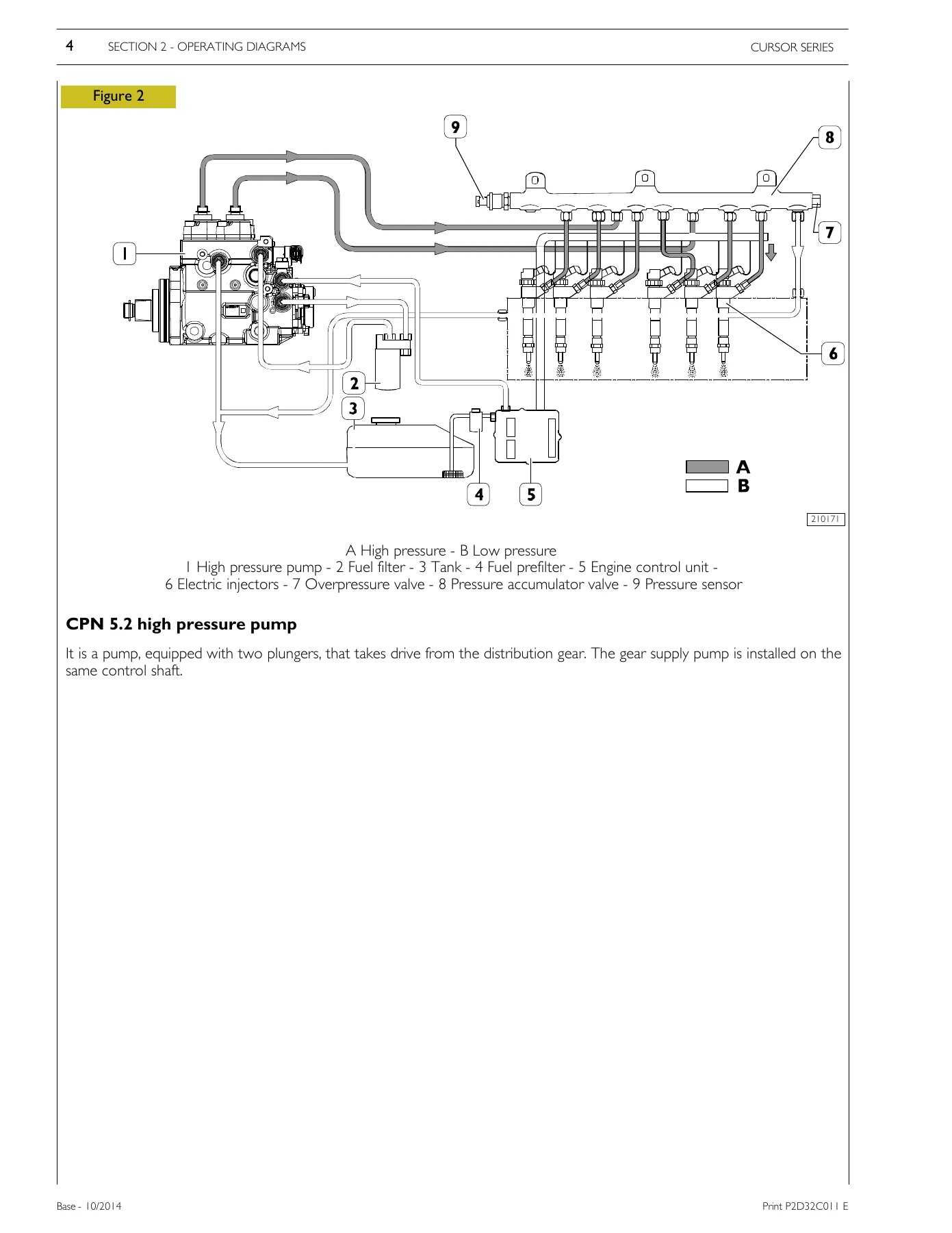
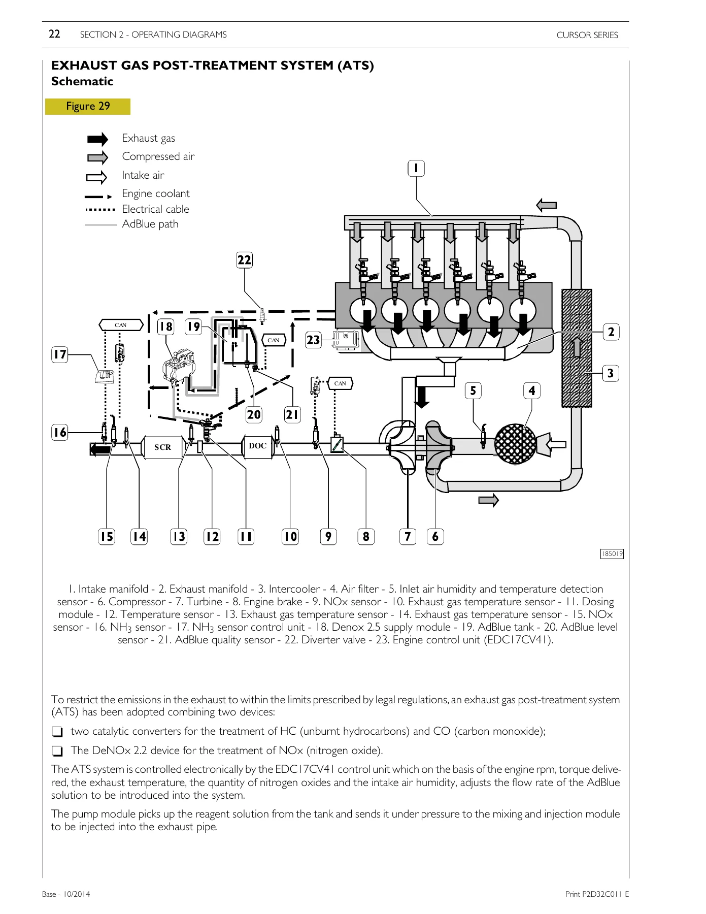
- Section 2 — Operating diagrams: Power supply (CPN 5.2 high pressure pump, pressure limiter valve, fuel filter), lubrication (oil pump, safety valve, oil pressure regulator valve, heat exchanger, filter by-pass valve, engine oil filter, piston cooling nozzle valve, blow-by oil vapour recirculation), cooling (water pump, thermostat), sensors, turbocharger, exhaust gas post-treatment system (ATS) with AdBlue specifications, DeNOx 2.2 supply module, DeNOx 2.5 dosing module, diverter valve, NH3 sensor, NOx sensor, exhaust gas temperature sensor, humidity sensor, scheduled ATS maintenance
- Section 3 — Electrical equipment: Vehicle side wiring, engine side wiring, PIN OUT connector IB and IA (96-pin EDC 17 HP 41 control unit), CRIN injector 3.3, rail pressure sensor (RSD 4), crankshaft pressure sensor, exhaust gas pressure sensor (P3), crankshaft sensor, camshaft sensor, fuel temperature sensor, coolant temperature sensor, oil pressure and temperature sensor, turbocharging air pressure and temperature sensor, fuel pre-filter clogged sensor, fuel filter clogged sensor, alternator, electric starter motor
- Section 4 — Scheduled maintenance: Checks during periods of use (engine lubricant oil level, coolant level, visual inspection, draining water from fuel prefilter, ancillary belt tension and condition, exhaust duct inspection), periodic maintenance (engine lubricant oil change, engine oil filter replacement, fuel prefilter replacement, fuel filter change, ancillary belt replacement, turbocharger connection pipes and wastegate linkage check, turbocharger lubricant pipe tightness, turbocharger gasket seal check, blow-by filter element replacement), unscheduled maintenance (tappet clearance check and adjustment, engine coolant change)
- Section 5 — Removal-refitting of the main engine components: Ancillary belt, alternator, water pump, thermostat case, electric starter motor, engine cable, turbocharger, oil filter, heat exchanger, oil sump, fuel filter, fuel system bleeding, common rail, control unit, blow-by, head cover, electro-injector wiring, electro-injector, intake manifold, exhaust manifold, cylinder head
- Section 6 — General mechanical overhaul: Engine disassembling, removal of front suspension mounts, damper flywheel, alternator water pump drive belt, pulley, water pump, thermostat case, crankshaft front gasket, turbocharger, oil filter, heat exchanger, starter motor, intake manifold, blow-by case, blow-by filter, timing gear cover, head cover, fuel filter, high pressure pump, engine flywheel, crankshaft rear gasket, engine mounts, flywheel case, double gear, connecting rod, oil pump, rocker arm shaft, rail, injector, camshaft, cylinder head, oil sump, suction strainer, lower crankcase, crankshaft, main bearings, oil sprayers; comprehensive crankcase checks; cylinder liners removal/refitting and protrusion check; crankshaft measurements; main half-bearings shim; measuring main journals and crankpins; defining diameter class for half-bearings; selection of main half-bearings; checking oil pump and timing control gear; crankshaft end float; crankpin fitting clearance; overhaul of connecting rod-piston assembly; piston rings removal; piston and pin diameter measurement; pin-piston coupling conditions; seal rings measurement; connecting rod checks; axis alignment, torsion and bending checks; small end bushing check; piston assembly; fitting piston rings; cylinder head overhaul; valve removal/descale/check; regrinding and replacing valve seats; replacing valve guides; injector protrusion check; valve spring check; valve assembly; mounting oil seal ring; timing system assembly; cam lift and camshaft journals alignment; camshaft bushes check; rocker shaft check; intake valve rocker arms check; engine assembly; oil sprayer assembly; main bearings assembly; crankshaft assembly; lower crankcase assembly; connecting rod-piston assembly in cylinder liners; crankshaft front and rear gasket installation; cylinder head assembly; installing oil pump; fitting camshaft; high pressure pump assembly; intake and exhaust rocker arm clearance adjustment; tappet cover assembly; fuel filter assembly; timing gear assembly cover mounting; blow-by filter fitting; blow-by case fitting; suction strainer installation; oil sump assembly; inlet manifold assembly; starter motor assembly; heat exchanger assembly; oil filter assembly; turbocharger assembly; exhaust manifold assembly; thermostat case assembly; water pump assembly; pulley assembly; alternator assembly; alternator/water pump drive belt assembly; damper flywheel installation; oil pressure adjustment valve assembly; fitting front suspension mounts
- Section 7 — Technical specifications: Main features, data and installation clearances, tightening torques
- Section 8 — Tools: Complete special tool list with FPT tool numbers
- Appendix — Safety regulations: Standard safety precautions, accident prevention, during maintenance, protection of the environment
Across its sections this F3HFE613 workshop manual takes a technician from initial identification and layout views through the fuel, lubrication, cooling, turbocharging and aftertreatment systems, then into the electrical architecture of the EDC 17 HP 41 control unit, the scheduled servicing intervals, the full component removal and refitting sequence, and finally the bench-level mechanical overhaul with measurements, selection tables for half-bearings and complete torque data. It is a working reference for both routine service and major repair of these Tier 4B / Stage IV Cursor engines.
What This Manual Enables You to Do
With this FPT Cursor F3HFE613 technical repair manual on hand you can carry out the full range of service and repair tasks on the F3HFE613B and F3HFE613D engines: diagnose rail pressure and injector faults using the pin-out and sensor data, replace the high pressure pump and electro-injectors with the correct torque sequence, adjust tappet clearances and injector pre-loading, remove and refit the cylinder head with the staged tightening angles, overhaul the crankshaft and select the correct main and big-end half-bearings from the diameter class tables, service the ATS/SCR system including filter replacement and dosing module diagnostics, and follow the scheduled maintenance intervals for oil, filters, belts and coolant. The F3HFE613BB010, F3HFE613DB010, F3HFE613BB011 and F3HFE613DB011 variants are all covered, so the same document serves the entire Cursor 13-litre Tier 4B / Stage IV industrial family.
Correct procedures and factory torque values matter on these engines — the cylinder head uses a four-stage torque-plus-angle sequence, the connecting rod cap uses 70 Nm plus 60 degrees, the engine flywheel uses 120 Nm plus 90 degrees, and the lower crankcase uses a staged 160 Nm plus twin 60-degree sequence. Getting these wrong risks warped heads, stretched bolts or bearing failure. This F3HFE613 repair manual gives the exact figures, tightening orders and clearance limits so the job is done once and done right.
IMAGES PREVIEW
Delivered as an instant PDF download after payment — no shipping, no waiting. Read it on a laptop, tablet or phone in the workshop, print only the pages you need for the job at hand, and keep the full manual on file for every future service. Whether you are an independent workshop, a fleet maintenance technician or an owner-operator looking after a Cursor Tier 4B engine, this technical repair manual is the reference you will reach for.
Reviews
There are no reviews yet.