
GE Security EST3 Fire Alarm System Installation and Service Manual – Rev 7.0 PDF
Original price was: $39.95.$24.95Current price is: $24.95.
Complete GE Security EST3 Installation and Service Manual, P/N 270380 Rev 7.0 (10SEP07). Covers system overview, installation, wiring, power-up and testing, preventive maintenance, service and troubleshooting, plus security, access control, and centralized audio applications for EST3, EST3R, EST3-230 and EST3R-230 panels.
Description
This is the full GE Security EST3 Installation and Service Manual, document P/N 270380, Revision 7.0, dated 10SEP07. It is the technical reference for installing, wiring, powering up, testing, and servicing the EST3 integrated life safety system, and it applies to the EST3, EST3R, EST3-230, and EST3R-230 models. Revision 7.0 was issued to conform to UL 864 9th edition requirements, so the field-programmable options, NAC signal synchronization rules, and listing restrictions shown here reflect that edition of the standard.
File Details
- Manual type: Installation and Service Manual
- Brand / manufacturer: GE Security, Inc.
- Document number: P/N 270380
- Revision: Rev 7.0, dated 10SEP07
- Applies to: EST3, EST3R, EST3-230, EST3R-230
- Language: English
- File format: PDF
- Page count: Approximately 400 pages, including eight chapters, Appendices A through C, a glossary, and an index
- Coverage: Hardware installation, field wiring, network and audio risers, security and access control, centralized audio, power-up, acceptance testing, preventive maintenance, and troubleshooting
Chapters Covered
- Chapter 1 — System overview: system description and features, minimum system requirements, system construction, audio subsystem description, network audio riser wiring, amplifiers and backup amplifiers, 3-ASU Audio Source Unit, firefighter phone, digital network subsystem, network data riser wiring (Class A and Class B), download connections, foreign language support, Signature series devices, network applications and feature/function domains, audio applications and audio channels, manual audio zone selection, messages
- Chapter 2 — Security applications: security equipment, control panel and Signature Controller module, SIGA-MD Motion Detector, SIGA-SEC2 Security Loop module, 3-SAC Security Access Control module, SAC bus, KPDISP Keypad Display, 3-MODCOM Modem Communicator, RPM and KDC programs, certificate installations, multiple 3-MODCOM modules, multiple site security and access, multiple tenant security, secure access
- Chapter 3 — Access control applications: access control equipment, CRC Card Reader Controller and CRC options, input circuits, output circuit, card readers, locks, anti-passback (strict, logged, timed), central monitoring station reporting, common door access, delayed egress, elevator control, emergency exit door, handicap access door, maglock peripherals, multiple card readers, muster, power for continuous locks, power for intermittent locks, power from an AC source, power from a remote source, remote controls, two-person rule
- Chapter 4 — Centralized audio applications: equipment required, ATPC Amplifier Terminal Panel Cabinet, RKU equipment racks, ATP Amplifier Terminal Panel, battery backup, Dukane 125 W and 250 W audio amplifiers, URSM Universal Riser Supervisory Module, ATP external battery charger, amplifier backup, branch speaker wiring, troubleshooting
- Chapter 5 — Installation: installation overview, electrostatic discharge and energized system precautions, circuit compatibility, recommended cable manufacturers, UL 864 NAC signal synchronization, typical circuits, creating an initial startup version of the project database, system installation sequence, preliminary field wiring testing, chassis installation in EIA 19-inch racks, ATCK Attack Kit, local rail module installation, 3-MODCOM, 3-SAC, 3-AADC1 and IRC-3, AC power and DC battery wiring, auxiliary/booster power supplies, PT-1S impact printer, adjusting amplifier output levels, CDR-3 Zone Coder, external modem for the Remote Diagnostics Utility, running the RPM and distributing profiles
- Chapter 6 — Power-up and testing: cabinet power-up procedure, runtime and system errors, initial and reacceptance test procedures, control and emergency communications equipment testing, detector, input module and output module testing, initiating device testing, notification appliance testing, Record of Completion
- Chapter 7 — Preventive maintenance: general requirements, preventive maintenance schedule, Signature device routine maintenance tips, Signature detector cleaning procedure, system trouble and maintenance log
- Chapter 8 — Service and troubleshooting: maintenance philosophy, problem classification, hardware problems, modules, audio components, pseudo point descriptions, Signature data circuit (SDC) operation, basic SDC troubleshooting, Signature controller modules, device troubleshooting, Signature diagnostic tools, DSDC status, addressable analog diagnostic tools, 3-AADC1, addressable analog device troubleshooting, wiring problems
- Appendix A — System addresses: address format, LRM addresses, control/display module addresses, device addresses
- Appendix B — System calculations: network data riser limits, Signature data circuit wire length, notification appliance circuit calculations, 25 or 70 Vrms NAC wire length, addressable analog circuit wire length, cabinet battery, SAC bus power, CPU memory, fiber optic cable worksheet
- Appendix C — Listing requirements: NFPA standards, minimum requirements for UL security applications, UL and ULC requirements
Taken as a whole, this EST3 Installation and Service Manual gives a certified technician the complete build sequence for an EST3 network — from locating and installing the cabinet chassis and local rail modules, through AC and battery wiring, field wiring verification, and database download, all the way to acceptance testing and the Record of Completion. It also carries the engineering data behind the field work: system address formats, wire length and capacitance limits, notification appliance circuit calculations, battery sizing, and SAC bus power budgets. The troubleshooting half of the manual is built around pseudo point descriptions and diagnostic tables, so faults can be traced from the LCD message back to the module, circuit, or device that produced it.
Installation, Power-Up, and Acceptance Testing
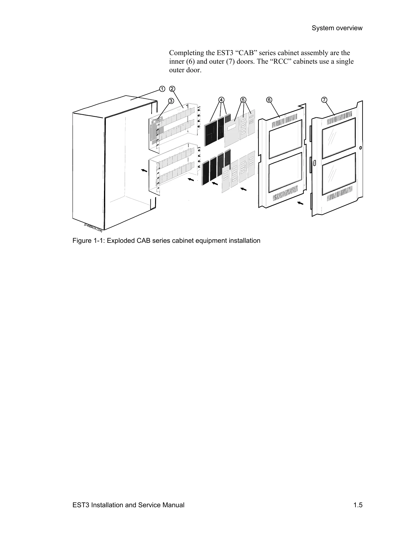
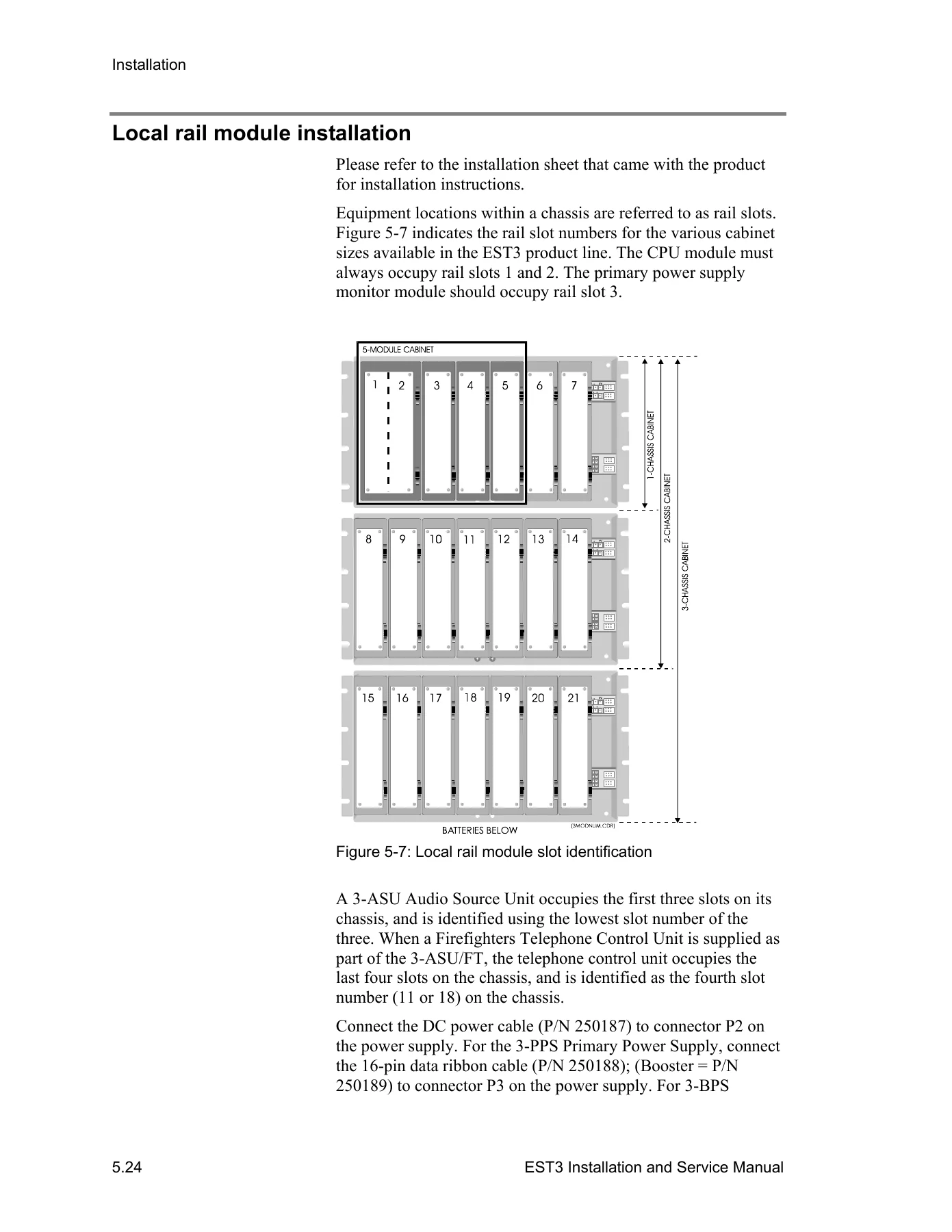
The installation chapter covers the practical detail that generic panel documentation leaves out. It shows how the EST3 cabinet assembles in layers — backbox, rail chassis assemblies, rail modules, and control/display modules — and how those layers map to the rail slot numbering used by the System Definition Utility, with the CPU occupying slots 1 and 2 and the primary power supply monitor module in slot 3. It walks through the local rail module installation sequence, option card seating, display ribbon cable routing, and the snap rivet fastening that locks each module to the rail.
Field wiring is handled with actual expected meter readings. The preliminary field wiring testing tables list the resistance values a technician should see across addressable analog circuits, traditional initiating device circuits, telephone riser circuits, RS-485 communication circuits, and RS-232 communication circuits, including what the reading means when the meter leads are reversed and what an incorrect value points to. The same chapter documents UL 864 NAC signal synchronization requirements and the modules that can and cannot be used to synchronize notification appliance circuits, plus the wiring for the 3-IDC8/4, SIGA-CC1, SIGA-CC1S, and auxiliary/booster supply arrangements.
Power-up and testing follows the same hands-on pattern: cabinet power-up steps, the download order for CPU, 3-ASU, and Signature controller databases, then acceptance tests for primary and booster power supplies, the CPU with LCD module, 3-RS232 and 3-RS485 cards, the 3-IDC8/4, 3-SSDC(1), 3-AADC(1), 3-OPS, 3-ASU, 3-FTCU, 3-ZAxx amplifiers, control/display modules, and the Amplifier Transfer Panel. Each test lists the expected LED, relay, display, and queue behavior so a failed step is obvious. A downloadable Record of Completion form closes out the process.
Security, Access Control, and Centralized Audio Applications
Three full chapters are devoted to applications rather than hardware alone, and each one is built from block diagrams showing the components required and how they interconnect. The security chapter covers the Signature data circuit’s dual role supporting fire and security devices, the SIGA-MD motion detector, the SIGA-SEC2 security loop module, the 3-SAC and its SAC bus, the KPDISP keypad display, and the RPM and KDC tools used to build and distribute the security database. It also lays out certificate installations — Central Station Grade B and Grade C, Grade A Police Station Connect, and Local Mercantile Grade A — with the ATCK Attack Kit, 3-TAMPRCC cabinet tamper switch, local bell, tamper loop, and telephone line supervision each certificate requires.
Access control applications run from the CRC Card Reader Controller outward: anti-passback in strict, logged, and timed forms; delayed egress with the CRCSND sounder, door contact, and maglock; emergency exit doors; handicap access doors with automatic openers and additional readers; maglock peripherals including the passive infrared detector and request-to-exit switch; multiple card readers for visitor and escort or high and low positions; muster reporting; two-person rule; and the power arrangements for continuous locks, intermittent locks, AC transformer supply, and remote DC supply. Elevator floor access, remote control of parking area devices, and central monitoring station reporting through the 3-MODCOM are covered with their command list programming.
Centralized audio applications addresses the Amplifier Terminal Panel Cabinet format used when amplifiers are banked remotely from the panel. It documents RKU enclosure sizes and rack space, the ATP Amplifier Terminal Panel and the 3-ATPINT Interface Card installation, ATP terminal connections and jumper settings, internal versus external battery charging, and the LaMarche external charger wiring used when multiple ATPs share a common battery. Amplifier backup configurations are shown for single and dual channel systems, along with branch speaker wiring using SIGA-CC1, SIGA-CC2, and SIGA-UM modules, and the URSM Universal Riser Supervisory Module for 25 and 70 Vrms riser supervision.
Service, Troubleshooting, and Preventive Maintenance
The service chapter is organized to shorten diagnosis time. It opens with the maintenance philosophy behind the EST3 — fault isolation to the circuit card, then replacement — and the module substitution rules that apply to flash-memory modules such as the CPU, 3-SSDC(1), 3-AADC1, and 3-ASU, where a substitute must be reloaded with the cabinet configuration before it will behave correctly. From there it moves through rail signal voltages, the 3-PPS/M and 3-BPS/M power supply troubleshooting tables, CPU LED states, fiber optic interface diagnostics, control/display module faults, zoned audio amplifier faults, 3-OPS faults, 3-IDC8/4 faults, and the 3-MODCOM LED states used to follow a dialer call from line seizure through handshake, transmission, and acknowledgement.
Pseudo point descriptions carry the local trouble, monitor, and output points for the 3-SAC, CPU, power supplies, 3-ASU, 3-FTCU, 3-ZAxx, 3-MODCOM, CRC, KPDISP, and 3-LDSM, which is what makes the LCD trouble messages actionable rather than cryptic. The Signature data circuit section explains circuit behavior under real service conditions — removing and reinstalling detectors, replacing a device with a different type, map faults, map pending states, and the automatic re-mapping sequence — and then walks through open, short, and ground fault isolation techniques that halve the circuit repeatedly until the faulty device or wire segment is found. A separate set of addressable analog diagnostic tools and tables does the same job for 3-AADC1 circuits, including interpreting communicating, internal fault, device type fault, unexpected fault, duplicate device, communication, open, short, and compatibility fault tables.
Preventive maintenance closes the operational side with a scheduled component table giving test intervals and procedures for manual stations, heat detectors, smoke detectors, waterflow switches, initiating device circuits, remote annunciators, notification appliances, panel LEDs and trouble buzzer, primary and secondary power, panel trouble signals, supervisory initiating devices, and off-premises signal transmission. It includes the Signature detector cleaning procedure using the SIGA-ST cleaning tool and a system trouble and maintenance log.
Get the GE Security EST3 Installation and Service Manual
This GE Security EST3 Fire Alarm System Installation and Service Manual is the document that lets a technician install, commission, and maintain an EST3 network properly rather than by guesswork. Every rail module has a defined slot, every circuit has an expected resistance reading, every pseudo point has a meaning, and every application — security, access control, centralized audio, firefighter phone — has a wiring diagram showing what connects to what. Working without those references on a networked life safety system means chasing phantom troubles, mis-addressing modules, or commissioning a panel that fails acceptance testing.
It supports the full job: planning cabinet and amplifier placement against cabinet capacity and current limits, installing and wiring rail modules and field circuits, downloading databases in the correct order, running initial and reacceptance tests, diagnosing Signature and addressable analog circuits down to a single device, and keeping the system on its preventive maintenance schedule. Whether the task is a single stand-alone cabinet or a 64-cabinet peer-to-peer network, the procedures and calculations are in the same file.
IMAGES PREVIEW
Delivery is instant. The manual arrives as a PDF download immediately after payment — no shipping, no waiting, no physical book to lose on site. Keep it on a laptop, tablet, or phone and open it in the equipment room, print the pages you need for a specific job, and carry the whole reference with you across every cabinet on the network.
Reviews
There are no reviews yet.