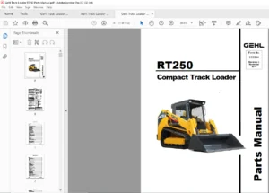
Gehl RT175 RT175 Gen:2/3 RT210 RT210 Gen:2/3 RT250 RT250 Gen:3 Compact Track Loader Service Manual 50940164 – PDF DOWNLOAD
Original price was: $89.95.$29.95Current price is: $29.95.
Gehl RT175 RT175 Gen:2/3 RT210 RT210 Gen:2/3 RT250 RT250 Gen:3 Compact Track Loader Service Manual 50940164 – PDF DOWNLOAD
Description
Gehl RT175 RT175 Gen:2/3 RT210 RT210 Gen:2/3 RT250 RT250 Gen:3 Compact Track Loader Service Manual 50940164 – PDF DOWNLOAD
FILE DETAILS:
Gehl RT175 RT175 Gen:2/3 RT210 RT210 Gen:2/3 RT250 RT250 Gen:3 Compact Track Loader Service Manual 50940164 – PDF DOWNLOAD
Language : English
Pages : 440
Downloadable : Yes
File Type : PDF
Size: 19.9 MB
IMAGES PREVIEW OF THE MANUAL:
DESCRIPTION:
Gehl RT175 RT175 Gen:2/3 RT210 RT210 Gen:2/3 RT250 RT250 Gen:3 Compact Track Loader Service Manual 50940164 – PDF DOWNLOAD
- This manual provides information about the safe and proper operation, maintenance and service procedures for the machine. Major points of safe operation, maintenance and service are detailed in the Safety chapter of this manual.
- This manual also includes general troubleshooting and specification information about the machine. Follow the instructions in the Safety, Operation and Maintenance chapters concerning accident prevention regulations, safety and occupational regulations, and machine and traffic regulations. Manitou Americas is not liable for damage resulting from the failure to follow these regulations.
It is the owner’s or employer’s responsibility to fully instruct each operator in the proper and safe operation and maintenance of the machine. A storage container is provided behind the operator’s seat for storing the Operator’s Manual. After using the manual, return it to the storage container.
- This manual is considered a permanent part of the machine and should be with the machine at all times. If the machine is resold, include this operator’s manual as part of the sale. Replace this manual promptly if it becomes damaged, lost or stolen.
- Some illustrations in this manual may show doors, guards and shields open or removed for illustrative purposes only. BE SURE all doors, guards and shields are in their proper operating positions BEFORE starting the engine to operate the machine. Because of ongoing product improvements, information included in this manual may not exactly match the machine. Manitou Americas reserves the right to modify and improve products at any time without notice or obligation.
TABLE OF CONTENTS:
Gehl RT175 RT175 Gen:2/3 RT210 RT210 Gen:2/3 RT250 RT250 Gen:3 Compact Track Loader Service Manual 50940164 – PDF DOWNLOAD
Introduction………………………………………………………………………………………………………………………………. 13
Safety Symbol………………………………………………………………………………………………………………………….. 13
Contents and Use of this Manual………………………………………………………………………………………………………….. 13
Safety Symbol and Signal Words…………………………………………………………………………………………………………… 14
Safety Alert Symbol…………………………………………………………………………………………………………………. 14
Signal Words……………………………………………………………………………………………………………………….. 14
Machine Orientation…………………………………………………………………………………………………………………….. 14
Proper Machine Use……………………………………………………………………………………………………………………… 14
Service and Registration………………………………………………………………………………………………………………… 15
Machine Model and Serial Numbers……………………………………………………………………………………………………… 15
Component Serial Numbers…………………………………………………………………………………………………………….. 15
ROPS/FOPS Certification Label……………………………………………………………………………………………………………. 16
Component Identification………………………………………………………………………………………………………………… 17
Fields of Application…………………………………………………………………………………………………………………… 18
Using Attachments………………………………………………………………………………………………………………………. 18
Vibration Information…………………………………………………………………………………………………………………… 19
Vibration Measurement and Actions…………………………………………………………………………………………………….. 19
Vibration Levels……………………………………………………………………………………………………………………. 20
Fire Extinguisher………………………………………………………………………………………………………………………. 20
Manufacturer Information………………………………………………………………………………………………………………… 20
Indicator and Operation Symbols………………………………………………………………………………………………………….. 21
Safety……………………………………………………………………………………………………………………………………. 23
Safety Symbol and Signal Words…………………………………………………………………………………………………………… 23
Safety Alert Symbol…………………………………………………………………………………………………………………. 23
Signal Words……………………………………………………………………………………………………………………….. 23
Mandatory Safety Shutdown Procedure………………………………………………………………………………………………………. 24
Before Starting………………………………………………………………………………………………………………………… 24
During Operation……………………………………………………………………………………………………………………….. 25
Applications with Load-Handling Devices…………………………………………………………………………………………………… 28
Parking the Machine…………………………………………………………………………………………………………………….. 29
Electrical Energy………………………………………………………………………………………………………………………. 29
Maintenance and Service Safety Practices………………………………………………………………………………………………….. 29
Battery Hazards………………………………………………………………………………………………………………………… 31
Fire Hazards…………………………………………………………………………………………………………………………… 32
Additional Safety Equipment……………………………………………………………………………………………………………… 32
Crystalline Silica Exposure……………………………………………………………………………………………………………… 33
Transporting the Machine………………………………………………………………………………………………………………… 33
Lifting the Machine with a Crane…………………………………………………………………………………………………………. 33
Loading and Transporting the Machine……………………………………………………………………………………………………… 33
Safety Decals………………………………………………………………………………………………………………………….. 34
New Decal Application……………………………………………………………………………………………………………….. 34
ANSI-Style Safety Decals………………………………………………………………………………………………………………… 35
ISO-Style Safety Decals…………………………………………………………………………………………………………………. 37
Specifications…………………………………………………………………………………………………………………………….. 39
Fluids/Lubricants Types and Capacities……………………………………………………………………………………………………. 39
Dimensions…………………………………………………………………………………………………………………………….. 40
Payloads/Capacities…………………………………………………………………………………………………………………….. 42
Weights……………………………………………………………………………………………………………………………….. 43
Track Drive……………………………………………………………………………………………………………………………. 43
Coolant Compound Table………………………………………………………………………………………………………………….. 43
Engine………………………………………………………………………………………………………………………………… 44
Hydraulic System……………………………………………………………………………………………………………………….. 45
General……………………………………………………………………………………………………………………………. 45
Drive Hydraulics……………………………………………………………………………………………………………………. 46
Pumps……………………………………………………………………………………………………………………………… 46
Cylinders………………………………………………………………………………………………………………………….. 47
Forces and Cycle Times………………………………………………………………………………………………………………. 47
Electrical System………………………………………………………………………………………………………………………. 48
Sound Power/Pressure Levels……………………………………………………………………………………………………………… 48
Vibration Levels……………………………………………………………………………………………………………………….. 48
Features………………………………………………………………………………………………………………………………. 49
Standard Features………………………………………………………………………………………………………………………. 49
Optional Features………………………………………………………………………………………………………………………. 49
Common Materials and Densities…………………………………………………………………………………………………………… 50
Controls………………………………………………………………………………………………………………………………….. 51
Multi-Function Display………………………………………………………………………………………………………………….. 52
Switches/Indicators…………………………………………………………………………………………………………………….. 53
Multi-Function Display Screens…………………………………………………………………………………………………………… 54
Screen Access………………………………………………………………………………………………………………………. 54
Status, Maintenance and Error Code Screens…………………………………………………………………………………………….. 54
Configuration Screens……………………………………………………………………………………………………………….. 56
Audible Alerts……………………………………………………………………………………………………………………… 59
Control Joysticks………………………………………………………………………………………………………………………. 59
Joystick Tilt Function ISO/D-H Control Patterns………………………………………………………………………………………… 59
Left Joystick Functions……………………………………………………………………………………………………………… 60
Right Joystick Functions…………………………………………………………………………………………………………….. 61
Joystick Buttons/Switch Functions…………………………………………………………………………………………………….. 61
Joystick Control Sensitivity…………………………………………………………………………………………………………. 62
Straight Tracking Adjust………………………………………………………………………………………………………………… 63
Parking Brake/Work Hydraulics Lock-out……………………………………………………………………………………………………. 65
Cab Heat and Air Conditioning (Option)……………………………………………………………………………………………………. 65
Operator’s Seat………………………………………………………………………………………………………………………… 66
Seat Forward and Back Horizontal Adjustment……………………………………………………………………………………………. 66
Seat Height Vertical Height/Weight Suspension Adjustment………………………………………………………………………………… 66
Air Suspension………………………………………………………………………………………………………………….. 66
Mechanical Suspension……………………………………………………………………………………………………………. 66
Seat Belt……………………………………………………………………………………………………………………………… 66
Fastening/Unfastening the Seat Belt…………………………………………………………………………………………………… 67
Armrest/Joystick Console Adjustment………………………………………………………………………………………………………. 67
Throttle Controls………………………………………………………………………………………………………………………. 68
Travel Controls………………………………………………………………………………………………………………………… 68
Travel Speed Range Selection…………………………………………………………………………………………………………….. 68
Travel Speed Limit (Option)………………………………………………………………………………………………………….. 69
Lift Arm Float Button…………………………………………………………………………………………………………………… 71
Hydraglide™ Button (Option)……………………………………………………………………………………………………………… 71
Work Lights……………………………………………………………………………………………………………………………. 72
Work Lights………………………………………………………………………………………………………………………… 72
Battery Disconnect Switch (Option)……………………………………………………………………………………………………….. 72
Windshield Wipers/Washer………………………………………………………………………………………………………………… 73
Wiper/Washer Control………………………………………………………………………………………………………………… 73
Washer Fluid Reservoir………………………………………………………………………………………………………………. 73
Operation…………………………………………………………………………………………………………………………………. 75
Operational Checks……………………………………………………………………………………………………………………… 75
Pre-Start Checks……………………………………………………………………………………………………………………. 75
Checks During Operation……………………………………………………………………………………………………………… 76
Parking Checks……………………………………………………………………………………………………………………… 76
Before Operation……………………………………………………………………………………………………………………….. 77
Cab Entry and Exit………………………………………………………………………………………………………………….. 77
Opening/Closing the Cab Door (Option)…………………………………………………………………………………………………. 77
Cab Door Removal……………………………………………………………………………………………………………………. 78
Seat and Armrest/Joystick Console Adjustment…………………………………………………………………………………………… 78
Seat Belt………………………………………………………………………………………………………………………….. 79
Parking Brake………………………………………………………………………………………………………………………. 79
Disengage Parking Brake………………………………………………………………………………………………………….. 80
Starting the Engine…………………………………………………………………………………………………………………….. 80
Cold-Starting………………………………………………………………………………………………………………………. 81
After Starting……………………………………………………………………………………………………………………… 81
Warm Up……………………………………………………………………………………………………………………………….. 82
Run-In Period………………………………………………………………………………………………………………………….. 82
Stopping the Engine…………………………………………………………………………………………………………………….. 82
Engine Stalling………………………………………………………………………………………………………………………… 83
Diesel Particulate Filter (DPF) Regeneration Procedures…………………………………………………………………………………….. 83
Reset Regeneration………………………………………………………………………………………………………………….. 84
Stationary Regeneration……………………………………………………………………………………………………………… 84
Forcing Stationary Regeneration…………………………………………………………………………………………………… 85
Regeneration Inhibit………………………………………………………………………………………………………………… 87
Cancelling Regeneration Inhibit…………………………………………………………………………………………………… 88
DPF Service………………………………………………………………………………………………………………………… 89
After Operation………………………………………………………………………………………………………………………… 90
Jump-Starting………………………………………………………………………………………………………………………….. 90
Travel Drive Operation………………………………………………………………………………………………………………….. 92
ISO Pattern Travel Drive Controls…………………………………………………………………………………………………….. 93
D-H Pattern Travel Drive Controls (Option)…………………………………………………………………………………………….. 93
Straight Tracking Adjust…………………………………………………………………………………………………………….. 94
Rubber Track Use Cautions and Tips……………………………………………………………………………………………………. 94
Travel Drive Error Condition Operation (Limp Mode)……………………………………………………………………………………… 96
Alternate Transport Mode Activation……………………………………………………………………………………………….. 96
Alternate Transport Mode Cancel…………………………………………………………………………………………………… 97
Backup Alarm……………………………………………………………………………………………………………………….. 97
Lift Arm Operation……………………………………………………………………………………………………………………… 98
Attachment Transport Position………………………………………………………………………………………………………… 98
Joystick Control Patterns……………………………………………………………………………………………………………. 98
ISO Pattern Lift Arm Operation Controls……………………………………………………………………………………………. 98
D-H Pattern Lift Arm Operation Controls (Option)……………………………………………………………………………………. 99
Self-Leveling…………………………………………………………………………………………………………………………..100
Self-Leveling Cancel (Option)…………………………………………………………………………………………………………100
Lift Arm Float………………………………………………………………………………………………………………………….101
Hydraglide™ Ride Control System (Option)…………………………………………………………………………………………………..102
Hydraulics Control Lock………………………………………………………………………………………………………………….103
Lift Arm Support………………………………………………………………………………………………………………………..104
Engage Lift Arm Support………………………………………………………………………………………………………………104
Model 1750RT (Serial Numbers 30871 and Up), Model RT210 (Serial Numbers 40421 and Up) and Model 250 (All Serial Numbers)…………………….104
Model 1750RT (Serial Numbers 30870 and before) Model RT210 (Serial Numbers 40420 and before)……………………………………………..105
Release Lift Arm Support……………………………………………………………………………………………………………..106
Model RT175 (Serial Numbers 10721 and Up), Model RT210 (Serial Numbers 21041 and Up) and Model 250 (All Serial Numbers)……………………..106
Model RT175 (Serial Numbers 10720 and before) and Model RT210 (Serial Numbers 21040 and before)…………………………………………..106
Connecting/Disconnecting Attachments………………………………………………………………………………………………………107
Connecting Attachments……………………………………………………………………………………………………………….107
Disconnecting Attachments…………………………………………………………………………………………………………….108
Powering Attachments with Hydraulic Function……………………………………………………………………………………………….109
Connecting Hydraulic Attachments to the Auxiliary Hydraulic Circuits………………………………………………………………………109
Disconnecting Hydraulic Attachments from the Auxiliary Hydraulics Circuit………………………………………………………………….110
Auxiliary Hydraulics Operation………………………………………………………………………………………………………..110
Standard-Flow Auxiliary Hydraulics Control………………………………………………………………………………………….110
High-Flow Auxiliary Hydraulics Control (Option)……………………………………………………………………………………..111
Optional 14-Pin Connector………………………………………………………………………………………………………………..111
Switch / Pin Assignments……………………………………………………………………………………………………………..111
Lifting the Machine using a Crane…………………………………………………………………………………………………………112
Crane Lifting Preparation…………………………………………………………………………………………………………….112
Loading and Transporting the Machine on a Transport Vehicle………………………………………………………………………………….113
Loading and Securing the Machine………………………………………………………………………………………………………114
Storage Box…………………………………………………………………………………………………………………………….115
Maintenance………………………………………………………………………………………………………………………………..117
Maintenance Schedule…………………………………………………………………………………………………………………….118
Checks, Cleaning and Inspection……………………………………………………………………………………………………….118
Leakage Check……………………………………………………………………………………………………………………….119
Lubrication and Filter Changes………………………………………………………………………………………………………..119
Functional Check…………………………………………………………………………………………………………………….119
Maintenance Interval…………………………………………………………………………………………………………………….120
Engine Maintenance………………………………………………………………………………………………………………………121
Engine Access……………………………………………………………………………………………………………………….121
Closing Engine Covers…………………………………………………………………………………………………………….121
Engine Oil………………………………………………………………………………………………………………………….122
Checking Engine Oil Level…………………………………………………………………………………………………………122
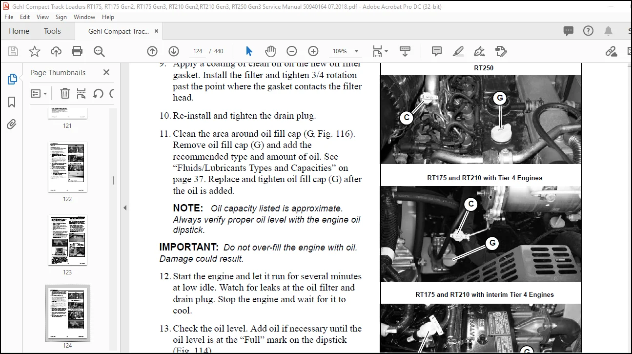
Changing Engine Oil and Filter…………………………………………………………………………………………………….123
Engine Air Filters…………………………………………………………………………………………………………………..125
Changing Air Filter Elements………………………………………………………………………………………………………….125
Engine Cooling System………………………………………………………………………………………………………………..126
Checking Coolant Level……………………………………………………………………………………………………………126
Cleaning Radiator Fins……………………………………………………………………………………………………………127
Draining/Refilling Cooling System………………………………………………………………………………………………….127
Belt Maintenance…………………………………………………………………………………………………………………….128
Checking and Adjusting Belt Tension………………………………………………………………………………………………..128
Air Conditioning Belt…………………………………………………………………………………………………………….129
DPF Service…………………………………………………………………………………………………………………………….129
Fuel System Maintenance………………………………………………………………………………………………………………….129
Adding Fuel…………………………………………………………………………………………………………………………130
Water Separator Inspection/Maintenance…………………………………………………………………………………………………130
Changing Fuel Filter…………………………………………………………………………………………………………………132
Hydraulic System Maintenance……………………………………………………………………………………………………………..133
Checking Hydraulic Oil Level………………………………………………………………………………………………………….133
Changing Hydraulic Oil and Filter……………………………………………………………………………………………………..134
Hydraulic Hose Maintenance……………………………………………………………………………………………………………….136
Travel Motor Maintenance…………………………………………………………………………………………………………………137
Travel Motor Gearbox Oil……………………………………………………………………………………………………………..137
Track Maintenance……………………………………………………………………………………………………………………….137
Track Replacement……………………………………………………………………………………………………………………138
General Lubrication……………………………………………………………………………………………………………………..141
Tilting ROPS/FOPS……………………………………………………………………………………………………………………….142
Raising ROPS/FOPS……………………………………………………………………………………………………………………142
Lower ROPS/FOPS……………………………………………………………………………………………………………………..144
Electrical System……………………………………………………………………………………………………………………….145
Battery…………………………………………………………………………………………………………………………….145
Using a Booster Battery (Jump-Starting)………………………………………………………………………………………………..146
Fuses and Relays…………………………………………………………………………………………………………………….147
Engine Compartment Fuses/Relays (Model RT250)……………………………………………………………………………………….147
Engine Compartment Fuses/Relays……………………………………………………………………………………………………149
Engine Compartment Fuses/Relays……………………………………………………………………………………………………151
Fuses Under ROPS/FOPS…………………………………………………………………………………………………………….152
Control Modules……………………………………………………………………………………………………………………..153
Multi-function Control Module……………………………………………………………………………………………………..153
Lift Arm and Standard Auxiliary Flow Control Module………………………………………………………………………………….153
Engine Control Module (ECU)……………………………………………………………………………………………………….153
Main/Drive Control Module…………………………………………………………………………………………………………153
Long-Term Storage……………………………………………………………………………………………………………………….154
Before Storage………………………………………………………………………………………………………………………154
After Storage……………………………………………………………………………………………………………………….154
Air Conditioning Maintenance……………………………………………………………………………………………………………..155
Air Conditioning Filters……………………………………………………………………………………………………………..155
Cab Air Filter…………………………………………………………………………………………………………………..155
Outside Air Intake Filter…………………………………………………………………………………………………………155
Windshield Washer Reservoir………………………………………………………………………………………………………………156
Final Shutdown / Decommissioning………………………………………………………………………………………………………….157
Before Disposal……………………………………………………………………………………………………………………..157
Machine Disposal…………………………………………………………………………………………………………………….157
Maintenance Log…………………………………………………………………………………………………………………………158
Lift Arm and ROPS/FOPS………………………………………………………………………………………………………………………161
Lift Arm Alignment Stops…………………………………………………………………………………………………………………161
Tilt Stop Adjustment…………………………………………………………………………………………………………………….161
Lift Arm Removal………………………………………………………………………………………………………………………..164
Lift Arm Installation……………………………………………………………………………………………………………………167
ROPS/FOPS Service……………………………………………………………………………………………………………………….169
ROPS/FOPS Removal……………………………………………………………………………………………………………………….169
ROPS/FOPS Installation…………………………………………………………………………………………………………………..175
Model RT250 Engine Removal/ Installation………………………………………………………………………………………………………183
Engine Removal – Model RT250……………………………………………………………………………………………………………..183
Engine Installation – Model RT250…………………………………………………………………………………………………………196
Models RT175/RT210 Tier 4 Engine Removal/Installation…………………………………………………………………………………………..209
Tier 4 Engine Removal Model RT175 (S/N 811001 and Up) Model RT210 (S/N 921001 and Up)…………………………………………………………..209
Tier 4 Engine Installation Model RT175 (S/N 811000 and Up) Model RT210 (S/N 921000 and Up)………………………………………………………222
RT175/RT210 interim Tier 4 Engine Removal/Installation………………………………………………………………………………………….235
Interim Tier 4 Engine Removal Model RT175 (S/N 811000 and Before) Model RT210 (S/N 921000 and Before)…………………………………………….235
Interim Tier 4 Engine Installation Model RT175 (S/N 811000 and Before) Model RT210 (S/N 921000 and Before)………………………………………..249
Hydraulic Equipment…………………………………………………………………………………………………………………………265
General Hydraulic Service Notes…………………………………………………………………………………………………………..265
Hydraulic Hoses/Piping……………………………………………………………………………………………………………….265
Seals………………………………………………………………………………………………………………………………265
Hydraulic Oil Analysis…………………………………………………………………………………………………………………..266
Hydraulic Control Valve………………………………………………………………………………………………………………….266
Main Control Valve Removal……………………………………………………………………………………………………………266
Main Control Valve Installation………………………………………………………………………………………………………. 0
Main Control Valve Removal……………………………………………………………………………………………………………267
Main Control Valve Installation……………………………………………………………………………………………………….267
High-Flow Hydraulics…………………………………………………………………………………………………………………268
Hydraulic Pilot Valve……………………………………………………………………………………………………………………268
Self-Level Valve………………………………………………………………………………………………………………………..269
Float/Hydraglide™ Valve………………………………………………………………………………………………………………….269
Travel Drive Motors……………………………………………………………………………………………………………………..270
Drive Motor Idle Speed……………………………………………………………………………………………………………….270
Drive Motor High Speed Adjustment……………………………………………………………………………………………………..270
Model RT175 (Serial Numbers 10721 and Up), Model RT210 (Serial Numbers 21041 and Up), Model 250 (All Serial Numbers)………………………..270
Model RT175 (Serial Numbers 10720 and before), Model RT210 (Serial Numbers 21040 and before)……………………………………………..270
Travel Motor Gearbox Oil……………………………………………………………………………………………………………..271
Hydrostatic Drive Pump…………………………………………………………………………………………………………………..271
Hydrostatic Pump Swash Plates…………………………………………………………………………………………………………….271
Swash Plate Sensors………………………………………………………………………………………………………………….271
Forward and Reverse Solenoids…………………………………………………………………………………………………………272
Hydrostatic Pump Removal…………………………………………………………………………………………………………………272
Hydrostatic Pump Installation…………………………………………………………………………………………………………….275
Hydrostatic Pump Drive Coupling Removal and Installation…………………………………………………………………………………….278
Installation………………………………………………………………………………………………………………………..279
Hydrostatic Pump Input Shaft Seal Replacement………………………………………………………………………………………………280
Input Shaft Seal Removal……………………………………………………………………………………………………………..280
Input Shaft Seal Installation…………………………………………………………………………………………………………281
Hydraulic Gear Pump……………………………………………………………………………………………………………………..282
Hydraulic Cylinder Disassembly/ Assembly…………………………………………………………………………………………………..282
Cylinder Disassembly…………………………………………………………………………………………………………………283
Cylinder Assembly……………………………………………………………………………………………………………………284
Bleeding Air After Cylinder Installation……………………………………………………………………………………………….285
Hydraulic System Tests………………………………………………………………………………………………………………………287
Hydrostatic Pumps……………………………………………………………………………………………………………………….287
Hydrostatic Pump (Later Machines)……………………………………………………………………………………………………..287
Hydrostatic Pump (Early Machines)……………………………………………………………………………………………………..288
Hydrostatic Drive System Pressures………………………………………………………………………………………………………..289
Hydrostatic Charge Pressure Test and Adjustment…………………………………………………………………………………………….289
Main Relief Pressure Test………………………………………………………………………………………………………………..290
Main Pressure Adjustment…………………………………………………………………………………………………………………291
Tilt/Lift Cylinder Relief Pressure Tests…………………………………………………………………………………………………..292
Inspection………………………………………………………………………………………………………………………….292
Cylinder Rod/Base End Pressure Tests…………………………………………………………………………………………………..293
Tilt Cylinder Base End Pressure Test……………………………………………………………………………………………….293
Tilt Cylinder Rod End Pressure Test………………………………………………………………………………………………..294
Lift Cylinder Base End Pressure Test……………………………………………………………………………………………….294
Lift Cylinder Rod End Pressure Test………………………………………………………………………………………………..295
Cylinder Drift Tests…………………………………………………………………………………………………………………….296
Tilt Cylinder Drift Test……………………………………………………………………………………………………………..296
Lift Cylinder Drift Test……………………………………………………………………………………………………………..296
Cylinder Internal Leakage Tests…………………………………………………………………………………………………………..296
Tilt Cylinder Internal Leakage Test……………………………………………………………………………………………………296
Lift Cylinder Internal Leakage Test……………………………………………………………………………………………………297
Lift/Tilt Relief Pressure Adjustment…………………………………………………………………………………………………..298
Electrical/Control Systems…………………………………………………………………………………………………………………..299
Electrical Schematics……………………………………………………………………………………………………………………299
Battery………………………………………………………………………………………………………………………………..299
Power Distribution………………………………………………………………………………………………………………………299
Power Distribution Module Fuse Socket Test……………………………………………………………………………………………..299
Main Power Relay…………………………………………………………………………………………………………………….300
Relay Testing……………………………………………………………………………………………………………………….300
Machine Test…………………………………………………………………………………………………………………….300
Bench Test………………………………………………………………………………………………………………………300
Electrical Control System………………………………………………………………………………………………………………..301
Electrical Control System General Information…………………………………………………………………………………………..301
CAN System General Information………………………………………………………………………………………………………..301
Control Module Locations……………………………………………………………………………………………………………..302
Multi-function Control/Interlock Module (Controller 3)……………………………………………………………………………….303
Engine Control Module (ECU)……………………………………………………………………………………………………….304
Main ECU Power Relay 2……………………………………………………………………………………………………………304
Lift Arm and Standard Auxiliary Flow Control Module (Maestro Controller 1)……………………………………………………………..305
Control Module (Maestro Controller 2)………………………………………………………………………………………………305
Optional High-Flow Module (Early Machines)………………………………………………………………………………………….305
Multi-Function Display……………………………………………………………………………………………………………306
CAN System Service/Computer Connection…………………………………………………………………………………………………….307
J1939 Data Connector…………………………………………………………………………………………………………………307
Electronics Diagnostic Kit……………………………………………………………………………………………………………307
CAN/Computer Connection Harnesses……………………………………………………………………………………………………..307
Service Adapter Harness…………………………………………………………………………………………………………..307
Deutz Engine CAN/Computer Connection Harness (SerDia) (Model RT250)……………………………………………………………………….308
Lighting……………………………………………………………………………………………………………………………….309
Work Light Bulb Replacement…………………………………………………………………………………………………………..309
Tail Light Bulb Replacement…………………………………………………………………………………………………………..310
Dome Light Bulb Replacement…………………………………………………………………………………………………………..311
Electronics Diagnostic Kit…………………………………………………………………………………………………………………..313
Diagnostic Kit Operation…………………………………………………………………………………………………………………313
Displayed Telemetry Information…………………………………………………………………………………………………………..314
Troubleshooting…………………………………………………………………………………………………………………………….315
Engine Troubleshooting…………………………………………………………………………………………………………………..315
Indicator Lamp Troubleshooting……………………………………………………………………………………………………………316
Seal and Hose Troubleshooting…………………………………………………………………………………………………………….317
Hydraulic System Troubleshooting………………………………………………………………………………………………………….318
Hydrostatic Travel Drive System Troubleshooting…………………………………………………………………………………………….320
Hydrostatic Drive Motors Troubleshooting…………………………………………………………………………………………………..322
Electrical Troubleshooting……………………………………………………………………………………………………………….323
Miscellaneous Troubleshooting…………………………………………………………………………………………………………….323
Error Codes…………………………………………………………………………………………………………………………….324
Controller Communication Error Codes…………………………………………………………………………………………………..324
Yanmar Engine Diagnostic Trouble Codes (DTC) – Models RT175/RT210…………………………………………………………………………324
Deutz Engine Error Codes – Model RT250…………………………………………………………………………………………………332
Drive and Valve Error Codes…………………………………………………………………………………………………………..337
Schematics…………………………………………………………………………………………………………………………………345
Schematic Conventions……………………………………………………………………………………………………………………345
Model RT250 (SN 70501 and Up) Schematics…………………………………………………………………………………………………..346
RT250 Fuse/Relay Locations Index………………………………………………………………………………………………………346
RT250 Connector / Splice Locations Index……………………………………………………………………………………………….347
Engine/Starting and Charging – Model RT250……………………………………………………………………………………………..350
Engine Sensors – Models RT250…………………………………………………………………………………………………………351
Engine ECU – Models RT250…………………………………………………………………………………………………………….352
Power Distribution/Fuses – Models RT250………………………………………………………………………………………………..353
Power Distribution/Relays – Models RT250……………………………………………………………………………………………….354
I/O Controller – Models RT250…………………………………………………………………………………………………………355
Solenoid Controller A – Models RT250…………………………………………………………………………………………………..356
Solenoid Controller B – Models RT250…………………………………………………………………………………………………..357
Operator/Drive Controls – Models RT250…………………………………………………………………………………………………358
High-Flow/Self-Level/Power-A-Tach® Quick Attach System – Models RT250……………………………………………………………………..359
HVAC – Models RT250………………………………………………………………………………………………………………….360
Track Tension/Work Lights – Models RT250……………………………………………………………………………………………….361
Wipers/Washer Pump – Models RT250……………………………………………………………………………………………………..362
EU Road Lighting – Models RT250……………………………………………………………………………………………………….363
Auxiliary Power/Dome Light/Radio – Models RT250…………………………………………………………………………………………364
Operator CAN Interface – Models RT250………………………………………………………………………………………………….365
Grounds – Models RT250……………………………………………………………………………………………………………….366
Model RT175 (Serial Numbers 811001 and Up) Model RT210 (Serial Numbers 921001 and Up)…………………………………………………………..367
RT175 (Serial Numbers 811001 and Up), RT210 (Serial Numbers 921001 and Up) Fuse/Relay Locations Index…………………………………………367
RT175 (Serial Numbers 811001 and Up), RT210 (Serial Numbers 921001 and Up) Connector / Splice Locations Index………………………………….368
Engine/Starting and Charging – Model RT175 (Serial Numbers 811001 and Up) Model RT210 (Serial Numbers 921001 and Up)……………………………370
Power Distribution/Fuses – Model RT175 (Serial Numbers 811001 and Up) Model RT210 (Serial Numbers 921001 and Up)……………………………….371
Power Distribution/Relays – Model RT175 (Serial Numbers 811001 and Up) Model RT210 (Serial Numbers 921001 and Up)………………………………372
Engine Sensors – Model RT175 (Serial Numbers 811001 and Up) Model RT210 (Serial Numbers 921001 and Up)………………………………………..373
Engine ECU – Model RT175 (Serial Numbers 811001 and Up) Model RT210 (Serial Numbers 921001 and Up)……………………………………………374
Engine ECU (Continued) – Model RT175 (Serial Numbers 811001 and Up) Model RT210 (Serial Numbers 921001 and Up)…………………………………375
I/O Controller – Model RT175 (Serial Numbers 811001 and Up) Model RT210 (Serial Numbers 921001 and Up)………………………………………..376
Solenoid Controller A – Model RT175 (Serial Numbers 811001 and Up) Model RT210 (Serial Numbers 921001 and Up)………………………………….377
Solenoid Controller B – Model RT175 (Serial Numbers 811001 and Up) Model RT210 (Serial Numbers 921001 and Up)………………………………….378
Operator/Drive Controls – Model RT175 (Serial Numbers 811001 and Up) Model RT210 (Serial Numbers 921001 and Up)………………………………..379
High-Flow/Self-Level/Power-A-Tach® Quick Attach System – Models RT175 (Serial Numbers 811001 and Up)/RT210 (Serial Numbers 921001 and Up)…………380
HVAC – Model RT175 (Serial Numbers 811001 and Up) Model RT210 (Serial Numbers 921001 and Up)…………………………………………………381
Track Tension/Work Lights – Model RT175 (Serial Numbers 811001 and Up) Model RT210 (Serial Numbers 921001 and Up)………………………………382
Wipers/Washer Pumps – Model RT175 (Serial Numbers 811001 and Up) Model RT210 (Serial Numbers 921001 and Up)……………………………………383
Auxiliary Power/Dome Light/Radio – Model RT175 (Serial Numbers 811001 and Up) Model RT210 (Serial Numbers 921001 and Up)………………………..384
Operator CAN Interface – Model RT175 (Serial Numbers 811001 and Up) Model RT210 (Serial Numbers 921001 and Up)…………………………………385
Grounds – Model RT175 (Serial Numbers 811001 and Up [Later Machines]) Model RT210 (Serial Numbers 921001 and Up [Later Machines])………………..386
Grounds – Model RT175 (Serial Numbers 811001 and Up [Early Machines]) Model RT210 (Serial Numbers 921001 and Up [Early Machines])………………..387
Model RT175 with Tier 4 Engines (Serial Numbers 411051 and Up) Model RT210 with Tier 4 Engines (Serial Numbers 921651 and Up)……………………….388
Models RT175 and RT210 with Tier 4 Engines – Fuse/Relay Locations Index……………………………………………………………………388
RT175 / RT210 with Tier 4 Engines Connector / Splice Locations Index………………………………………………………………………389
Engine/Starting and Charging – Models RT175 / RT210 with Tier 4 Engines……………………………………………………………………391
Power Distribution/Fuses – Models RT175 / RT210 with Tier 4 Engines……………………………………………………………………….392
Power Distribution/Relays – Models RT175 / RT210 with Tier 4 Engines………………………………………………………………………393
Engine Sensors – Models RT175 / RT210 with Tier 4 Engines………………………………………………………………………………..394
Engine ECU – Models RT175 / RT210 with Tier 4 Engines……………………………………………………………………………………395
Engine ECU (Continued) – Models RT175 / RT210 with Tier 4 Engines…………………………………………………………………………396
I/O Controller – Models RT175 / RT210 with Tier 4 Engines………………………………………………………………………………..397
Solenoid Controller A – Models RT175 / RT210 with Tier 4 Engines………………………………………………………………………….398
Solenoid Controller B – Models RT175 / RT210 with Tier 4 Engines………………………………………………………………………….399
Operator/Drive Controls – Models RT175 / RT210 with Tier 4 Engines………………………………………………………………………..400
High-Flow/Self-Level/Power-A-Tach® Quick Attach System – Models RT175/RT210 with Tier 4 Engines………………………………………………401
HVAC – Models RT175 / RT210 with Tier 4 Engines…………………………………………………………………………………………402
Track Tension/Work Lights – Models RT175 / RT210 with Tier 4 Engines………………………………………………………………………403
Wipers/Washer Pumps – Models RT175 / RT210 with Tier 4 Engines……………………………………………………………………………404
EU Road Lighting – Models RT175 / RT210 with Tier 4 Engines………………………………………………………………………………405
Auxiliary Power/Dome Light/Radio – Models RT175 / RT210 with Tier 4 Engines………………………………………………………………..406
Operator CAN Interface – Models RT175 / RT210 with Tier 4 Engines…………………………………………………………………………407
Grounds – Models RT175 / RT210 with Tier 4 Engines………………………………………………………………………………………408
Model RT175 with interim Tier 4 Engines (Serial Numbers 811000 and Before) Model RT210 with interim Tier 4 Engines (Serial Numbers 921000 and Before)….409
RT175 (Serial Numbers 811000 and Before), RT210 (Serial Numbers 921000 and Before) Fuse/Relay Locations Index………………………………….409
RT175 (Serial Numbers 811000 and Before), RT210 (Serial Numbers 921000 and Before) Connector / Splice Locations Index…………………………..410
Engine/Starting and Charging – Model RT175 / RT210 with interim Tier 4 Engines……………………………………………………………..413
Engine Sensors – Model RT175 / RT210 with interim Tier 4 Engines………………………………………………………………………….414
Engine ECU – Model RT175 / RT210 with interim Tier 4 Engines……………………………………………………………………………..415
Power Distribution – Model RT175 / RT210 with interim Tier 4 Engines………………………………………………………………………416
Controller 3 – Model RT175 / RT210 with interim Tier 4 Engines……………………………………………………………………………417
Controller 2 – Model RT175 / RT210 with interim Tier 4 Engines……………………………………………………………………………418
Controller 1 – Model RT175 / RT210 with interim Tier 4 Engines……………………………………………………………………………419
Operator/Drive Controls – Model RT175 / RT210 with interim Tier 4 Engines………………………………………………………………….420
High-Flow/Self-Level/Power-A-Tach® Quick Attach System – Model RT175 / RT210 with interim Tier 4 Engines………………………………………421
HVAC – Model RT175 / RT210 with interim Tier 4 Engines…………………………………………………………………………………..422
Track Tension/Lighting Control – Model RT175 / RT210 with interim Tier 4 Engines……………………………………………………………423
Wipers/Washer Pumps – Model RT175 / RT210 with interim Tier 4 Engines……………………………………………………………………..424
Work Lights – Model RT175 / RT210 with interim Tier 4 Engines…………………………………………………………………………….425
EU Road Lighting – Model RT175 / RT210 with interim Tier 4 Engines………………………………………………………………………..426
Operator Display/CAN Interface – Model RT175 / RT210 with interim Tier 4 Engines……………………………………………………………427
Grounds – Model RT175 / RT210 with interim Tier 4 Engines………………………………………………………………………………..428
Hydraulic Schematic…………………………………………………………………………………………………………………….. 0
Index……………………………………………………………………………………………………………………………………..431
A……………………………………………………………………………………………………………………………………..431
B……………………………………………………………………………………………………………………………………..431
C……………………………………………………………………………………………………………………………………..431
D……………………………………………………………………………………………………………………………………..431
E……………………………………………………………………………………………………………………………………..431
F……………………………………………………………………………………………………………………………………..432
G……………………………………………………………………………………………………………………………………..432
H……………………………………………………………………………………………………………………………………..432
J……………………………………………………………………………………………………………………………………..432
L……………………………………………………………………………………………………………………………………..432
M……………………………………………………………………………………………………………………………………..433
O……………………………………………………………………………………………………………………………………..433
P……………………………………………………………………………………………………………………………………..433
R……………………………………………………………………………………………………………………………………..433
S……………………………………………………………………………………………………………………………………..433
T……………………………………………………………………………………………………………………………………..434
U……………………………………………………………………………………………………………………………………..435
V……………………………………………………………………………………………………………………………………..435
W……………………………………………………………………………………………………………………………………..435
Torque Specifications……………………………………………………………………………………………………………………….437
SAE Torque Values……………………………………………………………………………………………………………………….439
Contact us: [email protected]
https://vimeo.com/801138818
PLEASE NOTE:
- This is the SAME MANUAL used by the dealerships to diagnose your vehicle
- No waiting for couriers / posts as this is a PDF manual and you can download it within 2 minutes time once you make the payment.
- Your payment is all safe and the delivery of the manual is INSTANT – You will be taken to the DOWNLOAD PAGE.
- So have no hesitations whatsoever and write to us about any queries you may have : heydownloadss @gmail.com
S.V