Gehl RT175 RT175 Gen:2 RT210 RT210 Gen:2 RT250 Compact Track Loader Operator’s Manual 50940360 – PDF DOWNLOAD
Original price was: $86.95.$28.95Current price is: $28.95.
Gehl RT175 RT175 Gen:2 RT210 RT210 Gen:2 RT250 Compact Track Loader Operator’s Manual 50940360 – PDF DOWNLOAD
RT175/RT175 Gen:2 Tier 4i Engines – Serial Numbers 10901 – 811000
Tier 4 Engines – Serial Numbers 811501 and Up
RT210/RT210 Gen:2 Tier 4i Engines – Serial Numbers 21201 – 921000
Tier 4 Engines – Serial Numbers 921501 and Up
RT250 Tier 4 Engines – Serial Numbers 70401 and Up
Description
Gehl RT175 RT175 Gen:2 RT210 RT210 Gen:2 RT250 Compact Track Loader Operator’s Manual 50940360 – PDF DOWNLOAD
FILE DETAILS:
Gehl RT175 RT175 Gen:2 RT210 RT210 Gen:2 RT250 Compact Track Loader Operator’s Manual 50940360 – PDF DOWNLOAD
Language : English
Pages : 266
Downloadable : Yes
File Type : PDF
Size: 11.4 MB
IMAGES PREVIEW OF THE MANUAL:
DESCRIPTION:
Gehl RT175 RT175 Gen:2 RT210 RT210 Gen:2 RT250 Compact Track Loader Operator’s Manual 50940360 – PDF DOWNLOAD
RT175/RT175 Gen:2 Tier 4i Engines – Serial Numbers 10901 – 811000
Tier 4 Engines – Serial Numbers 811501 and Up
RT210/RT210 Gen:2 Tier 4i Engines – Serial Numbers 21201 – 921000
Tier 4 Engines – Serial Numbers 921501 and Up
RT250 Tier 4 Engines – Serial Numbers 70401 and Up
This Operator’s Manual provides information about the safe and proper operation and maintenance for the machine. Major points of safe operation and maintenance are detailed in the Safety chapter of this manual. This manual also includes general troubleshooting and specification information about the machine. Follow the instructions in the Operator’s Manual Safety, Operation and Maintenance chapters, concerning accident prevention regulations, safety and occupational regulations, and machine and traffic regulations. Manitou Americas is not liable for damage resulting from the failure to follow these regulations.
- It is the owner’s or employer’s responsibility to fully instruct each operator in the proper and safe operation and maintenance of the machine. A storage container is provided behind the operator’s seat for storing the Operator’s Manual. After using the manual, return it to the storage container.
- This manual is considered a permanent part of the machine and should be with the machine at all times. If the machine is resold, include this operator’s manual as part of the sale. Replace this manual promptly if it becomes damaged, lost or stolen.
- Some illustrations in this manual may show doors, guards and shields open or removed for illustrative purposes only. BE SURE all doors, guards and shields are in their proper operating positions BEFORE starting the engine to operate the machine. Because of ongoing product improvements, information included in this manual may not exactly match the machine. Manitou Americas reserves the right to modify and improve products at any time without notice or obligation.
TABLE OF CONTENTS:
Gehl RT175 RT175 Gen:2 RT210 RT210 Gen:2 RT250 Compact Track Loader Operator’s Manual 50940360 – PDF DOWNLOAD
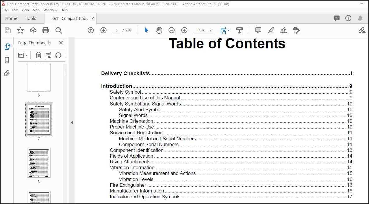
Delivery Checklists………………………………………………………………………………………………………………………i
Introduction………………………………………………………………………………………………………………………………..9
Safety Symbol ……………………………………………………………………………………………………………………………………… 9
Contents and Use of this Manual ……………………………………………………………………………………………………………. 9
Safety Symbol and Signal Words………………………………………………………………………………………………………….. 10
Safety Alert Symbol ………………………………………………………………………………………………………………………. 10
Signal Words ……………………………………………………………………………………………………………………………….. 10
Machine Orientation ……………………………………………………………………………………………………………………………. 10
Proper Machine Use……………………………………………………………………………………………………………………………. 10
Service and Registration ……………………………………………………………………………………………………………………… 11
Machine Model and Serial Numbers ……………………………………………………………………………………………….. 11
Component Serial Numbers …………………………………………………………………………………………………………… 11
Component Identification……………………………………………………………………………………………………………………… 13
Fields of Application ……………………………………………………………………………………………………………………………. 14
Using Attachments ……………………………………………………………………………………………………………………………… 14
Vibration Information …………………………………………………………………………………………………………………………… 15
Vibration Measurement and Actions………………………………………………………………………………………………… 15
Vibration Levels ……………………………………………………………………………………………………………………………. 16
Fire Extinguisher ………………………………………………………………………………………………………………………………… 16
Manufacturer Information …………………………………………………………………………………………………………………….. 16
Indicator and Operation Symbols………………………………………………………………………………………………………….. 17
Safety……………………………………………………………………………………………………………………………………….19
Safety Symbol and Signal Words………………………………………………………………………………………………………….. 19
Safety Alert Symbol ………………………………………………………………………………………………………………………. 19
Signal Words ……………………………………………………………………………………………………………………………….. 19
Mandatory Safety Shutdown Procedure…………………………………………………………………………………………………. 20
Before Starting …………………………………………………………………………………………………………………………………… 20
During Operation ………………………………………………………………………………………………………………………………… 21
Applications with Load-Handling Devices ………………………………………………………………………………………………. 24
Parking the Machine……………………………………………………………………………………………………………………………. 25
Electrical Energy ………………………………………………………………………………………………………………………………… 25
Maintenance and Service Safety Practices…………………………………………………………………………………………….. 25
Battery Hazards………………………………………………………………………………………………………………………………….. 27
Fire Hazards………………………………………………………………………………………………………………………………………. 28
Additional Safety Equipment ………………………………………………………………………………………………………………… 28
Crystalline Silica Exposure…………………………………………………………………………………………………………………… 29
Transporting the Machine…………………………………………………………………………………………………………………….. 29
Lifting the Machine with a Crane …………………………………………………………………………………………………………… 29
Loading and Transporting the Machine………………………………………………………………………………………………….. 29
Safety Decals …………………………………………………………………………………………………………………………………….. 30
New Decal Application…………………………………………………………………………………………………………………… 30
ANSI-Style Safety Decals…………………………………………………………………………………………………………………….. 31
ISO-Style Safety Decals………………………………………………………………………………………………………………………. 33
Specifications …………………………………………………………………………………………………………………………..35
Fluids/Lubricants Types and Capacities…………………………………………………………………………………………………. 35
Dimensions………………………………………………………………………………………………………………………………………… 36
Payloads/Capacities……………………………………………………………………………………………………………………………. 38
Weights …………………………………………………………………………………………………………………………………………….. 39
Track Drive ………………………………………………………………………………………………………………………………………… 39
Coolant Compound Table ……………………………………………………………………………………………………………………. 39
Table of Contents
50940360/AP1015 2 Printed in U.S.A.
Engine………………………………………………………………………………………………………………………………………………..40
Hydraulic System…………………………………………………………………………………………………………………………………41
General ………………………………………………………………………………………………………………………………………..41
Drive Hydraulics…………………………………………………………………………………………………………………………….42
Pumps………………………………………………………………………………………………………………………………………….42
Cylinders ………………………………………………………………………………………………………………………………………43
Forces and Cycle Times …………………………………………………………………………………………………………………43
Electrical System …………………………………………………………………………………………………………………………………44
Sound Power/Pressure Levels ………………………………………………………………………………………………………………44
Vibration Levels …………………………………………………………………………………………………………………………………..44
Features……………………………………………………………………………………………………………………………………………..45
Standard Features ……………………………………………………………………………………………………………………………….45
Optional Features ………………………………………………………………………………………………………………………………..45
Common Materials and Densities…………………………………………………………………………………………………………..46
Controls……………………………………………………………………………………………………………………………………47
Multi-Function Display ………………………………………………………………………………………………………………………….48
Switches/Indicators………………………………………………………………………………………………………………………………49
Multi-Function Display Screens ……………………………………………………………………………………………………………..50
Screen Access ………………………………………………………………………………………………………………………………50
Status, Maintenance and Error Code Screens …………………………………………………………………………………..50
Configuration Screens ……………………………………………………………………………………………………………………52
Audible Alerts………………………………………………………………………………………………………………………………..55
Control Joysticks………………………………………………………………………………………………………………………………….55
Joystick Tilt Function ISO/D-H Control Patterns……………………………………………………………………………55
Activating D-H Control Pattern Option …………………………………………………………………………………………55
Deactivating D-H Control Pattern Option……………………………………………………………………………………..56
Left Joystick Functions……………………………………………………………………………………………………………………56
Right Joystick Functions …………………………………………………………………………………………………………………57
Joystick Buttons/Switch Functions……………………………………………………………………………………………………57
Joystick Control Sensitivity ……………………………………………………………………………………………………………..58
Configuring Control Sensitivity……………………………………………………………………………………………………58
Straight Tracking Adjust………………………………………………………………………………………………………………………..59
Parking Brake/Work Hydraulics Lock-out ………………………………………………………………………………………………..60
Cab Heat and Air Conditioning (Option) ………………………………………………………………………………………………….61
Operator’s Seat……………………………………………………………………………………………………………………………………61
Seat Forward and Back Horizontal Adjustment ………………………………………………………………………………….62
Seat Height Vertical Height/Weight Suspension Adjustment………………………………………………………………..62
Air Suspension ………………………………………………………………………………………………………………………..62
Mechanical Suspension…………………………………………………………………………………………………………….62
Seat Belt …………………………………………………………………………………………………………………………………………….62
Fastening/Unfastening the Seat Belt ………………………………………………………………………………………………..62
Armrest/Joystick Console Adjustment …………………………………………………………………………………………………….63
Throttle Controls ………………………………………………………………………………………………………………………………….63
Travel Controls ……………………………………………………………………………………………………………………………………64
Travel Speed Range Selection ………………………………………………………………………………………………………………64
Activating Travel Speed Limit Option…………………………………………………………………………………………..64
Deactivating Travel Speed Limit Option ………………………………………………………………………………………65
Travel Speed Limit Option Operation ………………………………………………………………………………………….66
Lift Arm Float Button …………………………………………………………………………………………………………………………….66
Hydraglide™ Button (Option)…………………………………………………………………………………………………………………67
Work Lights…………………………………………………………………………………………………………………………………………67
Work Lights …………………………………………………………………………………………………………………………………..67
Battery Disconnect Switch (Option) ………………………………………………………………………………………………………..68
Windshield Wipers/Washer……………………………………………………………………………………………………………………68
Wiper/Washer Control…………………………………………………………………………………………………………………….68
Washer Fluid Reservoir ………………………………………………………………………………………………………………….68
Printed in U.S.A. 3 50940360/AP1015
Operation………………………………………………………………………………………………………………………………….69
Operational Checks…………………………………………………………………………………………………………………………….. 69
Pre-Start Checks ………………………………………………………………………………………………………………………….. 69
Checks During Operation ………………………………………………………………………………………………………………. 70
Parking Checks ……………………………………………………………………………………………………………………………. 70
Before Operation ………………………………………………………………………………………………………………………………… 71
Cab Entry and Exit………………………………………………………………………………………………………………………… 71
Opening/Closing the Cab Door (Option)…………………………………………………………………………………………… 71
Cab Door Emergency Exit ……………………………………………………………………………………………………………… 72
Cab Door Removal……………………………………………………………………………………………………………………….. 72
Seat and Armrest/Joystick Console Adjustment………………………………………………………………………………… 72
Seat Belt ……………………………………………………………………………………………………………………………………… 73
Parking Brake ………………………………………………………………………………………………………………………………. 73
Disengage Parking Brake ………………………………………………………………………………………………………… 74
Starting the Engine……………………………………………………………………………………………………………………………… 74
Cold-Starting………………………………………………………………………………………………………………………………… 75
After Starting………………………………………………………………………………………………………………………………… 75
Warm Up …………………………………………………………………………………………………………………………………………… 76
Run-In Period …………………………………………………………………………………………………………………………………….. 76
Stopping the Engine ……………………………………………………………………………………………………………………………. 76
Engine Stalling …………………………………………………………………………………………………………………………………… 77
Diesel Particulate Filter (DPF) Regeneration Procedures…………………………………………………………………………. 77
Reset Regeneration………………………………………………………………………………………………………………………. 78
Stationary Regeneration………………………………………………………………………………………………………………… 78
Forcing Stationary Regeneration ………………………………………………………………………………………………. 80
Regeneration Inhibit ……………………………………………………………………………………………………………………… 81
Cancelling Regeneration Inhibit ………………………………………………………………………………………………… 82
Recovery Regeneration…………………………………………………………………………………………………………………. 83
DPF Service ………………………………………………………………………………………………………………………………… 84
After Operation …………………………………………………………………………………………………………………………………… 85
Jump-Starting …………………………………………………………………………………………………………………………………….. 85
Travel Drive Operation ………………………………………………………………………………………………………………………… 87
ISO Pattern Travel Drive Controls……………………………………………………………………………………………… 88
D-H Pattern Travel Drive Controls (Option) ………………………………………………………………………………… 88
Straight Tracking Adjust ………………………………………………………………………………………………………………… 89
Rubber Track Use Cautions and Tips ……………………………………………………………………………………………………. 90
Sprocket Tooth Wear and Track Life……………………………………………………………………………………………….. 92
Travel Drive Error Condition Operation (Limp Mode) …………………………………………………………………………. 93
Alternate Transport Mode Activation………………………………………………………………………………………….. 93
Alternate Transport Mode Cancel ……………………………………………………………………………………………… 94
Backup Alarm ………………………………………………………………………………………………………………………………. 94
Lift Arm Operation ………………………………………………………………………………………………………………………………. 95
Attachment Transport Position ……………………………………………………………………………………………………….. 95
Joystick Control Patterns……………………………………………………………………………………………………………….. 95
ISO Pattern Lift Arm Operation Controls…………………………………………………………………………………….. 95
D-H Pattern Lift Arm Operation Controls (Option)………………………………………………………………………… 96
Self-Leveling………………………………………………………………………………………………………………………………………. 97
Self-Leveling Cancel (Option)…………………………………………………………………………………………………………. 97
Lift Arm Float ……………………………………………………………………………………………………………………………………… 98
Hydraglide™ Ride Control System (Option)……………………………………………………………………………………………. 99
Hydraulics Control Lock …………………………………………………………………………………………………………………….. 100
Lift Arm Support ……………………………………………………………………………………………………………………………….. 101
Engage Lift Arm Support ……………………………………………………………………………………………………………… 101
Disengage Lift Arm Support …………………………………………………………………………………………………………. 102
Connecting/Disconnecting Attachments……………………………………………………………………………………………….. 103
Connecting Attachments ……………………………………………………………………………………………………………… 103
Disconnecting Attachments ………………………………………………………………………………………………………….. 104
50940360/AP1015 4 Printed in U.S.A.
Powering Attachments with Hydraulic Function………………………………………………………………………………………105
Connecting Hydraulic Attachments to the Auxiliary Hydraulic Circuits …………………………………………………105
Disconnecting Hydraulic Attachments from the Auxiliary Hydraulics Circuit………………………………………….105
Auxiliary Hydraulics Operation……………………………………………………………………………………………………….106
Standard-Flow Auxiliary Hydraulics Control ……………………………………………………………………………….106
High-Flow Auxiliary Hydraulics Control (Option) …………………………………………………………………………106
Optional 14-Pin Connector ………………………………………………………………………………………………………………….107
Switch / Pin Assignments………………………………………………………………………………………………………………107
Working with Buckets …………………………………………………………………………………………………………………………108
Digging Tips ………………………………………………………………………………………………………………………………..108
Safety Instructions When Working with Buckets……………………………………………………………………………….108
Working with Standard Buckets ……………………………………………………………………………………………………..109
Scooping……………………………………………………………………………………………………………………………….109
Loading…………………………………………………………………………………………………………………………………109
Tips When Loading Trucks ………………………………………………………………………………………………………110
Digging …………………………………………………………………………………………………………………………………110
Grading without Float………………………………………………………………………………………………………………110
Grading Using Float………………………………………………………………………………………………………………..111
Backfilling ……………………………………………………………………………………………………………………………..112
Working with Pallet Forks ……………………………………………………………………………………………………………………112
Safety Instructions When Working with Pallet Forks …………………………………………………………………………112
Transporting Loads Using Pallet Forks……………………………………………………………………………………………114
Loading Pallet Forks……………………………………………………………………………………………………………….114
Lifting Loads Using Pallet Forks ……………………………………………………………………………………………….114
Transporting Load Using Pallet Forks ……………………………………………………………………………………….114
Setting Down Loads Using Pallet Forks …………………………………………………………………………………….114
Lifting the Machine using a Crane ………………………………………………………………………………………………………..115
Crane Lifting Preparation ………………………………………………………………………………………………………………115
Loading and Transporting the Machine on a Transport Vehicle ………………………………………………………………..116
Loading and Securing the Machine ………………………………………………………………………………………………..116
Storage Box ………………………………………………………………………………………………………………………………………117
Maintenance……………………………………………………………………………………………………………………………119
Maintenance Schedule ……………………………………………………………………………………………………………………….120
Checks, Cleaning and Inspection …………………………………………………………………………………………………..120
Leakage Check ……………………………………………………………………………………………………………………………121
Lubrication and Filter Changes ………………………………………………………………………………………………………121
Functional Check …………………………………………………………………………………………………………………………121
Maintenance Interval ………………………………………………………………………………………………………………………….122
Engine Maintenance …………………………………………………………………………………………………………………………..123
Engine Access …………………………………………………………………………………………………………………………….123
Closing Engine Covers ……………………………………………………………………………………………………………123
Engine Oil …………………………………………………………………………………………………………………………………..124
Checking Engine Oil Level ………………………………………………………………………………………………………124
Changing Engine Oil and Filter…………………………………………………………………………………………………125
Engine Air Filters………………………………………………………………………………………………………………………….127
Changing Air Filter Elements …………………………………………………………………………………………………………127
Engine Cooling System…………………………………………………………………………………………………………………128
Checking Coolant Level…………………………………………………………………………………………………………..128
Cleaning Radiator Fins ……………………………………………………………………………………………………………129
Draining/Refilling Cooling System …………………………………………………………………………………………….129
V-Belt Maintenance………………………………………………………………………………………………………………………130
Checking and Adjusting V-belt Tension……………………………………………………………………………………..130
Air Conditioning V-Belt ……………………………………………………………………………………………………………131
DPF Service………………………………………………………………………………………………………………………………………131
Printed in U.S.A. 5 50940360/AP1015
Fuel System Maintenance………………………………………………………………………………………………………………….. 131
Adding Fuel ……………………………………………………………………………………………………………………………….. 132
Water Separator Inspection/Maintenance ………………………………………………………………………………………. 132
Changing Fuel Filter ……………………………………………………………………………………………………………………. 134
Hydraulic System Maintenance…………………………………………………………………………………………………………… 135
Checking Hydraulic Oil Level………………………………………………………………………………………………………… 135
Changing Hydraulic Oil and Filter………………………………………………………………………………………………….. 136
Hydraulic Hose Maintenance ……………………………………………………………………………………………………………… 138
Travel Motor Maintenance………………………………………………………………………………………………………………….. 139
Travel Motor Gearbox Oil …………………………………………………………………………………………………………….. 139
Track Maintenance……………………………………………………………………………………………………………………………. 139
Track Replacement …………………………………………………………………………………………………………………….. 140
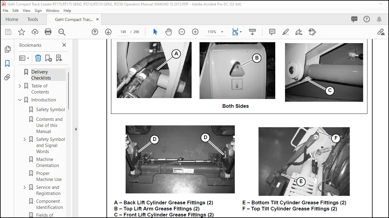
General Lubrication …………………………………………………………………………………………………………………………… 143
Tilting ROPS/FOPS…………………………………………………………………………………………………………………………… 144
Raising ROPS/FOPS…………………………………………………………………………………………………………………… 144
Lower ROPS/FOPS…………………………………………………………………………………………………………………….. 145
Electrical System………………………………………………………………………………………………………………………………. 146
Battery ………………………………………………………………………………………………………………………………………. 146
Using a Booster Battery (Jump-Starting)………………………………………………………………………………………… 147
Fuses and Relays……………………………………………………………………………………………………………………….. 148
Engine Compartment Fuses/Relays
Model RT250 (SN 70401 and Up) ………………………………………………………………………………………… 148
Engine Compartment Fuses/Relays ………………………………………………………………………………………… 150
Engine Compartment Fuses/Relays ………………………………………………………………………………………… 152
Fuses Under ROPS/FOPS……………………………………………………………………………………………………… 153
Control Modules …………………………………………………………………………………………………………………………. 154
Multi-function Control Module …………………………………………………………………………………………………. 154
Lift Arm and Standard Auxiliary Flow Control Module…………………………………………………………………. 154
Engine Control Module (ECU)…………………………………………………………………………………………………. 154
Main/Drive Control Module……………………………………………………………………………………………………… 154
Long-Term Storage …………………………………………………………………………………………………………………………… 155
Before Storage …………………………………………………………………………………………………………………………… 155
After Storage ……………………………………………………………………………………………………………………………… 155
Air Conditioning Maintenance …………………………………………………………………………………………………………….. 156
Air Conditioning Filters ………………………………………………………………………………………………………………… 156
Cab Air Filter ………………………………………………………………………………………………………………………… 156
Outside Air Intake Filter………………………………………………………………………………………………………….. 156
Windshield Washer Reservoir …………………………………………………………………………………………………………….. 157
Final Shutdown / Decommissioning …………………………………………………………………………………………………….. 158
Before Disposal ………………………………………………………………………………………………………………………….. 158
Machine Disposal ……………………………………………………………………………………………………………………….. 158
Maintenance Log………………………………………………………………………………………………………………………………. 159
Troubleshooting ……………………………………………………………………………………………………………………..161
Engine Troubleshooting …………………………………………………………………………………………………………………….. 161
Indicator Lamp Troubleshooting………………………………………………………………………………………………………….. 162
Seal and Hose Troubleshooting ………………………………………………………………………………………………………….. 163
Hydraulic System Troubleshooting………………………………………………………………………………………………………. 164
Hydrostatic Travel Drive System Troubleshooting …………………………………………………………………………………. 165
Electrical Troubleshooting ………………………………………………………………………………………………………………….. 167
Miscellaneous Troubleshooting…………………………………………………………………………………………………………… 168
Error Codes……………………………………………………………………………………………………………………………………… 168
Controller Communication Error Codes………………………………………………………………………………………….. 168
Engine Error Codes …………………………………………………………………………………………………………………….. 168
Drive and Valve Error Codes………………………………………………………………………………………………………… 176
50940360/AP1015 6 Printed in U.S.A.
Schematics …………………………………………………………………………………………………………………………….185
Schematic Conventions ………………………………………………………………………………………………………………………185
Model RT250 (SN 70401 and Up) Schematics……………………………………………………………………………………….186
RT250 Fuse/Relay Locations Index………………………………………………………………………………………………..186
RT250 Connector / Splice Locations Index………………………………………………………………………………………187
Engine/Starting and Charging – Model RT250 …………………………………………………………………………………190
Engine Sensors – Models RT250 …………………………………………………………………………………………………..191
Engine ECU – Models RT250………………………………………………………………………………………………………..192
Power Distribution/Fuses – Models RT250………………………………………………………………………………………193
Power Distribution/Relays – Models RT250 …………………………………………………………………………………….194
I/O Controller – Models RT250 ………………………………………………………………………………………………………195
Solenoid Controller A – Models RT250……………………………………………………………………………………………196
Solenoid Controller B – Models RT250……………………………………………………………………………………………197
Operator/Drive Controls – Models RT250………………………………………………………………………………………..198
High-Flow/Self-Level/Power-A-Tach® Quick Attach System – Models RT250 …………………………………….199
HVAC – Models RT250…………………………………………………………………………………………………………………200
Track Tension/Work Lights – Models RT250……………………………………………………………………………………201
Wipers/Washer Pump – Models RT250…………………………………………………………………………………………..202
EU Road Lighting – Models RT250 ………………………………………………………………………………………………..203
Auxiliary Power/Dome Light/Radio – Models RT250 …………………………………………………………………………204
Operator CAN Interface – Models RT250………………………………………………………………………………………..205
Grounds – Models RT250……………………………………………………………………………………………………………..206
Model RT175 with Tier 4 Engines (Serial Numbers 811501 and Up)
Model RT210 with Tier 4 Engines (Serial Numbers 921501 and Up)………………………………………………………207
Models RT175 and RT210 with Tier 4 Engines – Fuse/Relay Locations Index ……………………………………..207
RT175 / RT210 with Tier 4 Engines Connector / Splice Locations Index ……………………………………………..208
Engine/Starting and Charging – Models RT175 / RT210 with Tier 4 Engines ……………………………………….210
Power Distribution/Fuses – Models RT175 / RT210 with Tier 4 Engines ……………………………………………..211
Power Distribution/Relays – Models RT175 / RT210 with Tier 4 Engines …………………………………………….212
Engine Sensors – Models RT175 / RT210 with Tier 4 Engines…………………………………………………………..213
Engine ECU – Models RT175 / RT210 with Tier 4 Engines ……………………………………………………………….214
Engine ECU (Continued) – Models RT175 / RT210 with Tier 4 Engines ……………………………………………..215
I/O Controller – Models RT175 / RT210 with Tier 4 Engines………………………………………………………………216
Solenoid Controller A – Models RT175 / RT210 with Tier 4 Engines ………………………………………………….217
Solenoid Controller B – Models RT175 / RT210 with Tier 4 Engines …………………………………………………..218
Operator/Drive Controls – Models RT175 / RT210 with Tier 4 Engines ……………………………………………….219
High-Flow/Self-Level/Power-A-Tach® Quick Attach System – Models RT175 / RT210 with Tier 4
Engines …………………………………………………………………………………………………………………………………….220
HVAC – Models RT175 / RT210 with Tier 4 Engines ………………………………………………………………………..221
Track Tension/Work Lights – Models RT175 / RT210 with Tier 4 Engines……………………………………………222
Wipers/Washer Pumps – Models RT175 / RT210 with Tier 4 Engines…………………………………………………223
EU Road Lighting – Models RT175 / RT210 with Tier 4 Engines ………………………………………………………..224
Auxiliary Power/Dome Light/Radio – Models RT175 / RT210 with Tier 4 Engines…………………………………225
Operator CAN Interface – Models RT175 / RT210 with Tier 4 Engines ……………………………………………….226
Grounds – Models RT175 / RT210 with Tier 4 Engines …………………………………………………………………….227
Model RT175 with interim Tier 4 Engines (Serial Numbers 10901 – 811000), Model RT210 with interim Tier 4 Engines
(Serial Numbers 21201 – 921000)……………………………………………………………………………………………..228
RT175 (Serial Numbers 10901 – 811000), RT210 (Serial Numbers 21201 – 921000) Fuse/Relay Locations Index………………………………………………………………………………………………………….
……………………………….228
RT175 (Serial Numbers 10901 – 811000), RT210 (Serial Numbers 21201 – 921000) Connector / Splice Locations
Index………………………………………………………………………………………………………………………………..229
Engine/Starting and Charging – Model RT175 / RT210 with interim Tier 4 Engines ………………………………232
Engine Sensors – Model RT175 / RT210 with interim Tier 4 Engines ………………………………………………….233
Engine ECU – Model RT175 / RT210 with interim Tier 4 Engines ………………………………………………………234
Power Distribution – Model RT175 / RT210 with interim Tier 4 Engines ………………………………………………235
Controller 3 – Model RT175 / RT210 with interim Tier 4 Engines………………………………………………………..236
Controller 2 – Model RT175 / RT210 with interim Tier 4 Engines………………………………………………………..237
Printed in U.S.A. 7 50940360/AP1015
Controller 1 – Model RT175 / RT210 with interim Tier 4 Engines ………………………………………………………. 238
Operator/Drive Controls – Model RT175 / RT210 with interim Tier 4 Engines……………………………………… 239
High-Flow/Self-Level/Power-A-Tach® Quick Attach System – Model RT175 / RT210 with interim Tier 4
Engines……………………………………………………………………………………………………………………………………. 240
HVAC – Model RT175 / RT210 with interim Tier 4 Engines………………………………………………………………. 241
Track Tension/Lighting Control – Model RT175 / RT210 with interim Tier 4 Engines……………………………. 242
Wipers/Washer Pumps – Model RT175 / RT210 with interim Tier 4 Engines ………………………………………. 243
Work Lights – Model RT175 / RT210 with interim Tier 4 Engines………………………………………………………. 244
EU Road Lighting – Model RT175 / RT210 with interim Tier 4 Engines………………………………………………. 245
Operator Display/CAN Interface – Model RT175 / RT210 with interim Tier 4 Engines ………………………….. 246
Grounds – Model RT175 / RT210 with interim Tier 4 Engines …………………………………………………………… 247
Hydraulic Schematic………………………………………………………………………………………………………………………….. 249
Index ………………………………………………………………………………………………………………………………………251
EC Declaration of Conformity ………………………………………………………………………………………………….255
Torque Specifications……………………………………………………………………………………………………………..257
Contact us: [email protected]
PLEASE NOTE:
- This is the SAME manual used by the dealers to troubleshoot any faults in your vehicle. This can be yours in 2 minutes after the payment is made.
- Contact us at [email protected] should you have any queries before your purchase or that you need any other service / repair / parts operators manual.
S.V