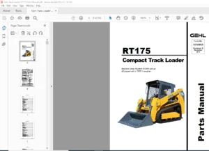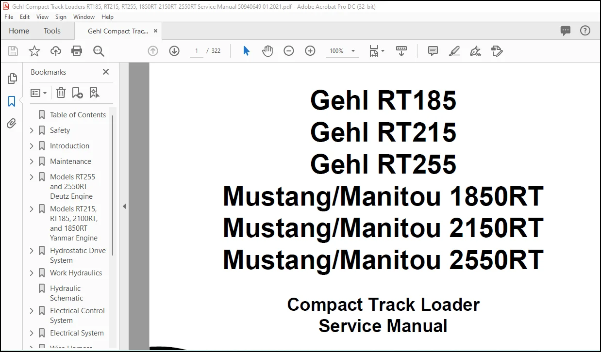
Gehl RT185, RT215, RT255 Mustang & Manitou 1850RT 2150RT 2550RT Compact Track Loader Service Manual 50940649 – PDF DOWNLOAD
Original price was: $86.95.$28.95Current price is: $28.95.
Gehl RT185, RT215, RT255 Mustang & Manitou 1850RT 2150RT 2550RT Compact Track Loader Service Manual 50940649 – PDF DOWNLOAD
Description
Gehl RT185, RT215, RT255 Mustang & Manitou 1850RT 2150RT 2550RT Compact Track Loader Service Manual 50940649 – PDF DOWNLOAD
FILE DETAILS:
Gehl RT185, RT215, RT255 Mustang & Manitou 1850RT 2150RT 2550RT Compact Track Loader Service Manual 50940649 – PDF DOWNLOAD
Language : English
Pages : 322
Downloadable : Yes
File Type : PDF
Size: 45.5 MB
IMAGES PREVIEW OF THE MANUAL:
DESCRIPTION:
Gehl RT185, RT215, RT255 Mustang & Manitou 1850RT 2150RT 2550RT Compact Track Loader Service Manual 50940649 – PDF DOWNLOAD
Introduction:
Contents and Use of this Manual:
This Service Manual provides information about the safe and proper service for the machine. Major points of safe service and operation are detailed in the Safety chapter of this manual. Some illustrations in this manual may show doors, guards and shields open or removed for illustrative purposes only.
- BE SURE all doors, guards and shields are in their proper operating positions BEFORE starting the engine to operate the machine. Because of ongoing product improvements, information included in this manual may not exactly match the machine. Manitou reserves the right to modify and improve products at any time without notice or obligation.
- The machine is provided from the factory with an Operator’s Manual. A storage container is provided behind the operator’s seat for storing the Operator’s Manual. After using the manual, return it to the storage container. The Operator’s Manual is considered a permanent part of the machine and should be with the machine at all times.
- Replace the Operator’s Manual promptly if it becomes damaged, lost or stolen. Follow the instructions in the Operator’s Manual Safety, Operation and Maintenance chapters concerning accident prevention regulations, safety and occupational regulations, and machine and traffic regulations. Manitou is not liable for damage resulting from the failure to follow these regulations.
TABLE OF CONTENTS:
Gehl RT185, RT215, RT255 Mustang & Manitou 1850RT 2150RT 2550RT Compact Track Loader Service Manual 50940649 – PDF DOWNLOAD
Table of Contents………………………………………………………………….. 3
Safety……………………………………………………………………………. 9
Safety Symbol and Signal Words…………………………………………………… 9
Safety Alert Symbol…………………………………………………………. 9
Signal Words……………………………………………………………….. 9
Mandatory Safety Shutdown Procedure………………………………………………. 10
Before Starting………………………………………………………………… 10
During Operation……………………………………………………………….. 11
Applications with Load-Handling Devices…………………………………………… 14
Parking the Machine…………………………………………………………….. 15
Electrical Energy………………………………………………………………. 15
Maintenance and Service Safety Practices………………………………………….. 15
Battery Hazards………………………………………………………………… 17
Fire Hazards…………………………………………………………………… 18
Additional Safety Equipment……………………………………………………… 19
Crystalline Silica Exposure……………………………………………………… 19
Transporting the Machine………………………………………………………… 19
Lifting the Machine with a Crane…………………………………………………. 19
Loading and Transporting the Machine……………………………………………… 20
Safety Decals………………………………………………………………….. 20
New Decal Application……………………………………………………….. 21
ANSI-Style Safety Decals………………………………………………………… 22
ISO-Style Safety Decals…………………………………………………………. 24
Lifting the Machine using a Crane………………………………………………… 26
Crane Lifting Preparation……………………………………………………. 26
Loading and Transporting the Machine on a Transport Vehicle…………………………. 27
Loading and Securing the Machine……………………………………………… 27
Introduction………………………………………………………………………. 29
Contents and Use of this Manual………………………………………………….. 29
Machine Orientation…………………………………………………………….. 29
Component Identification………………………………………………………… 30
Machine Model and Serial Number Locations…………………………………………. 31
Component Serial Numbers…………………………………………………….. 31
ROPS/FOPS Certification Label……………………………………………………. 32
Indicator and Operation Symbols………………………………………………….. 33
Machine Controls and Operation…………………………………………………… 34
Maintenance……………………………………………………………………….. 35
Maintenance Schedule……………………………………………………………. 36
Checks, Cleaning and Inspection………………………………………………. 36
Leakage Check………………………………………………………………. 37
Lubrication and Filter Changes……………………………………………….. 38
Functional Check……………………………………………………………. 38
Engine Maintenance……………………………………………………………… 40
Engine Access………………………………………………………………. 40
Closing Engine Covers……………………………………………………. 40
Engine Oil…………………………………………………………………. 41
Checking Engine Oil Level………………………………………………… 41
Changing Engine Oil and Filter……………………………………………. 42
Engine Air Filters………………………………………………………….. 44
Changing Air Filter Elements…………………………………………………. 44
Engine Cooling System……………………………………………………….. 45
Checking Coolant Level…………………………………………………… 45
Cleaning Radiator Fins…………………………………………………… 45
Draining/Refilling Cooling System…………………………………………. 46
Belt Maintenance……………………………………………………………. 47
Checking and Adjusting Belt Tension……………………………………….. 47
Air Conditioning Belt……………………………………………………. 47
DPF Service……………………………………………………………………. 48
Models RT185, RT215, 1850RT, and 2150RT with Tier 4 Engines……………………… 48
Fuel System Maintenance…………………………………………………………. 48
Adding Fuel………………………………………………………………… 48
Water Separator Inspection/Maintenance………………………………………… 49
Changing Fuel Filter………………………………………………………… 50
Hydraulic System Maintenance…………………………………………………….. 52
Checking Hydraulic Oil Level…………………………………………………. 52
Changing Hydraulic Oil and Filter…………………………………………….. 53
Hydraulic Hose Maintenance………………………………………………………. 55
Travel Motor Maintenance………………………………………………………… 56
Travel Motor Gearbox Oil…………………………………………………….. 56
Track Maintenance………………………………………………………………. 56
Track Replacement…………………………………………………………… 56
General Lubrication…………………………………………………………….. 57
Tilting ROPS/FOPS………………………………………………………………. 58
Raising ROPS/FOPS…………………………………………………………… 58
Lowering ROPS/FOPS………………………………………………………….. 59
Electrical System………………………………………………………………. 59
Battery……………………………………………………………………. 59
Using a Booster Battery (Jump-Starting)……………………………………….. 60
Fuses and Relays……………………………………………………………. 61
Fuse/Relay Box………………………………………………………….. 61
Main Fuses/Relays……………………………………………………….. 61
Power-A-Tach Relay………………………………………………………. 62
Optional 14-Pin Connector Fuses/Relays…………………………………….. 62
Lighting………………………………………………………………………. 63
Work Light Bulb Replacement………………………………………………….. 63
Tail Light Bulb Replacement………………………………………………….. 64
Dome Light Bulb Replacement………………………………………………….. 64
Long-Term Storage………………………………………………………………. 65
Before Storage……………………………………………………………… 65
After Storage………………………………………………………………. 65
Air Conditioning Maintenance…………………………………………………….. 66
Air Conditioning Filters…………………………………………………….. 66
Cab Air Filter………………………………………………………….. 66
Outside Air Intake Filter………………………………………………… 66
Windshield Washer Reservoir……………………………………………………… 67
Window Removal…………………………………………………………………. 67
Front Window Removal………………………………………………………… 67
Rear Window Removal…………………………………………………………. 67
Bottom Window Removal……………………………………………………….. 68
Final Shutdown / Decommissioning…………………………………………………. 68
Before Disposal…………………………………………………………….. 68
Machine Disposal……………………………………………………………. 69
Models RT255 and 2550RT Deutz Engine…………………………………………………. 71
General Information…………………………………………………………….. 71
Deutz SerDia Connection……………………………………………………… 71
Engine Access………………………………………………………………….. 71
Engine Maintenance……………………………………………………………… 71
Deutz Engine Removal/Installation………………………………………………… 71
Deutz Engine Removal………………………………………………………… 71
Deutz Engine Replacement…………………………………………………….. 83
Fuel System Maintenance…………………………………………………………. 93
Engine Troubleshooting………………………………………………………….. 94
Engine Error Codes………………………………………………………….. 96
Deutz Engine Error Codes…………………………………………………….. 97
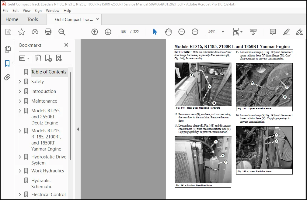
Models RT215, RT185, 2100RT, and 1850RT Yanmar Engine…………………………………..103
General Information……………………………………………………………..103
Yanmar Smartassist Connection…………………………………………………103
Engine Access…………………………………………………………………..103
Engine Maintenance………………………………………………………………103
Yanmar Engine Removal/Installation………………………………………………..103
Yanmar Engine Removal………………………………………………………..103
Yanmar Engine Installation……………………………………………………114
Fuel System Maintenance………………………………………………………….124
Engine Troubleshooting…………………………………………………………..125
Engine Error Codes…………………………………………………………..127
Yanmar Engine Diagnostic Trouble Codes (DTC)……………………………………127
Hydrostatic Drive System…………………………………………………………….135
General Information……………………………………………………………..135
General Hydraulic Service Notes…………………………………………………..135
Hydraulic Oil Analysis…………………………………………………………..135
Hydrostatic Drive Pump…………………………………………………………..135
Hydrostatic Charge Pressure Test and Adjustment…………………………………136
Hydrostatic DA Pressure Test and Adjustment…………………………………….136
Hydrostatic Pump Relief Valves……………………………………………………137
Hydrostatic Pump High Pressure Test……………………………………………138
Travel Drive Troubleshooting……………………………………………………..139
Travel Drive Joystick Lockout Valve Test……………………………………….139
Neutral Centering Check/Adjustment………………………………………………..142
Straight Tracking Adjustment……………………………………………………..143
Forward Straight Tracking Adjustment…………………………………………..144
Reverse Straight Tracking Adjustment…………………………………………..145
Hydrostatic Pump Removal and Installation………………………………………….145
Hydrostatic Pump Removal……………………………………………………..145
Hydrostatic Drive Pump Installation……………………………………………148
Hydrostatic Pump Drive Coupling Removal and Installation…………………………….151
Installation………………………………………………………………..152
Travel Motors…………………………………………………………………..152
Travel Motor Maintenance……………………………………………………..152
Travel Motor Removal/Installation……………………………………………..153
Travel Motor Removal……………………………………………………..153
Travel Motor Installation…………………………………………………155
Travel Drive High-Speed Troubleshooting……………………………………………157
Travel Drive High-Speed (Pilot) Valve Test……………………………………..157
Tracks…………………………………………………………………………160
Rubber Track Use Cautions and Tips…………………………………………….160
Sprocket Tooth Wear and Track Life…………………………………………….161
Track Replacement……………………………………………………………162
Track Removal……………………………………………………………162
IdealTrax™ Track Tensioning System…………………………………………….165
Track Tensioning Malfunctions…………………………………………………165
Track Tension Cylinder Internal Leakage Test………………………………..165
Track Tension (Pilot) Valve Test…………………………………………..166
Parking (SAHR) Brake Malfunctions…………………………………………………167
Parking Brake (Pilot) Valve Test………………………………………………167
Hydrostatic Drive System Troubleshooting…………………………………………..170
Work Hydraulics…………………………………………………………………….173
General Information……………………………………………………………..173
General Hydraulic Service Notes…………………………………………………..173
Hydraulic Oil Analysis…………………………………………………………..173
Hydraulic Hoses/Tubes………………………………………………………..174
Seals………………………………………………………………………174
Main Pressure Test and Adjustment…………………………………………………174
Main Pressure Test…………………………………………………………..174
Main Pressure Adjustment……………………………………………………..175
Hydraulic Gear Pump……………………………………………………………..176
Hydraulic Gear Pump Removal…………………………………………………..177
Hydraulic Gear Pump Installation………………………………………………178
Control Valve…………………………………………………………………..179
Main Control Valve Removal……………………………………………………180
Main Control Valve Installation……………………………………………….180
Tilt/Lift Cylinder Service/Tests………………………………………………….181
Inspection………………………………………………………………….181
Cylinder Rod/Base End Pressure Tests…………………………………………..181
Tilt Cylinder Base End Pressure Test……………………………………….181
Tilt Cylinder Rod End Pressure Test………………………………………..182
Lift Cylinder Base End Pressure Test……………………………………….182
Lift Cylinder Rod End Pressure Test………………………………………..183
Lift/Tilt Relief Pressure Adjustment…………………………………………..184
Cylinder Drift Tests…………………………………………………………185
Tilt Cylinder Drift Test………………………………………………….185
Lift Cylinder Drift Test………………………………………………….185
Cylinder Internal Leakage Tests……………………………………………….185
Tilt Cylinder Internal Leakage Test………………………………………..185
Lift Cylinder Internal Leakage Test………………………………………..186
Cylinder Cycle Time Test……………………………………………………..186
Lower the Lift Arm……………………………………………………….186
Raise the Lift Arm……………………………………………………….187
Dump the Bucket/Attachment Hitch…………………………………………..187
Roll the Bucket/Attachment Hitch Back………………………………………187
Hydraulic Cylinder Disassembly/ Assembly…………………………………………..188
Cylinder Disassembly…………………………………………………………188
Cylinder Assembly……………………………………………………………188
Bleeding Air After Cylinder Installation……………………………………….188
Work Hydraulics Tests and Solenoid Valves………………………………………….189
Hydraloc Safety Interlock Solenoid Valve Test…………………………………..189
Self-Leveling Cancel (Disable) Valve and Test…………………………………..192
Hydraglide……………………………………………………………………..194
Hydraglide/Float Valve Solenoid Test…………………………………………..194
Hydraglide Accumulator……………………………………………………….197
Solenoid Valve Disassembly/ Reassembly…………………………………………….197
Work Hydraulics Troubleshooting…………………………………………………..199
Hydraulic Schematic…………………………………………………………………201
Electrical Control System……………………………………………………………203
Electrical Control System General Information………………………………………203
CAN System General Information………………………………………………..203
Control Modules…………………………………………………………………204
Machine Control Unit (MCU)……………………………………………………204
Keypads…………………………………………………………………….207
Engine Control Unit (ECU)…………………………………………………….209
Display/Indicators/Controls…………………………………………………..209
Multi-Function Display……………………………………………………209
CAN System Service/Computer Connection…………………………………………….210
J1939 Data Connector…………………………………………………………210
CAN/Computer Connection Harnesses……………………………………………..210
Service Adapter Harness…………………………………………………..210
Yanmar Engine Connection Harness – Models RT185, RT215, 1850RT, and 2150RT……..210
Deutz Engine CAN/Computer Connection Harness (SerDia) – Models RT255/2550RT………..211
Operation/Controller Area Network (CAN) Functional Organization………………………212
Operation/CAN Function Organization Overview……………………………………212
HydralocTM (Safety Interlock) Functional Detail…………………………………213
Ignition/Starting Functional Detail……………………………………………214
Operation Functional Detail…………………………………………………..216
Lift Arm Functional Detail……………………………………………………217
Drive System Functional Detail………………………………………………..220
Auxiliary Hydraulics Functional Detail…………………………………………222
Warning Indicators Functional Detail…………………………………………..224
Lighting Functional Detail……………………………………………………226
Accessories and Options Functional Detail………………………………………….227
CAN/Control System Troubleshooting………………………………………………..231
Inputs/Outputs Detail………………………………………………………..231
Inputs Detail……………………………………………………………231
Outputs Detail…………………………………………………………..239
Indicator Lamp Troubleshooting……………………………………………………249
Electrical System…………………………………………………………………..251
Battery………………………………………………………………………..251
Power Distribution………………………………………………………………251
Power Distribution Module Fuse Socket Test……………………………………..251
Main Power Relay…………………………………………………………….252
Relay Testing……………………………………………………………….252
Machine Test…………………………………………………………….252
Bench Test………………………………………………………………252
Glow Relay Solenoid Test…………………………………………………………253
Power-A-Tach Relay Solenoid Test………………………………………………….253
Control Modules…………………………………………………………………254
Lighting……………………………………………………………………….255
Work Light Bulb Replacement…………………………………………………..255
Tail Light Bulb Replacement…………………………………………………..256
Dome Light Bulb Replacement…………………………………………………..256
Wire Harness Diagrams……………………………………………………………….257
Chassis Wire Harness Diagram – RT255 and 2550RT (Page 1 of 2)………………………..257
Chassis Wire Harness Diagram – RT255 and 2550RT (Page 2 of 2)………………………..258
Chassis Wire Harness Diagram – RT185, RT215, 1850RT, and 2150RT (Page 1 of 2)………….259
Chassis Wire Harness Diagram – RT185, RT215, 1850RT, and 2150RT (Page 2 of 2)………….260
Deutz Engine Wire Harness Diagram – RT255 and 2550RT………………………………..261
Yanmar interim Tier 4 Engine Wire Harness Diagram – RT185, RT215, 1850RT, and 2150RT……262
Yanmar Tier 4 Engine Wire Harness Diagram – RT185, RT215, 1850RT, and 2150RT…………..263
ROPS/FOPS (Cab) Wire Harness……………………………………………………..264
Operator’s Seat Wire Harness Diagram)……………………………………………..265
Rear Door Wire Harness Diagram)…………………………………………………..266
14-Pin Connector Wire Harness Diagram)…………………………………………….267
Electrical Schematics……………………………………………………………….268
Electrical Schematic – Power Distribution………………………………………….268
Electrical Schematic – Chassis……………………………………………………269
Electrical Schematic – ROPS/FOPS………………………………………………….270
Electrical Schematic – Operator’s Seat…………………………………………….271
Electrical Schematic – Rear Door………………………………………………….272
Electrical Schematic – Deutz Tier 4 Engine – RT255, and 2550RT……………………….273
Electrical Schematic – Yanmar Tier 4 Engine – RT185, RT215, 1850RT, and 2150RT…………274
Electrical Schematic – Yanmar interim Tier 4 Engine – RT185, RT215, 1850RT, and 2150RT….275
Electrical Schematic – Road Lights………………………………………………..276
Lift Arm…………………………………………………………………………..277
Lift Arm Support………………………………………………………………..277
Engage Lift Arm Support………………………………………………………277
Disengage Lift Arm Support……………………………………………………278
Lift Arm Alignment Stops…………………………………………………………279
Tilt Stop Adjustment…………………………………………………………….280
Lift Arm Removal………………………………………………………………..282
Lift Arm Installation……………………………………………………………284
ROPS/FOPS/Cab………………………………………………………………………287
Tilting ROPS/FOPS……………………………………………………………….287
Raising ROPS/FOPS……………………………………………………………287
Lowering ROPS/FOPS…………………………………………………………..288
ROPS/FOPS Removal……………………………………………………………….288
ROPS/FOPS Installation…………………………………………………………..295
HVAC System………………………………………………………………………..301
Air Conditioning Refrigerant Recovery……………………………………………..301
Air Conditioning System Port Access……………………………………………301
Air Conditioning System Charging………………………………………………….302
Index……………………………………………………………………………..303
Specifications……………………………………………………………………..307
Fluids/Lubricants Types and Capacities…………………………………………….307
Dimensions……………………………………………………………………..309
Payloads/Capacities……………………………………………………………..311
Weights………………………………………………………………………..312
Track Drive…………………………………………………………………….312
Coolant Compound Table…………………………………………………………..312
Engine…………………………………………………………………………313
Hydraulic System………………………………………………………………..315
General…………………………………………………………………….315
Drive Hydraulics…………………………………………………………….315
Pumps………………………………………………………………………316
Cylinders…………………………………………………………………..317
Forces and Cycle Times……………………………………………………….317
Electrical System……………………………………………………………….318
Sound Power/Pressure Levels………………………………………………………318
Torque Specifications……………………………………………………………….319
Customer Support: [email protected]
https://vimeo.com/801136125
PLEASE NOTE:
- This is the same manual used by the DEALERSHIPS to SERVICE your vehicle.
- The manual can be all yours – Once payment is complete, you will be taken to the download page from where you can download the manual. All in 2-5 minutes time!!
- Need any other service / repair / parts manual, please feel free to contact us at heydownloadss @gmail.com . We may surprise you with a nice offer
S.V