
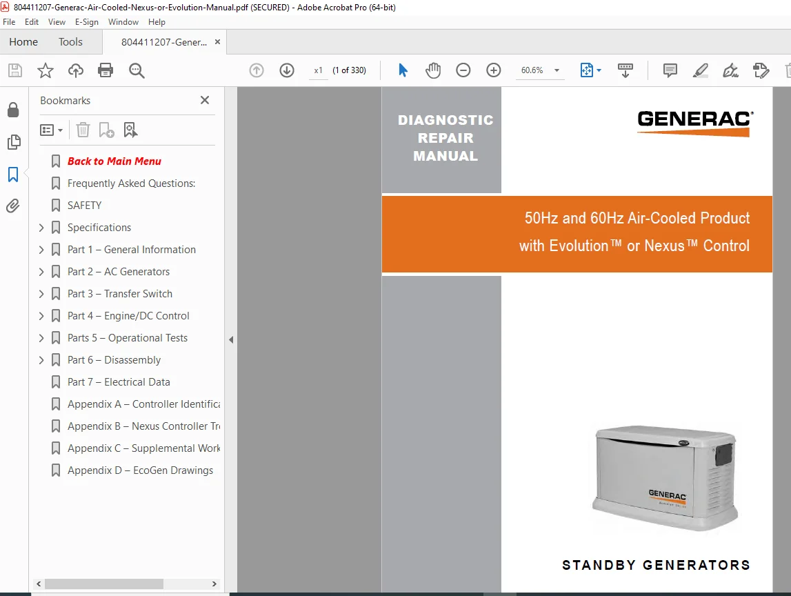
Generac Air Cooled Generator Evolution Nexus Diagnostic Repair Manual PDF
Original price was: $95.00.$16.95Current price is: $16.95.
Complete professional diagnostic and repair manual for Generac air-cooled standby generators with Evolution or Nexus controllers. Covers 6kW, 8kW, 11kW, 13kW, 14kW, 15kW, 16kW, 17kW, and 20kW models (50Hz and 60Hz). This comprehensive 330-page technical guide includes detailed troubleshooting flowcharts, diagnostic tests, error code explanations, AC generator service, transfer switch repair, engine/DC control procedures, complete disassembly instructions, and torque specifications. Essential for technicians servicing Generac residential standby power systems.
Description
Generac Air Cooled Generator Evolution Nexus Diagnostic Repair Manual PDF DOWNLOAD
DESCRIPTION
Professional Generac Standby Generator Diagnostic Repair Manual
This is the official comprehensive diagnostic and repair manual for Generac air-cooled automatic standby generators equipped with Evolution™ or Nexus™ controllers. Designed for professional generator technicians, electricians, and service engineers, this manual provides complete technical documentation for diagnosing, troubleshooting, repairing, and maintaining residential and light commercial standby power systems.
Generator Models Covered:
- 6kW Eco-Gen™ (Nexus controller, 530cc OHVI engine)
- 8kW (Evolution/Nexus, V-Twin or Single Cylinder)
- 11kW (Evolution/Nexus, V-Twin engine)
- 13kW (Evolution/Nexus, V-Twin engine)
- 14kW (Evolution/Nexus, V-Twin engine)
- 15kW (Evolution/Nexus, V-Twin engine)
- 16kW (Evolution/Nexus, V-Twin engine)
- 17kW (Evolution/Nexus, V-Twin engine)
- 20kW (Evolution/Nexus, V-Twin engine)
Frequencies: 50Hz and 60Hz models
Fuel Types: Natural Gas (NG) and Liquid Propane (LP)
Control Systems: Evolution™ and Nexus™ Controllers
Applications: Residential and light commercial automatic standby power
Complete Manual Contents:
FREQUENTLY ASKED QUESTIONS:
- Fuel supply and BTU requirements
- Gas regulator placement and distance requirements
- Full-flow rated fuel valve specifications
- Pipe sizing and flow restrictions
- Installation requirements and code compliance
- Indoor/outdoor mounting restrictions
- Electrical conduit and wiring guidelines
- Transfer switch NEMA ratings
QUICK REFERENCE GUIDE (Evolution Controllers):
- Common problem quick-diagnosis chart
- LED indicator meanings (Green, Red, Amber, None)
- Active alarm identification
- Immediate troubleshooting solutions
- Critical safety checks
- Customer-accessible fixes vs. dealer service calls
SAFETY INFORMATION:
- Comprehensive safety alerts (DANGER, WARNING, CAUTION)
- Four safety symbols explained
- Electrical shock hazards and prevention
- Fire and explosion hazards
- ESD handling procedures
- Proper use of replacement parts
- Fastener strength requirements
SPECIFICATIONS (Complete Technical Data):
- 60Hz Generator Specifications: 8kW through 20kW models
- 50Hz Generator Specifications: International models
- Evolution Controller Specifications:
- Rated voltages (120V/240V configurations)
- Maximum continuous load currents
- Main line circuit breaker ratings
- Battery requirements (Group 26R, 525 CCA minimum)
- Unit weights and dimensions
- Operating temperature ranges (-29°C to 50°C)
- Stator winding resistance values
- Rotor resistance specifications
- Nexus Controller Specifications:
- Complete electrical specifications
- Controller feature differences
- Interface specifications
- Engine Specifications:
- Generac OHVI engine details
- Cylinder displacement (410cc to 999cc)
- Recommended spark plugs and gap settings
- Starter specifications
- Oil capacity and filter part numbers
- Air filter part numbers
- Operating RPM specifications
- Power derating factors (altitude and temperature)
- Fuel Consumption Data:
- Natural Gas consumption at 1/2 load and full load
- LP consumption at 1/2 load and full load
- BTU requirements per hour
PART 1: GENERAL INFORMATION (31 Pages)
Section 1.1 – Generator Basics:
- Introduction to Generac standby systems
- Component identification and functions
- Generator identification label interpretation
- Data label reading and serial number location
Section 1.2 – Installation Basics:
- Fuel supply requirements and specifications
- Natural Gas fuel interconnection procedures
- LP tank sizing and placement
- Fuel pressure requirements
- Regulator installation and setup
Section 1.3 – Preparation Before Use:
- Reconfiguring fuel systems (Evolution controllers)
- Reconfiguring fuel systems (Nexus controllers)
- Fuel type conversion procedures (NG to LP, LP to NG)
- Initial startup preparations
Section 1.4 – Measuring Electricity:
- VOM (Volt-Ohm Meter) Usage:
- Measuring AC voltage correctly
- Measuring DC voltage procedures
- AC frequency measurement
- Current measurement techniques
- Resistance measurement procedures
- Electrical Units Explained:
- Volts, amps, watts, ohms
- Ohm’s Law applications
- Practical calculations for troubleshooting
Section 1.5 – Testing, Cleaning and Drying:
- Visual inspection procedures
- Megohmmeter (Megger) usage
- Insulation resistance testing
- Cleaning the generator (proper methods)
- Drying generator components after water exposure
Section 1.6 – Operating Instructions:
- User interface navigation (Evolution and Nexus)
- Selecting automatic operation mode
- Manual operation procedures
- Control panel button functions
- LED indicator interpretation
Section 1.7 – Automatic Operating Parameters:
- Utility failure detection sequence
- Cranking procedures and timing
- Cranking conditions and safety shutdowns
- Load transfer parameters and timing
- Utility restored sequence
- Cool-down and shutdown procedures
Section 1.8 – General Maintenance:
- Maintenance message interpretation
- Air filter service and replacement
- Spark plug service and specifications
- Visual inspection checklists
- Corrosion protection procedures
- Valve clearance checking and adjustment
- Battery maintenance and testing
Section 1.9 – Wireless Remote:
- Wireless Monitor setup and operation
- Basic wireless troubleshooting
- Wireless Advanced Module features
- Advanced wireless troubleshooting
- Mobile Link™ System:
- Remote monitoring capabilities
- Smartphone app integration
- Alert notifications
- Mobile Link troubleshooting procedures
Section 1.10 – Evolution Control Panel Menu System:
- Main menu navigation
- Evolution Dealer menu access
- Password-protected functions
- Configuration settings
- Advanced programming options
Section 1.11 – Nexus Control Panel Menu System:
- Main menu navigation (Nexus-specific)
- Menu structure differences from Evolution
- Service technician access procedures
Section 1.12 – General Troubleshooting Guidelines:
- Recommended tools for diagnostics
- Troubleshooting reminders and best practices
- Important notes concerning connectors
- Systematic diagnostic approach
PART 2: AC GENERATORS (32 Pages)
Section 2.1 – Description and Components:
- Engine-generator drive system explanation
- Alternator assembly construction
- Brushless excitation system
- Rotor and stator windings
- Automatic voltage regulator (AVR)
- Power winding configurations
- Sensing winding circuits
Section 2.2 – Operational Analysis:
- Field boost operation and purpose
- Voltage regulation principles
- Load response characteristics
- Frequency control mechanisms
Section 2.3 – Troubleshooting Flowcharts:
- Systematic AC troubleshooting procedures
- Decision trees for common AC problems
- Step-by-step diagnostic paths
Section 2.4 – Diagnostic Tests (15 Comprehensive Tests):
- Test 1: Check AC Output Voltage
- Test 3: Calibrate Voltage (Evolution/Nexus)
- Test Wire 4: Evolution/Nexus voltage regulator testing
- Test Wire 4A: Evolution-specific tests
- Diode Tests: Evolution and Nexus rotating diode testing
- Test 4: Fixed Excitation Test / Rotor Amp Draw Test
- Test 5: Test Sensing Circuit Wires 11 and 44
- Test 6: Test Excitation Winding Circuit 2 and 6
- Test 7: Test Stator With VOM (resistance checks)
- Test 8: Resistance Check of Rotor Circuit
- Test 9: Check Brushes and Slip Rings
- Test 10: Test Rotor Assembly (rotation and balance)
- Test 11: Check AC Output Frequency
- Test 12: Check Stepper Motor Control
- Test 14: Check Voltage and Frequency Under Load
- Test 15: Check for Overload Condition
- Test 16: Check Engine Condition
- Test 17: Calibrating Current to Evolution Current Transformers
PART 3: TRANSFER SWITCH (40 Pages)
Section 3.1 – Description and Components:
- Transfer switch enclosure construction
- Transfer switch contactor operation
- Transfer relay function and operation
- Neutral lug connections
- Manual transfer handle mechanism
- Customer connection terminals (Load and Line)
- Fuse Holder: F1, F2, F3 fuse locations and ratings
- Load Shed Module (LSM):
- 120 Volt LSM operation
- OPCB 24/120 Volt module operation
- Load shedding sequence
- Priority load management
- Power Supply Connections for Contactors
- Control of Separate Contactor (external loads)
- Power Management Module operation
Section 3.2 – Operational Analysis:
- Transfer switch logic and timing
- Utility sensing and monitoring
- Generator sensing and verification
- Transfer timing sequences
- Position feedback mechanisms
Section 3.3 – Troubleshooting Flowcharts:
- Transfer switch problem diagnosis trees
- Systematic troubleshooting procedures
Section 3.4 – Diagnostic Tests (17 Comprehensive Tests):
- Test 20: Check Voltage at Terminal Lugs E1 and E2
- Test 21: Check Manual Transfer Switch Operation
- Test 22: Check 23 and 194 Circuit
- Test 23: Test Transfer Relay
- Test 24: Test Standby Control Circuit
- Test 25: Check Wire 23
- Test 26: Test Utility Control Circuit
- Test 27: Test Limit Switches
- Test 28: Check Fuses F1 and F2
- Test 29: Check Fuse F3
- Test 30: Check Main Circuit Breaker
- Test 32: Check N1 and N2 Wiring
- Test 33: Check N1 and N2 Voltage
- Test 34: Check Utility Sensing Voltage at Circuit Board
- Test 35: Check Utility Sense Voltage
- Test 36: Check T1 Wiring
PART 4: ENGINE/DC CONTROL (76 Pages)
Section 4.1 – Description and Components:
- Controller architecture (Evolution and Nexus)
- LED display functions and indicators
- Battery charger operation and specifications
- Fuse locations and ratings (7.5 Amp main fuse)
- Starter contactor relay/solenoid operation
- Common alarm relay functions
- Circuit Pin Descriptions: Complete connector pinouts
- Menu system navigation for technicians
Section 4.2 – Engine Protective Devices:
- Low Battery Warning – Detection and response
- Low Oil Pressure (Evolution E-Code 1300) – Switch operation
- High Temperature Switch (Evolution E-Code 1400) – Protection logic
- Overspeed Protection – Governor control
- RPM Sensor Failure (Evolution E-Codes 1501, 1505, 1511, 1515)
- Overcrank Protection (Evolution E-Code 1100) – Causes and solutions
- Under-Frequency Protection – Load shedding triggers
- Clearing Alarm Procedures – Reset methods for each alarm type
Section 4.3 – Operational Analysis:
- Controller operation logic flowcharts
- Starting sequence timing diagrams
- Running operation monitoring
- Shutdown sequence analysis
- Alarm condition handling
Section 4.4 – Troubleshooting Flowcharts:
- Engine starting problems
- Running problems
- Shutdown problems
- Control system failures
Section 4.5 – Diagnostic Tests (43 Comprehensive Tests):
- Test 40: Check Position of Auto-Off-Manual Mode
- Test 41: Try Manual Start
- Test 42: Test Function of Auto-Off-Manual Mode
- Test 43: Test Auto Operations (Evolution and Nexus)
- Test 44: Check 7.5 Amp Fuse (Evolution Alarm Code 2400)
- Test 45: Check Battery (voltage and load test)
- Test 46: Check Wire 56 Voltage
- Test 47: Test Starter Contactor Relay (V-Twin Only)
- Tests 48-82: Complete diagnostic test suite covering:
- Ignition system testing
- Fuel system verification
- Governor operation
- Oil pressure switch testing
- Temperature switch verification
- Wiring continuity checks
- Valve clearance adjustment
- Exercise function testing
- Cranking and running circuits
- Transfer relay operation
- Low-speed function testing
- Choke solenoid testing (Nexus)
- Controller voltage outputs
- Battery charging system
- T1 voltage verification throughout system
- F3 fuse circuit testing
PART 5: OPERATIONAL TESTS (3 Pages)
Section 5.1 – System Functional Tests:
- Manual transfer switch operation verification
- System voltage tests under various conditions
- Generator tests under load
- Testing automatic operation sequence
Section 5.2 – Setup Procedures:
- Setting Exercise Time:
- Exercise timer programming
- 7-day automatic exercise setup
- 12-minute exercise cycle explanation
- Activation Process:
- Generator activation requirements
- Obtaining activation codes (web and phone)
- Installation wizard navigation
- Fuel type selection (Evolution units)
- Language selection
- Passcode entry procedures
- Time/date setup
- Troubleshooting activation problems
PART 6: DISASSEMBLY (137 Pages)
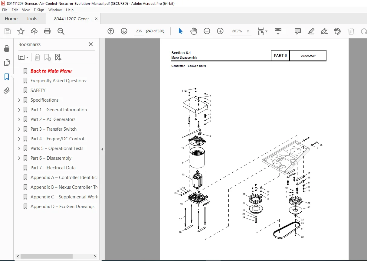
Section 6.1 – Major Disassembly:
Safety Procedures:
- Controller shutdown procedures
- 7.5 amp main fuse removal
- Transfer switch fuse removal (N1, N2)
- Fuel supply shutdown
- Utility power disconnection
Front Engine Access:
- Controls cover removal (Torx T-27)
- Evolution controller removal procedures
- Nexus controller removal procedures
- Control harness disconnection
- Stator wire removal from circuit breaker
- Control wire removal (N1, N2, T1, 0, 194, 23)
- GFCI outlet disconnection
- Status light removal
- Controller mounting box removal
- Engine intake baffle removal
Major Disassembly Procedures:
- Complete step-by-step disassembly instructions
- Component removal sequences
- Proper handling procedures
- Parts identification during disassembly
- Assembly notes and critical alignments
- Wire routing documentation
- Connector identification
Torque Requirements:
- Comprehensive torque specification tables
- Fastener identification
- Critical torque values for reassembly
- Thread locker requirements
- Gasket and seal installation specs
Complete Engine Disassembly:
- Cylinder head removal
- Valve train disassembly
- Piston and connecting rod removal
- Crankshaft removal procedures
- Governor disassembly
- Oil pump removal
- Ignition system component removal
- Fuel system component removal
Alternator Disassembly:
- Rotor removal from shaft
- Stator removal from housing
- Bearing replacement procedures
- Brush assembly service
- Slip ring cleaning and inspection
Detailed Component Removal:
- Oil filter and oil drain procedures
- Air filter housing removal
- Muffler and exhaust system
- Fuel regulator and solenoid
- Battery tray and connections
- All sensors and switches
- Wiring harness routing guides
File Details:
- Manual Title: Diagnostic Repair Manual
- Application: 50Hz and 60Hz Air-Cooled Product with Evolution™ or Nexus™ Control
- Models Covered: 6kW through 20kW Generac Standby Generators
- Controllers: Evolution and Nexus (Also known as Sync 1.0/2.0 for Honeywell-branded units)
- PDF Quality: High-resolution professional service manual
- Total Pages: 330 pages
- Language: English
- File Format: Searchable PDF with detailed diagrams, flowcharts, and wiring schematics
Special Features:
Comprehensive Troubleshooting Flowcharts: Over 25 decision-tree flowcharts guiding technicians from symptom to root cause, eliminating guesswork and reducing diagnostic time.
82+ Diagnostic Tests: Step-by-step test procedures with exact voltage specifications, resistance values, and pass/fail criteria for every electrical component and circuit.
Complete Error Code Database: Evolution E-Code explanations with specific diagnostic procedures and repair solutions for every alarm condition (1100, 1300, 1400, 1501, 1505, 1511, 1515, 2400, and more).
Dual Controller Coverage: Parallel procedures for both Evolution and Nexus controllers, including differences in testing, programming, and troubleshooting approaches.
Activation and Programming: Complete instructions for generator activation, exercise timer setup, wireless monitoring, and Mobile Link™ remote monitoring system configuration.
Professional-Grade Specifications: Exact resistance values for stator windings, rotor circuits, torque specifications, and fuel consumption data for accurate diagnostics and proper reassembly.
Safety-First Approach: Comprehensive safety procedures integrated throughout the manual, with DANGER, WARNING, and CAUTION alerts protecting technicians during high-voltage and fuel system service.
Why This Manual is Essential for Generator Service:
This diagnostic repair manual is the complete professional resource for anyone servicing Generac air-cooled standby generators. Whether you’re an electrical contractor installing and maintaining generator systems, a service technician performing warranty repairs, or a generator service business owner, this manual provides the authoritative technical documentation required for professional-quality diagnostics and repairs.
Download immediately and gain instant access to 330 pages of manufacturer-approved diagnostic procedures, complete wiring diagrams, error code explanations, component specifications, and step-by-step disassembly instructions that will transform complex generator problems into systematic, profitable repairs. Reduce callbacks, increase first-call fix rates, and establish yourself as the local expert in Generac standby power systems!