
Generac Standby Prime Electric Power Systems All Series Diagnostic Repair Manual
Original price was: $44.95.$27.95Current price is: $27.95.
Comprehensive diagnostic and repair manual for Generac Standby/Prime Electric Power Systems covering all series. Includes troubleshooting flow charts, diagnostic tests, wiring diagrams, governor adjustment procedures, and complete service information for direct excited, brushless, and Marathon AC generators.
Description
Generac Standby Prime Electric Power Systems All Series Diagnostic Repair Manual
This Generac Standby Prime Electric Power Systems All Series Diagnostic Repair Manual is the definitive service guide for technicians working on Generac standby and prime electric power systems. Covering every series produced at the time of publication, this manual provides the systematic troubleshooting, testing, and repair procedures needed to diagnose and correct faults in direct excited, brushless, and Marathon AC generators, along with their associated control consoles and transfer switch options.
File Details
- Manual Type: Diagnostic Repair Manual
- Brand: Generac Corporation
- Models Covered: Standby/Prime Electric Power Systems, All Series
- Language: English
- File Format: PDF
- Revision: Revision 4 (11/07/96)
- Publication Date: 1996
Chapters Covered
- Part 1: Introduction to Standby Electric Power Systems
- 1.1 Standby Generator Identification
- 1.2 Types of Stator Connection Systems
- 1.3 Standby Electric System Familiarization
- 1.4 Generator Maintenance and Testing
- 1.5 Mechanical Engine Governors
- 1.6 Electronic Engine Governors
- 1.7 Diesel Engine Governors
- Part 2: Direct Excited AC Generators
- 2.1 Description and Components
- 2.2 Operational Analysis
- 2.3 Troubleshooting Flow Charts
- 2.4 Diagnostic Tests
- Part 3: Brushless AC Generators
- 3.1 Description and Components
- 3.2 Operational Analysis
- 3.3 Troubleshooting Flow Charts
- 3.4 Diagnostic Tests
- 3.5 Insulation Resistance Tests
- 3.6 Permanent Magnet Generators
- 3.7 Testing PMG Units
- Part 4: “Marathon” AC Generators
- 4.1 Description and Components
- 4.2 Operational Analysis
- 4.3 Generator Lead Connections
- 4.4 Maintenance, Cleaning and Drying
- 4.5 Disassembly
- 4.6 Inspection
- 4.7 Reassembly
- 4.8 Troubleshooting Flow Charts
- 4.9 Generator Testing
- 4.10 Specifications
- Part 5: Options A & B Control Consoles
- 5.1 Meters, Gauges and Controls
- 5.2 Internal Console Components
- 5.3 AC Circuits Operation
- 5.4 DC Control-12 Volts Gas Units
- 5.5 DC Control-12 Volts Diesel Units
- 5.6 DC Control-24 Volts Diesel Units
- 5.7 Troubleshooting Charts
- 5.8 Diagnostic Tests
- 5.9 Dual 12 or 24 Volts DC Control
- Part 6: Option C Control Console
- 6.1 Meters, Gauges and Controls
- 6.2 Engine Monitor Panel
- 6.3 Internal Console Components
- 6.4 AC Circuits Operation
- 6.5 DC Control-12 Volts Gas Units
- 6.6 DC Control-12 Volts Diesel Units
- 6.7 DC Control-24 Volts Diesel Units
- 6.8 Troubleshooting Charts
- 6.9 Diagnostic Tests
- 6.10 Dual 12 or 24 Volts DC Control
- Part 7: Generator Options & Accessories
- 7.1 Generator Strip Heaters
- 7.2 Voltage Changeover Boards
- 7.3 The 3-Lamp Remote Annunciator
- 7.4 The 5-Lamp Remote Annunciator
- 7.5 The 14-Lamp Remote Annunciator
- 7.6 The 18-Lamp Remote Annunciator
- Part 8: “Y-Type” Automatic Transfer Switches
- Part 9: “Wn” Type Automatic Transfer Switches
- Part 10: The “CPU” Type Intelligence System
- Part 11: The “Logic” Type Intelligence System
- Part 12: Transfer Switch Options
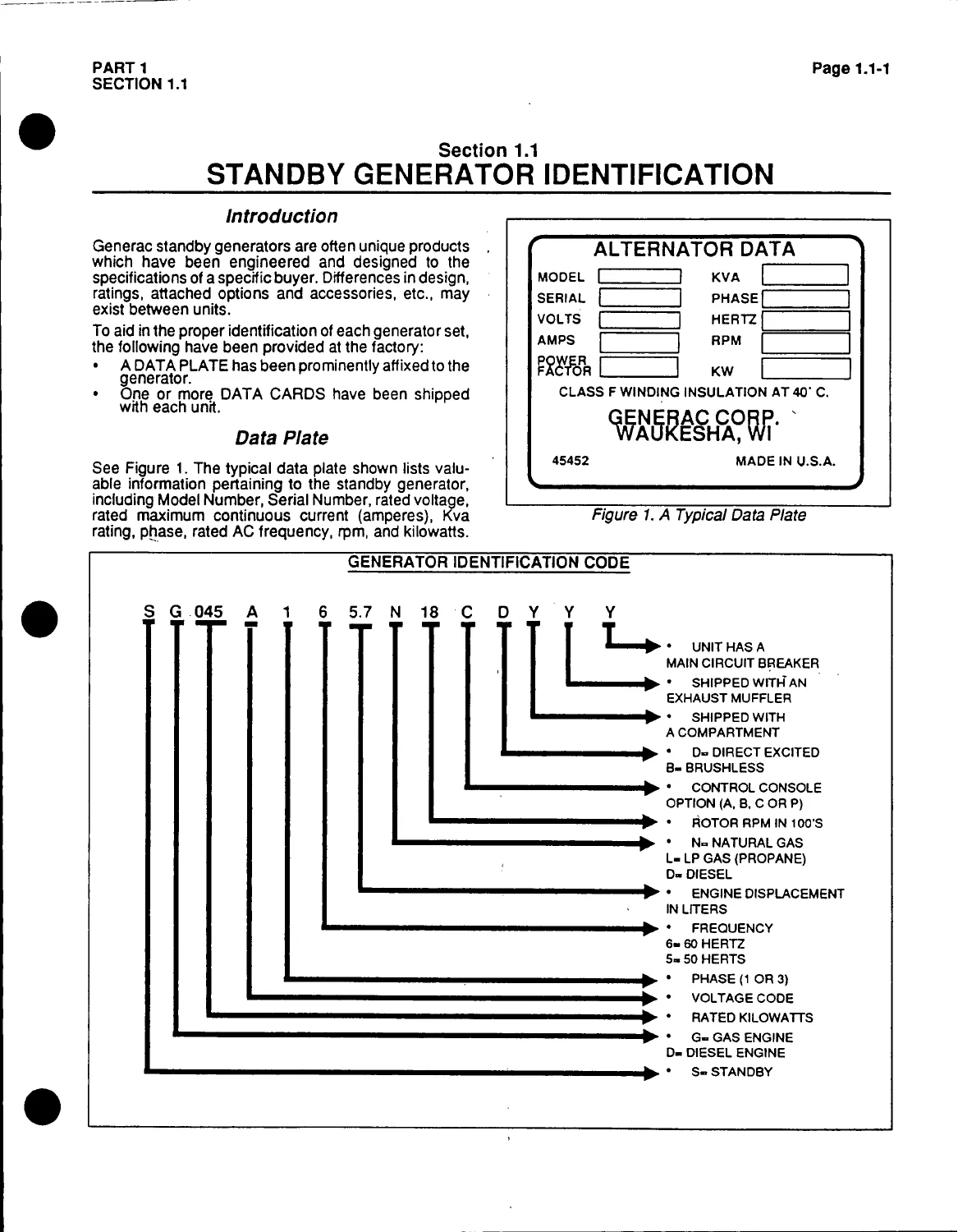
This Generac Standby Prime Electric Power Systems All Series Diagnostic Repair Manual goes far beyond a simple wiring diagram collection. It opens with a detailed generator identification system that decodes model numbers by engine type, displacement, frequency, phase, voltage code, and kilowatt rating, so you can pinpoint exactly which unit you are working on before turning a wrench. The stator connection systems chapter covers dual winding, parallel wye, series wye, delta, zig-zag, and multi-voltage changeover board configurations, with lead numbering and connection charts for each. Generator maintenance and testing procedures include insulation resistance testing with hi-pot and megohmmeter, stator and rotor testing, and brushless exciter testing.
Governor coverage is unusually thorough, spanning mechanical governors (Part Nos. 65934 and 68985), electronic governors (Barber-Colman DYNA-MASTER and DYNA 8000 systems, plus Generac’s own electronic and stepper motor governors), and diesel injection pump governors. Each governor section provides adjustment procedures with specific frequency targets, droop settings, and stability tuning steps.
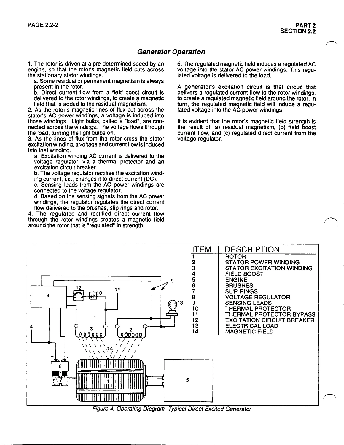
The generator-specific sections break down the three major AC generator families used across the Generac standby lineup. Direct excited generators receive full coverage of brushes, slip rings, voltage regulators, field boost circuits, and excitation winding diagnostics. Brushless generators are covered in equal depth, including exciter stator, exciter rotor, rotating rectifier, and PMG (permanent magnet generator) variants. The Marathon AC generator section addresses the larger 100–350 kW units with their step-down transformer excitation system and rotating rectifier assembly.
Control console coverage spans Options A, B, and C. The Option C section includes the engine monitor panel with its five fault advisory lamps, the test/reset switch, and the calibration procedure for the DC control/latch-crank circuit board’s overspeed shutdown. DC control systems are broken down by voltage and fuel type: 12-volt gas, 12-volt diesel, 24-volt diesel, and the later dual 12/24-volt systems that eliminated the need for a DC converter.
What This Manual Helps You Do
- Identify any Generac standby generator by model, serial, voltage code, and engine type
- Diagnose no-output, low-voltage, high-voltage, and residual-voltage conditions using structured troubleshooting flow charts
- Test and replace voltage regulators, excitation circuit breakers, thermal protectors, and DPE windings
- Adjust mechanical, electronic, and diesel engine governors to correct frequency and voltage drift
- Perform insulation resistance tests on stators, rotors, exciters, and PMG windings
- Service Option A, B, and C control consoles, including engine monitor panels and fault shutdown circuits
- Interpret stator connection diagrams for 1-phase and 3-phase systems at all available voltage codes
- Repair and maintain Y-Type, Wn Type, CPU Type, and Logic Type automatic transfer switches
Why This Manual Matters
Standby power systems are life-safety equipment. When the utility drops out, the generator must start, transfer, and carry the load without hesitation. That reliability depends on correct maintenance and accurate diagnosis when something goes wrong. The Generac Standby Prime Electric Power Systems All Series Diagnostic Repair Manual gives you the same procedural flow charts, diagnostic tests, and specification data used to service these units across all series and control console options. Without the correct lead numbering, voltage code tables, and governor adjustment targets, you risk miswiring a reconnectable stator, over-exciting a voltage regulator, or leaving a governor set to the wrong frequency.
IMAGES PREVIEW
Instant PDF Delivery
This Generac diagnostic repair manual is delivered as an instant PDF download after purchase. No shipping, no waiting. The file can be viewed on any computer, tablet, or smartphone and printed for use in the shop or at the generator site. Whether you are servicing a single standby unit or maintaining a fleet, this manual puts the complete diagnostic and repair procedures at your fingertips.
Reviews
There are no reviews yet.