Grove Crane RT 700E Series Carrier Operator’s and Safety Handbook Manual
$16.95
The Grove Crane RT 700E Series Carrier Operator’s and Safety Handbook Manual is an essential guide, offering comprehensive instructions and safety protocols for efficient operation of the RT 700E carrier model. Accessible as a manual, it ensures safe and effective usage.
Description
Grove Crane RT 700E Series Carrier Operator’s and Safety Handbook Manual – PDF DOWNLOAD
FILE DETAILS:
Grove Crane RT 700E Series Carrier Operator’s and Safety Handbook Manual – PDF DOWNLOAD
Language : English
Pages : 88
Downloadable : Yes
File Type : PDF
TABLE OF CONTENTS:
Grove Crane RT 700E Series Carrier Operator’s and Safety Handbook Manual – PDF DOWNLOAD
Section 1 – INTRODUCTION
GENERAL 1-1
NOISE VIBRATION TEST RESULTS 1-1
Section 2: SAFETY PRECAUTIONS
GENERAL 2-1
OPERATOR’S INFORMATION 2-1
OPERATOR’S QUALIFICATIONS 2-2
CRANE STABILITY/STRUCTURAL STRENGTH 2-3
Load Charts 2-3
Work Site 2-4
Lifting Operations 2-4
Counterweight 2-6
Multiple Crane Lifts 2-6
LOAD MOMENT INDICATING SYSTEMS 2-6
Two-Blocking 2-6
Work Area Definition System 2-7
ELECTROCUTION HAZARD 2-7
Set Up and Operation 2-8
Electrocution Hazard Devices 2-8
Electrical Contact 2-9
Special Operating Conditions and Equipment 2-9
CRUSHING HAZARDS 2-10
PERSONNEL HANDLING 2-11
TRAVEL OPERATION 2-11
MAINTENANCE 2-12
Service and Repairs 2-12
Lubrication 2-13
Tires 2-13
Wire Rope 2-13
BATTERIES 2-14
ENGINE 2-15
WORK PRACTICES 2-15
Crane Access 2-15
Job Preparation 2-15
Working 2-15
Lifting 2-16
Hand Signals 2-17
TRANSPORTING THE CRANE 2-17
SHUTDOWN 2-17
BOOM EXTENSION/JIB 2-18
COLD WEATHER OPERATION 2-19
Section 3 – CAB CONTROLS AND INDICATORS
ENGINE CONTROLS AND INDICATORS 3-1
Hand Throttle Lock Control 3-1
Engine Oil Pressure Gauge 3-1
Transmission Oil Temperature Gauge 3-1
Fuel Gauge 3-1
Voltmeter 3-1
Ignition Switch 3-1
Tachometer 3-4
V
TABLE OF CONTENTS (CONTINUED)
Page
Engine Coolant Temperature Gauge 3-4
Foot Throttle Pedal 3-4
Drivetrain Distress Indicator 3-4
Hourmeter (Not Shown) 3-4
CRANE CONTROLS AND INDICATORS 3-4
Crane Function Power Switch 3-4
Transmission Shift Lever 3-4
Telescope or Auxiliary Hoist Control Lever 3-4
Swing Control Lever 3-4
Rear Steer Control Switch 3-4
Rear Wheels Not Centered Indicator 3-5
Main Hoist Speed Selector Switch 3-5
Auxiliary Hoist Speed Selector Switch (Optional) 3-5
Auxiliary Hoist Switch (Optional) 3-5
Boom Lift Control Lever 3-5
Main Hoist Control Lever 3-5
Telescope Control Pedal (Optional) 3-5
Hydraulic Boost Switch 3-5
Hoist 3rd Wrap Indicator (Optional w/CE) 3-5
Hoist Rotation Indicators 3-5
Transmission Range Selector Switch 3-5
Differential Lock Control Switch (Optional) 3-6
Outrigger Selector Panel 3-6
Outrigger Extend/Retract Switch 3-6
Swing Brake Control Switch 3-6
Swing Brake Pedal 3-6
Brake Foot Pedal 3-6
Main Brake Fail Indicator 3-6
Park Brake Control Switch 3-6
Pin Swing Lock Control (Pin Type) 3-7
360 Degree Swing Lock Control (Positive Lock Type) (Optional) 3-7
Load Moment Indicating (LMI) and Work Area Definition System Control Panel 3-7
ACCESSORY CONTROLS AND INDICATORS 3-7
Headlights Switch 3-7
Boom Light Switch (Optional} 3-7
Work Light Switch 3-7
Cab Circulating Fan 3-7
Horn 3-7
Backup Alarm (Not Shown) 3-7
Turn Signal Lever and Windshield Wiper/Washer Controls 3-7
Hazard Lights Switch 3-7
Right Turn Signal Indicator 3-8
Left Turn Signal Indicator 3-8
Cab Dome Light 3-8
Skylight Wiper (Not Shown) 3-8
Bubble Level Indicator 3-8
Heat Control Knob 3-8
Fan Switch 3-8
Defroster Switch 3-8
Air Conditioning Control Switch (Optional) 3-8
Spotlight (Optional) 3-8
Beacon Light (Optional) (Not Shown) 3-8
Fire Extinguisher 3-8
Defroster Fan 3-8
Windshield Wiper 3-8
12 VDC Accessory Outlet 3-9
Circuit Breaker Panel 3-9
Section 4 – OPERATING PROCEDURES
PRE-STARTING CHECKS 4-1
Fuel Supply 4-1
Engine Oil 4-1
Engine Coolant 4-1
Batteries 4-1
Signal and Running Lights 4-1
Foot and Parking Brakes 4-1
Daily Lubrication 4-1
Hydraulic Reservoir and Filter 4-1
Tires 4-1
Wire Rope 4-1
Hook Block 4-1
Air Cleaner 4-1
COLD WEATHER OPERATION 4-1
Operation Below -40°C 4-2
Operation Below -40°F 4-2
ENGINE OPERATION 4-2
Starting Procedure 4-2
Cold Weather Starting 4-2
Idling the Engine 4-3
Racing the Engine 4-3
Shutdown Procedure 4-3
CRANE TRAVEL OPERATION 4-3
Traveling – General 4-3
Traveling With Boom Extension Erected 4-4
Extended Travel 4-4
Moving the Crane 4-4
Steering 4-4
Front Wheel Steering 4-5
Rear Wheel Steering 4-5
Four Wheel Steering 4-5
Crabbing 4-5
Traveling – Forward 4-5
Traveling – Reverse 4-5
Four-Wheel Drive Operation 4-6
Proper Operation Of Differential Lock 4-6
General 4-6
Operation 4-6
Proper Operation Of Axle Oscillation Lockouts 4-7
GENERAL CRANE OPERATION 4-7
Pump Drive 4-7
Setting the Park Brake When Crane is on Outriggers 4-7
Control Lever Operation 4-7
Preload Check 4-8
USING YOUR LOAD CHART 4-8
CRANE FUNCTIONS 4-9
Setting the Outriggers 4-9
Engaging the Mid-Extend Lock Pin 4-10
Stowing the Outriggers 4-10
Stowing the Mid-Extend Lock Pin 4-10
Swinging the Boom 4-11
Elevating and Lowering the Boom 4-11
Elevating the Boom 4-11
Lowering the Boom 4-11
Telescoping the Boom 4-11
Extending the Boom 4-11
Retracting the Boom 4-12
Telescope Control Pedal 4-12
Lowering and Raising the Cable 4-12
Lowering the Cable 4-12
Raising the Cable 4-12
Hoist Speed Range Selection 4-12
Operational Aids 4-12
Load Moment Indicator (LMI) System 4-12
Control Lever Lockout System 4-13
Stowing and Parking 4-13
Section 5 – LUBRICATION
GENERAL 5-1
LU RI CANTS 5-1
LUBRICATION POINTS 5-3
WIRE ROPE LUBRICATION 5-9
Section 6 – SET-UP AND INSTALLATION PROCEDURES
GENERAL 6-1
INSTALLING CABLE ON THE HOIST 6-1
CABLE REEVING 6-1
DEAD-END RIGGING/WEDGE SOCKETS 6-6
Installing Wedge and Socket 6-6
ERECTING AND STOWING THE SWINGAWAY BOOM EXTENSION 6-8
Erecting 6-8
Stowing 6-15
Setting The Folding Swingaway Offset 6-16
ERECTING AND STOWING THE SWINGAWAY BOOM EXTENSION USING THE 6 1 M (20 FOOT) INSERT 6-17
Erecting 6-17
Stowing 6-19
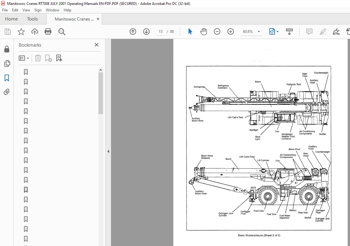
Basic Nomenclature 1-2
Cab Controls and Indicators 3-2
Terms to Know 4-8
Lubrication Chart 5-4
Installing the Cable Anchor Wedge 6-1
Reeving 6-2
Quick Reeving Hook Block 6-6
Installing Wedge and Socket 6-6
Configurations for Dead-Ending Wire Rope 6-8
Boom Extension Stop Block 6-8
Erecting and Stowing the Swingaway Boom Extension 6-9
Boom Extension Stop Block 6-16
Erecting And Stowing The Swingaway Boom Extension Using The 6 1 M (20 Foot) Insert 6-18
Wind Velocity Chart 2-5
Wire Rope Clip Torque Values 6-7
IMAGES PREVIEW OF THE MANUAL:
S.M