Grove Crane RT 890E Warm up Supplement Operator Manual 307-07 – PDF DOWNLOAD
$28.95
Grove Crane RT 890E Warm up Supplement Operator Manual 307-07 – PDF DOWNLOAD
Description
Grove Crane RT 890E Warm up Supplement Operator Manual 307-07 – PDF DOWNLOAD
FILE DETAILS:
Grove Crane RT 890E Warm up Supplement Operator Manual 307-07 – PDF DOWNLOAD
Language : English
Pages : 182
Downloadable : Yes
File Type : PDF
IMAGES PREVIEW OF THE MANUAL:
Contact us: [email protected]
https://vimeo.com/854325748?share=copy
DESCRIPTION:
Grove Crane RT 890E Warm up Supplement Operator Manual 307-07 – PDF DOWNLOAD
SAFETY INFORMATION:
General:
- The importance of safe operation and maintenance cannot be over emphasized. Carelessness or neglect on the part of operators, job supervisors and planners, rigging personnel, and job site workers can result in their death or injury and costly damage to the crane and property.
- To alert personnel to hazardous operating practices and maintenance procedures, safety messages are used throughout the manual. Each safety message contains a safety alert symbol and a signal word to identify the hazard’s degree of seriousness.
- It is impossible to compile a list of safety precautions covering all situations. However, there
are basic principles that MUST be followed during your daily routine. Safety is YOUR PRIMARY
RESPONSIBILITY, since any piece of equipment is only as safe AS THE PERSON AT THE
CONTROLS. - This information has been provided to assist in promoting a safe working atmosphere for yourself and those around you. It is not meant to cover every conceivable circumstance which could arise. It is intended to present basic safety precautions that should be followed in daily operation
- Because you, the operator, are the only part of the crane that can think and reason, your
responsibility is not lessened by the addition of operational aids or warning devices. Indeed, you
must guard against acquiring a false sense of security when using them. They are there to assist,
not direct the operation. Operational aids or warning devices can be mechanical, electrical,
electronic, or a combination thereof. They are subject to failure or misuse and should not be
relied upon in place of good operating practices. - You, the operator, are the only one who can be relied upon to assure the safety of yourself and
those around you. Be a PROFESSIONAL and follow the RULES of SAFETY. - REMEMBER, failure to follow just one safety precaution could cause an accident that results in
death or serious injury to personnel or damage to equipment. You are responsible for the safety of
yourself and those around you.
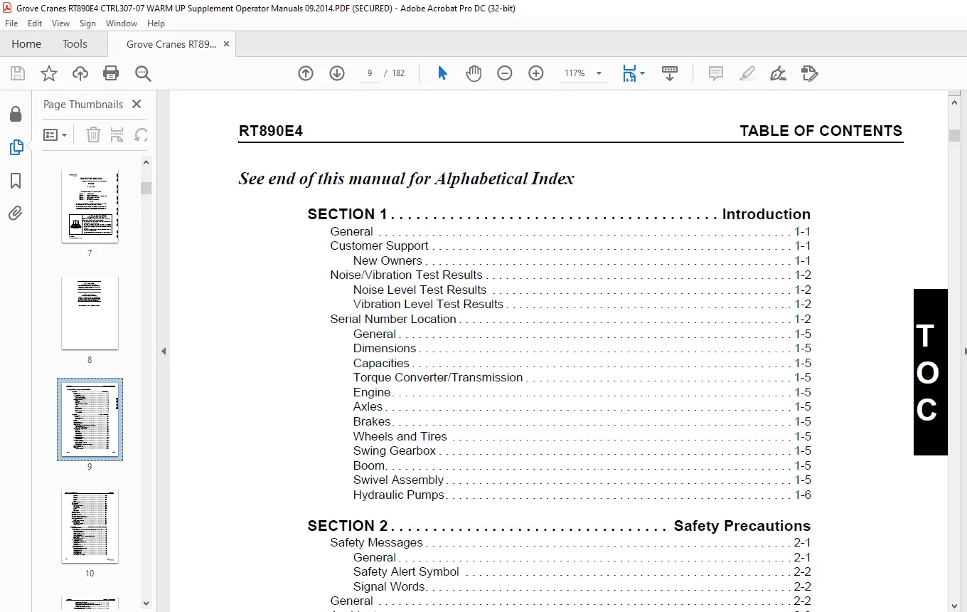
TABLE OF CONTENTS:
Grove Crane RT 890E Warm up Supplement Operator Manual 307-07 – PDF DOWNLOAD
SECTION 1 Introduction
General 1-1
Customer Support 1-1
New Owners 1-1
Noise/Vibration Test Results 1-2
Noise Level Test Results 1-2
Vibration Level Test Results 1-2
Serial Number Location 1-2
General 1-5
Dimensions 1-5
Capacities 1-5
Torque Converter/Transmission 1-5
Engine 1-5
Axles 1-5
Brakes 1-5
Wheels and Tires 1-5
Swing Gearbox 1-5
Boom 1-5
Swivel Assembly 1-5
Hydraulic Pumps 1-6
SECTION 2 Safety Precautions
Safety Messages 2-1
General 2-1
Safety Alert Symbol 2-2
Signal Words 2-2
General 2-2
Accidents 2-2
Operator Information 2-2
Operator Qualifications 2-3
Operational Aids 2-4
Rated Capacity Limiter (RCL) Systems (If Equipped) 2-4
Anti-Two-Blocking Device 2-4
Working Area Limiter (If Equipped) 2-5
Crane Stability/Structural Strength 2-5
Load Charts 2-6
Work Site 2-6
Wind Forces 2-6
Lifting Operations 2-7
Counterweight 2-8
Outrigger Lift Off 2-8
Multiple Crane Lifts 2-8
Pile Driving and Extracting 2-9
Crane Equipment 2-9
Crane Inspection 2-9
Electrocution Hazard 2-9
Set-Up and Operation 2-11
Electrocution Hazard Devices 2-11
Electrical Contact 2-12
Special Operating Conditions and Equipment 2-12
Personnel Handling 2-12
Environmental Protection 2-13
Maintenance 2-13
Service and Repairs 2-14
TABLE OF CONTENTS RT890E4
TOC-2
Lubrication 2-15
Tires 2-15
Wire Rope 2-15
Sheaves 2-16
Batteries 2-17
Engine 2-17
Transporting the Crane 2-17
Travel Operation 2-18
Work Practices 2-19
Personal Considerations 2-19
Crane Access 2-19
Job Preparation 2-19
Working 2-19
Lifting 2-20
Hand Signals 2-21
Boom Extension 2-23
Parking and Securing 2-23
Shut-Down 2-23
Cold Weather Operation 2-23
Temperature Effects on Hook Blocks 2-24
Temperature Effects on Hydraulic Cylinders 2-24
Model Specific Information 2-26
Stability 2-26
Access Platform Hand Rail 2-26
Overload Inspection 2-26
Boom Inspection 2-27
Superstructure Inspection 2-29
Carrier Inspection 2-31
SECTION 3 Operating Controls and Procedures
Controls and Indicators 3-2
Steering column 3-3
Turn Signal Lever and Windshield Wiper/Washer/Headlight /Horn Controls 3-3
Steering Column Tilt Lever 3-3
Park Brake Control Switch 3-3
Headlights Switch 3-3
Drive Axle Selector Switch 3-4
Hazard Lights Switch 3-4
Engine Diagnostic and Engine Speed Control Switches 3-4
Ignition Switch 3-4
Transmission Shift Lever 3-5
Cab Overhead Controls 3-5
Skylight Window Latch 3-5
Skylight Wiper and Wiper Motor 3-5
Skylight Sunscreen 3-5
Dome Light 3-5
Cab Circulating Fan 3-5
Right Side Window Latch 3-5
Overhead Control Panel 3-5
Heater/Air Conditioner Fan Switch 3-6
Heater Control Switch 3-6
Air Conditioner Switch 3-6
Skylight Wiper Switch 3-6
Panel Dimmer Switch 3-6
Work Lights Switch 3-6
Boom Lights Switch (Optional) 3-6
Grove TOC-3
Crane Function Power Switch 3-6
DPF Regeneration Switch (Tier 4 Engines Only) 3-6
Boom Inner Mid/Center Mid (IM/CM) Select Switch and Indicator 3-7
Boom Manual/Auto Switch 3-7
Boom A/B Mode Switch and Indicator 3-7
Steering Column Indicator and Gauge Display 3-8
Swing Brake Engaged 3-9
Parking Brake Engaged 3-9
Light Malfunction 3-9
Emergency Stop 3-9
Hydraulic Oil High Temperature 3-9
Transmission Warning 3-9
Low Steer Pressure (Optional on CE Units) 3-9
Left Turn Signal Indicator 3-9
Low Brake Pressure 3-9
Electronic Module Indicator 3-9
Electronic System Diagnostic 3-9
LCD Display 3-10
Engine Stop 3-10
Engine Warning 3-10
Diesel Particulate Filter (Tier 4 Engines Only) 3-10
Right Turn Signal Indicator 3-10
Inhibit Regeneration 3-10
Diesel Exhaust Fluid (Tier 4 Engines—2014 Only) 3-11
High Exhaust System Temperature 3-11
Engine Wait-to-Start 3-11
Four-Wheel Drive Engaged 3-11
Axle Differential Locked 3-11
Rear Wheels Not Centered Indicator 3-11
Engine Coolant Temperature Gauge 3-11
Fuel Gauge 3-11
Low Fuel Level 3-11
Battery Charge Indicator 3-11
Voltmeter 3-12
Tachometer 3-12
Control Seat Assembly – Single Axis 3-13
Main Hoist Control (Single Axis Option) 3-13
Boom Lift Control (Single Axis Option) 3-13
Boom Lift and Main Hoist Control Lever (Dual Axis Option) (Not Shown) 3-13
Main Hoist Speed Selector Switch 3-13
Telescope or Auxiliary Hoist Control (Single Axis Option) 3-14
Swing Control (Single Axis Option) 3-14
Swing and Telescope or Swing and Auxiliary Hoist Control Lever
(Dual Axis Option) (Not Shown) 3-14
Auxiliary Hoist Speed Selector Switch (Optional) 3-14
Rear Steer Switch 3-14
Swing Brake Control Switch 3-15
Axle Differential Lock Control Switch (Optional) 3-15
Cab Door Release 3-15
Seat Back Adjustment 3-15
A/C Heater, Climate Control 3-15
Seat Slide Lever 3-15
Seat/Frame Slide Lever 3-15
Armrest Adjustment 3-15
Hoist Rotation Indicators 3-15
Cab Tilt Switch 3-15
Luffing Jib Raise/Lower Switch (Optional) 3-15
TABLE OF CONTENTS RT890E4
TOC-4
Luffing Jib On/Off Switch (Optional) 3-15
Two-Speed Swing Switch 3-15
Armrest Switch (Not Shown) 3-16
Seat Switch (Not Shown) 3-16
Side Control Panel 3-16
Rated Capacity Limiter (RCL) and Work Area Definition System Control Panel 3-16
Rated Capacity Limiter (RCL) Bypass Switch 3-16
Emergency Stop Switch 3-16
Transmission Oil Temperature Gauge 3-16
Turntable Pin Swing Lock Control 3-17
12V Receptacle 3-17
Diagnostic Connector 3-17
Bubble Level Indicator 3-17
Hose Reel Brake Indicator 3-17
Boom Not Sync Indicator 3-17
Hoist Third Wrap Indicator (Optional—Standard in CE) 3-17
Cold Weather Indicator (Optional) 3-17
Telescope Cylinder Charge Indicator (If Equipped) 3-17
Ambient Temperature LED Indicator 3-18
Outrigger Control 3-18
Cab Outrigger Control 3-18
Foot Pedal Controls 3-18
360° Swing Lock Pedal 3-19
Swing Brake Pedal 3-19
Telescope Control Foot Pedal (Optional) 3-19
Service Brake Foot Pedal 3-19
Foot Throttle Pedal 3-19
Miscellaneous Controls and Indicators 3-19
Fuse Panel 3-19
Buzzer 3-19
Rated Capacity Limiter (RCL) Emergency Override Switch
(Non-CE Certified Cranes) 3-19
Rated Capacity Limiter (RCL) Emergency Override Switch and
Indicator (CE Certified Cranes) 3-20
RCL Internal Light Bar (Optional) 3-20
Strobe Light or Beacon (Optional) (Not Shown) 3-20
Backup Alarm (Not Shown) 3-21
Emergency Exit 3-21
Operating Procedures 3-21
Pre-Starting Checks 3-21
Cold Weather Operation 3-21
Crane Warm-up Procedures 3-23
Engine 3-24
Transmission 3-24
Hoist 3-24
Swing Drive and Turntable Bearing 3-24
Axles 3-24
Hydraulic Oil System 3-24
Engine Operation 3-25
Crane Travel Operation 3-27
General Crane Operation 3-34
Stowing and Parking 3-40
Unattended Crane 3-41
SECTION 4 Set-up and Installation
General 4-2
Installing Cable On The Hoist 4-2
Cable Reeving 4-2
Boom Cable Reeving 4-3
Dead-End Rigging/Wedge Sockets 4-3
Wedge Socket Installation 4-3
Counterweight and Auxiliary Hoist 4-8
Counterweight without Auxiliary Hoist 4-8
Installing the Bi-Fold Manual Boom Extension 4-11
Checking the Transport Condition 4-13
Boom Extension Erecting and Stowing Procedure 4-13
General Warnings 4-13
Preparing the Crane for Boom Extension Erection Procedure 4-13
Erecting Procedure 4-14
Stowing Procedure, Boom Extensions 4-21
Hose Drum for Hydraulic Luffing Boom Extension 4-27
Raising and Lowering the Hydraulic Boom Extension 4-28
Transportation on a Separate Vehicle 4-29
Connecting and Disconnecting the Hydraulic Boom Extension 4-29
Hydraulic Connection at the Boom Extension 4-31
Lifting Limit Switch on the Lattice Extension 4-32
Folding Out/In the Deflection Sheaves on the 33 ft (10 1 m) Section 4-33
Positioning/Remove the Hoist Cable 4-34
Setting the Folding Swingaway Extension Offset 4-34
Removing the Bi-Fold Manual Boom Extension 4-36
Installing/Removing 16 ft (4 9 m) Sections 4-36
Installing the 16 ft (4 9 m) Sections 4-37
Removing the 16 ft (4 9 m) Sections 4-37
Boom Extension Inserts (Additional Equipment) 4-37
Identification 4-37
Slinging Points 4-37
Installing/Removing 16 ft (4 9 m) Sections 4-38
Electrical Connection at the Boom Extension Inserts 4-39
Unfolding/Folding the Deflection Sheave on the 16 ft (4 9 m) Section 4-39
Positioning/Removing the Hoist Cable 4-40
Traveling with Hydraulic Luffing or Manually Offsettable Boom Extension
and/or Inserts Erected 4-41
Adjustment Procedure for Stowage Brackets for Hydraulic Luffing Jib 4-41
Auxiliary Single-Sheave Boom Nose (Additional Equipment) 4-41
Identification 4-41
Installing/Removing Auxiliary Single-Sheave Boom Nose 4-42
Removing the Auxiliary Single-Sheave Boom Nose 4-42
Rigging the Auxiliary Single-Sheave Boom Nose 4-43
Rigging in Transport Position 4-43
Rigging in Working Position 4-44
Attaching and Removing Hoist Cable 4-45
Possible Reeving Methods on the Auxiliary Single-Sheave Boom Nose 4-45
Lifting Limit Switch 4-45
Raising and Setting Down the Main Boom with Rigged Extension 4-46
Telescoping with Rigged Extension 4-46
Procedure if the Permissible Wind Speed is Exceeded 4-46
Monthly Maintenance Work 4-47
SECTION 5 Lubrication
General 5-1
Environmental Protection 5-1
Lubricants and Lubrication Intervals 5-1
TABLE OF CONTENTS RT890E4
TOC-6
Standard Lubricants 5-1
Arctic Lubricants and Conditions 5-3
Surface Protection for Cylinder Rods 5-5
Wire Rope Lubrication 5-6
Lubrication Points 5-6
CraneLUBE 5-6
Safety 5-6
Steering and Suspension 5-7
Axles 5-9
Drive Train 5-11
Drive Train (continued) 5-13
Turntable 5-15
Cab Tilt 5-17
Outriggers 5-19
Boom 5-21
Boom (continued) 5-23
Boom (continued) 5-25
Hoist 5-27
Hydraulic 5-29
Accessing Boom Lubrication Points 5-31
SECTION 6 Maintenance Checklist
General 6-1
Instructions 6-1
Daily or 10 Hour Check List 6-1
Weekly or 50 Hour Check List 6-2
PLEASE NOTE:
- This is the SAME exact manual used by your dealers to fix your vehicle.
- The same can be yours in the next 2-3 mins as you will be directed to the download page immediately after paying for the manual.
- Any queries / doubts regarding your purchase, please feel free to contact [email protected]
S.V