Grove Crane RT540E Operator’s Manual 100-01 – PDF DOWNLOAD
$20.95
Grove Crane RT540E Operator’s Manual 100-01 – PDF DOWNLOAD
Description
Grove Crane RT540E Operator’s Manual 100-01 – PDF DOWNLOAD
FILE DETAILS:
Grove Crane RT540E Operator’s Manual 100-01 – PDF DOWNLOAD
Language : English
Pages : 96
Downloadable : Yes
File Type : PDF
DESCRIPTION:
Grove Crane RT540E Operator’s Manual 100-01 – PDF DOWNLOAD
INTRODUCTION:
GENERAL:
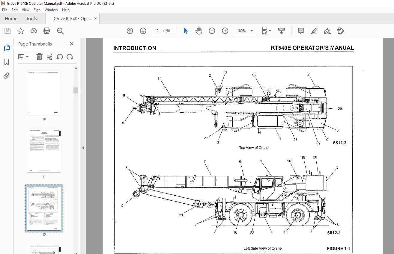
- This Handbook provides important information for the operator of the Model RT540E Series Grove
Crane. - The rough terrain crane incorporates an all welded steel frame, using planetary drive axles to
provide four-wheel drive. Axle steering is accomplished utilizing hydraulic steer cylinders. The
engine is mounted at the rear of the crane and provides motive power through a six speed forward
and reverse transmission. Hydraulic, double box, sliding beam outriggers are integral with the
frame. - The carrier frame incorporates an integral fifth wheel, to which the rear axle is mounted, to
provide axle oscillation. Axle oscillation lockout is automatic when the superstructure rotates
from the travel position. - The superstructure is capable of 360′ rotation in either direction. All crane functions are
controlled from the fully enclosed cab mounted on the superstructure. The crane is
equipped with a four-section cable synchronized full power boom. Additional reach is obtained by
utilizing a swingaway boom extension. Lifting is provided by a main hoist and an
optional auxiliary hoist.
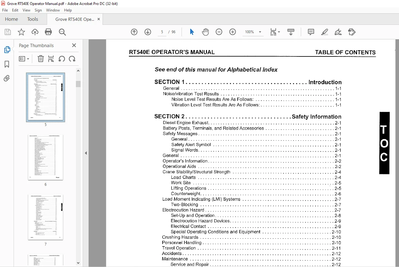
TABLE OF CONTENTS:
Grove Crane RT540E Operator’s Manual 100-01 – PDF DOWNLOAD
SECTION 1 Introduction
General 1-1
Noise/vibration Test Results 1-1
Noise Level Test Results Are As Follows: 1-1
Vibration Level Test Results Are As Follows: 1-1
SECTION 2 Safety Information
Diesel Engine Exhaust 2-1
Battery Posts, Terminals, and Related Accessories 2-1
Safety Messages 2-1
General 2-1
Safety Alert Symbol 2-1
Signal Words 2-1
General 2-1
Operator’s Information 2-2
Operational Aids 2-2
Crane Stability/Structural Strength 2-4
Load Charts 2-4
Work Site 2-5
Lifting Operations · 2-5
Counterweight 2-6
Load Moment Indicating (LMI) Systems 2-7
Two-Blocking 2-7
Electrocution Hazard 2-7
Set-Up and Operation 2-8
Electrocution Hazard Devices 2-9
Electrical Contact 2-9
Special Operating Conditions and Equipment 2-1 O
Crushing Hazards 2-1 O
Personnel Handling 2-1 O
Travel Operation 2-11
Accidents 2-12
Maintenance 2-12
Service and Repair 2-12
Lubrication 2-12
TI= ~13
Wire Rope 2-13
Batteries 2-14
Engine 2-14
Work Practices 2-14
Crane Access 2-14
Job Preparation 2-14
Working 2-15
Lifting 2-15
Hand Signals 2-16
Transporting The Crane 2-16
Shut-Down 2-16
Boom Extension/Jib 2-17
Cold Weather Operation 2-17
Temperature Effects on Hydraulic Cylinders 2-17
SECTION 3 Operating Controls and Procedures
Controls And Indicators 3-1
Tachometer with Hourmeter 3-1
GROVE TOC-1
TABLE OF CONTENTS RT540E OPERATOR’S MANUAL
TOC-2
Gauge Cluster 3-1
Voltmeter 3-1
Engine Oil Pressure Gauge 3-1
Water Temperature Gauge 3-1
Fuel Quantity Gauge 3-1
Right Turn Signal Indicator 3-1
Left Turn Signal Indicator 3-1
Four Wheel Engaged/Rear Wheels Not Centered Indicator 3-1
High Beam/Lamp Malfunction Indicator 3-1
Low Brake Pressure/Low Fuel Level Indicator 3-1
Engine Wait To Start Indicator/Transmission Service Indicator (XMSN) 3-2
Engine Warning/Electrical System Diagnostic Indicator 3-2
Engine Stop/Module Off Line Indicator 3-2
Park Brake/Swing Brake Engaged Indicator 3-2
Inter-Axle Differential Lock Indicator 3-2
Hoist 3rd Wrap Indicator (Optional w/CE) 3-2
Low Steer Pressure Indicator (CE Option) 3-6
Left Front Outrigger Beam/Stabilizer Switch 3-6
Right Front Outrigger Beam/Stabilizer Switch 3-6
Park Brake On/Off Switch 3-6
Hazard Light Switch 3-6
Headlights Switch 3-6
Work Lights Switch 3-6
Boom Lights Switch (Optional) 3-6
Heater Control Switch 3-6
Air Conditioner Switch (Optional) 3-6
Hi/Med/Low Fan Switch 3-7
Heater On/Off Switch 3-7
Fan Defroster Switch 3-7
Cross-Axle Differential Lock Switch (Optional) 3-7
Drive Axle Selector Switch 3-7
Right Rear Outrigger/Stabilizer Switch 3-7
Left Rear Outrigger/Stabilizer Switch 3-7
Emergency Stop Switch 3-7
Ignition Switch 3-7
Outrigger Extend/Retract Switch 3-8
Crane Function Power Switch 3-8
Engine Diagnostic Switches 3-8
Skylight Wiper Switch 3-8
Throttle Pedal 3-8
Hydraulic Oil Cooler Temperature Indicator 3-9
Service Brake Pedal 3-9
Transmission Shift Lever 3-9
Telescope Control Foot Pedal (Optional w/Aux Hoist) 3-9
Turn Signal Lever 3-9
Horn Button 3-9
Cab Circulating Fan 3-9
Defroster Fan 3-9
Skylight Wiper 3-9
Fire Extinguisher 3-9
Steering Column Tilt Switch 3-9
Cab Dome Light 3-9
12 VDC Accessory Outlet 3-10
360′ Swing Lock Control (Positive Lock Type) (Optional) 3-10
Electrical Diagnostic Connector 3-10
Bubble Level Indicator 3-10
Swing Brake Selector Switch 3-10
fZanlfowoc
en-,CARE
RT540E OPERATOR’S MANUAL TABLE OF CONTENTS
Auxiliary Hoist Speed Selector Switch 3-10
Telescope/ Auxiliary Hoist/Swing Controller 3-10
Swing Horn Button 3-1 O
Hoist Rotation Indicators (Main and Auxiliary Hoist) 3-10
Main Hoist Speed Selector Switch 3-10
Boom Lift/Main Hoist Controller 3-1 O
Rear Steer Control Switch · 3-11
Fuse Panel 3-11
Canister Pump Assembly 3-11
Cab Control Module 3-11
Turntable Lock Control (Pin Type) 3-11
Operating Procedures 3-12
New Crane Conditioning 3-12
Pre-Starting Checks 3-12
Cold Weather Operation 3-13
Engine Operation 3-13
Crane Travel Operation 3-15
Traveling With 7 92 m (26 ft) Boom Extension Erected 3-15
Extended Travel 3-16
Moving The Crane 3-16
Steering 3-16
Front Wheel Steering 3-16
Rear Wheel Steering 3-16
Four Wheel Steering 3-16
Crabbing 3-16
Traveling – Forward 3-17
Traveling – Reverse 3-17
Four-Wheel Drive Operation 3-17
General Crane Operation 3-17
Using Your Load Chart 3-17
Crane Functions 3-19
Operational Aids 3-23
Crane Travel Operation 3-24
Stowing and Parking 3-24
SECTION 4 Set-up And Installation Procedures
General 4-1
Installing Cable On The Hoist 4-1
Cable Reeving 4-1
Dead-end Rigging/wedge Sockets 4-5
Installing Wedge And Socket 4-5
Erecting And Stowing The Boom Extension 4-7
General Warnings 4-7
Erecting 4-7
Stowing 4-8
Setting The Offset 4-9
Changing Boom Extension From Telescoping Type To Fixed Type 4-10
Setting The Telescoping Extension Length 4-1 O
Counterweights 4-1 O
SECTION 5 Lubrication
General 5-1
Arctic Conditions Below -18°C (D°F) 5-1
Arctic Conditions Down To -40°F 5-1
Lubrication Points 5-2
Surface Protection for Cylinder Rods 5-2
GRO’VE TOC·3
TABLE OF CONTENTS RT540E OPERATOR’S MANUAL
SAFETY 5-2
STEERING & SUSPENSION Lubrication 5-4
AXLE Lubrication 5-4
DRIVE TRAIN Lubrication 5-9
OUTRIGGER Lubrication 5-9
TURNTABLE Lubrication 5-10
LIFT CYLINDER Lubrication 5-10
bOOM Lubrication 5-10
HOIST Lubrication 5-12
HYDRAULIC Lubrication 5-12
FUEL FILTER 5-12
AIR CLEANER FILTER 5-12
Wire Rope Lubrication 5-12
SECTION 6 Maintenance Checklist
General 6-1
Instructions 6-1
IMAGES PREVIEW OF THE MANUAL:
Customer Support: [email protected]
PLEASE NOTE:
- This is the SAME exact manual used by your dealers to fix your vehicle.
- The same can be yours in the next 2-3 mins as you will be directed to the download page immediately after paying for the manual.
- Any queries / doubts regarding your purchase, please feel free to contact [email protected]
S.V