Grove Crane RT600C Series Operator’s & Safety Handbook Manual – PDF DOWNLOAD
$27.95
Grove Crane RT600C Series Operator’s & Safety Handbook Manual – PDF DOWNLOAD
Description
Grove Crane RT600C Series Operator’s & Safety Handbook Manual – PDF DOWNLOAD
FILE DETAILS:
Grove Crane RT600C Series Operator’s & Safety Handbook Manual – PDF DOWNLOAD
Language : English
Pages : 140
Downloadable : Yes
File Type : PDF
DESCRIPTION:
Grove Crane RT600C Series Operator’s & Safety Handbook Manual – PDF DOWNLOAD
FOREWORD:
- This handbook has been compiled to assist you in properly operating and maintaining
your Grove Crane. - Before placing the crane in service, take time to thoroughly familiarize yourself
with the contents of this manual. After all sections have been read and understood,
retain the manual for future reference in a readily accessible location.
Tht~ Grove Crane has been designed for maximum performance with minimum
maintenance. With proper care, years of trouble-free service can be expected.
Constant improvement and engineering progress makes it necessary that we
reserve the right to make specification and equipment changes without notice. - Engine operating procedures and routine maintenance procedures are supplied
in a separate manual with each crane, and should be referred to for detailed information.
information in this manual does not replace federal, state, or local regulations,
safety codes, c>r insurance requirements.
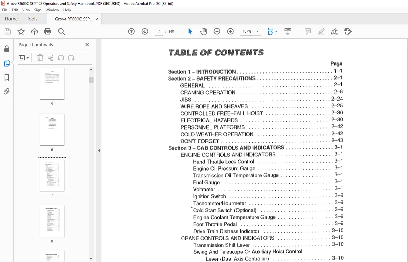
TABLE OF CONTENTS:
Grove Crane RT600C Series Operator’s & Safety Handbook Manual – PDF DOWNLOAD
SecUon 1 – INTRODUCTION 1-1
Section 2 – SAFETY PRECAUTIONS 2-1
GENERAL 2-1
CRANING OPERATION 2-6
l IBS 2-24
WIRF: ROPE ANO SHEAVES 2–25
CONTROLLED FREE-FALL HOIST 2-30
ELECTRICAL HAZARDS 2-30
PERSONNEL PLATFORMS 2-42
COLD WEATHER OPERATION 2-42
DON’T FORGET 2-43
Section 3 – CAB CONTROLS AND INDICATORS 3-1
ENGINE CONTROLS AND INDICATORS 3-·1
Hand Throttle Lock Control 3–1
Engine Oil Pressure Gauge 3-1
Transmission Oil Temperature Gauge 3-1
Fuel Gauge 3-1
Voltmeter 3-1
Ignition Swttch 3–9
Tachometer/Hourmeter 3–9
Cold Start Switch (Optional) 3-9
Engine Coolant Temperature Gauge 3-9
Foot Throttle Pedal 3-9
Drive Train Distress Indicator 3-10
CRANE CONTROLS AND INDICATORS 3–1 O
Transmission Shift Lever 3···1 O
Swing And Telescope Or Auxiliary Hoist Control
lever (Dual Axis Controller) 3-10
Telescope Or Auxiliary Hoist Control
Lever (Single Axis Controller) 3-10
Swing Control Lever (Single Axis Controller) 3–11
Rear Steer Control 3-11
Rear Steer Indicator 3-11
Boom Lift Control Lever (Single Axis Controller) 3–11
Main Haist Control lever (Single Axis Controller) 3–11
Boom Lift And Main Hoist Control
Lever (Dual Axis Controller) 3-11
Telescope Control Pedal 3-12
Mair Hoist Speed Selector Switch 3-12
Main Hoist Hi Speed Indicator 3–12
vii
TABLE OF CONTENTS (continued}
Page
Auxiliary Hoist Speed Selector Switch 3-·12
Auxiliary Hoist Hi Speed Indicator 3-‘l 2
Auxiliary Hoist On Off Switch 3-12
Hoist Rotation Indicators 3-12
Third Wrap Indicator Light 3-13
Crane Function Power Switch 3-13
Range Selector Switch 3-13
Outrigger Selector Panel 3-13
Outrigger Extension/Retraction Switch 3–13
Swing Brake Control Switch 3-14
Swing Brake Pedal 3–14
Swing Brake On Indicator 3-14
Swing Hom Button 3–14
Brake Foot Pedal 3-14
Park Brake Control Switch 3-14
Park Brake Indicator 3-14
Swing Lock Control {Pin Type) 3-15
Swing lock Control (Positive lock Type) :1 3-15
Hi Speed Glide Control Switch 3-15
Hi Speed Glide Engaged Indicator 3-15
“Emergency Steer/Brake Boost Indicator 3-15
LMI Console 3-15
ACCESSORY CONTROLS AND INDICATORS 3-15
Tow Winch Control Lever 3-·15
Work Light Switch (Optional) 3-16
Beacon Light Switch (Optional) 3–16
Boom Flood Lights Switch (Optional) 3-16
lights Switch 3-16
Fire Extinguisher 3-16
Cab Circulating Fan (Optional) 3-16
Horn 3-16
Turn Signal Lever 3-16
Four-way Flasher Switch 3-17
Steering Column Tilt Lever 3-17
Right Tum Signaf Indicator 3–17
Lett Turn Signal Indicator 3-17
Cab Interior Light 3–17
Spotlight (Optional)(Not Shown) 3-17
Armrest Adjustment Lever 3-17
viii
TABll’ OF CONTENTS (continuedJ
Page
Skylight Wiper (Optional) 3-17
Wirtdshield Wiper Switch 3-18
Bubble Laval Indicator 3-18
Heater A/C Gcmtro! Panel 3-18
Section 4- OPERATING PROCEDURES 4-1
PRE-STARTING CHECKS 4~·1
Fuel Supply 4–1
Engine Oil 4-1
Engine Coolant 4-1
Batteries 4-1
Signal and Running Lights 4-1
Foot and Parking Brakes 4-1
Daily Lubrication 4-1
Hydraulic Reservoir and Filter 4-2
Tires 4-2
Wire Rope 4-2
Hook Block 4-2
Swingaway Ex’lension 4-2
Air Cleaner 4-2
ENGINE OPERATION 4-3
Starting Procedure 4-3
Cold Weather Starting 4 -4
Idling the Engine 4-5
Racing the Engine 4-5
Shutdown Procedure 4–5
CRANE TRAVEL OPERATION 4-5
Travel-(“3eneral 4-5
Moving the Crane 4-7
Steering 4-8
Front Wheel Steering 4-8
Raar Wheel Steering 4-8
Four Wheel Steering 4-8
Crabbing 4-8
Traveling–Forward 4-9
Traveling-Reverse 4-1 O
Four Wheel Drive Operation 4-1 O
GENERAL CRANE OPERATION 4-10
Pump Drive 4-10
Setting the Park Brake When the Crane is on Outriggers 4-11
ix
TABLE OF CONTENTS (continued}
Page
Control Lever Operation 4-11
Preload Check 4-11
USING YOUR LOAD CHART 4-12
CRANE FUNCTIONS 4-14
Setting the Outriggers 4-14
Stowing the Outriggers 4-16
Swinging the Boom 4-‘l 6
Elevating and Lowering the Boom 4-17
Elevating the Boom 4-17
Lowering the Boom 4-17
Emergency Boom Operating Procedures 4-18
Telescoping the Boom 4-19
Extending the Boom 4-·19
Retracting the Boom 4-19
lowering and Raising the Cable 4–20
lowering the Cable 4-20
Raising the Cable 4-·20
Stowing and Parking 4-21
Section 5 -OPERATIONAL AIDS 5-1
GENERAL 5-1
LOA’b MOMENT INDICATING SYSTEM 5-1
CONTROL LEVER LOCKOUT SYSTEM 5–1
ANTllWO-Bl OCK SYSTEM 5-2
Section 6 – LUBRICATION 6–1
GENERAL 6-1
LUBRICATION POINTS 6–1
WIRE ROPE LUBRICATION 6-13
Section 7- SET UP AND INSTALLATION PROCEDURES 7-1
GENERAL 7-1
INSTALLING CABLE ON THE HOIST 7-1
CABLE REEVING 7-2
DEAD-END RIGGING/WEDGE SOCKETS 7-2
Installing the Wedge and Socket 7-4
)(
TABLE OF CONTENTS (continuedJ
Page
ERECTING AND STOWING THE SWINGAWAY
BOOM EXTENSION 7-6
Erectin~J 7-6
Stowing 7- 14
Setting the Offset 7-16
Setting the Telescoping Extension length 7-18
Extending 7-18
Retracting 7-19
IMAGES PREVIEW OF THE MANUAL:
Questions? Email us: [email protected]
PLEASE NOTE:
- This is the same manual used by the DEALERSHIPS to SERVICE your vehicle.
- The manual can be all yours – Once payment is complete, you will be taken to the download page from where you can download the manual. All in 2-5 minutes time!!
- Need any other service / repair / parts manual, please feel free to contact us at heydownloadss @gmail.com . We may surprise you with a nice offer
S.V