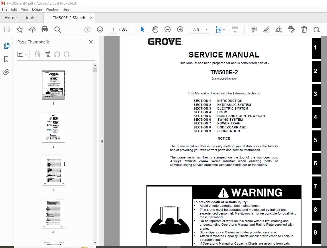
Grove Crane TM500E-2 Service Manual 151-00 – PDF DOWNLOAD
$28.95
Grove Crane TM500E-2 Service Manual 151-00 – PDF DOWNLOAD
Description
Grove Crane TM500E-2 Service Manual 151-00 – PDF DOWNLOAD
FILE DETAILS:
Grove Crane TM500E-2 Service Manual 151-00 – PDF DOWNLOAD
Language : English
Pages : 386
Downloadable : Yes
File Type : PDF
IMAGES PREVIEW OF THE MANUAL:
TABLE OF CONTENTS:
Grove Crane TM500E-2 Service Manual 151-00 – PDF DOWNLOAD
SECTION 1 INTRODUCTION
SECTION 2 HYDRAULIC SYSTEM
SECTION 3 ELECTRIC SYSTEM
SECTION 4 BOOM
SECTION 5 HOIST AND COUNTERWEIGHT
SECTION 6 SWING SYSTEM
SECTION 7 POWER TRAIN
SECTION 8 UNDERCARRIAGE
SECTION 9 LUBRICATION
SECTION 1 Introduction
Description 1-1
List of Specifications 1-1
General 1-1
Dimensions 1-1
Capacities 1-1
Superstructure Engine 1-1
Swing Gearbox 1-1
Boom 1-1
Swivel Assembly 1-1
Hydraulic Pumps 1-2
General Maintenance 1-5
Cleanliness 1-5
Removal and Installation 1-5
Disassembly and Assembly 1-5
Pressing Parts 1-5
Locks 1-5
Wires and Cables 1-6
Shims 1-6
Bearings 1-6
Gaskets 1-6
Batteries 1-6
Hydraulic Systems 1-7
Electrical System 1-8
Fatigue of Welded Structures 1-8
Loctite 1-8
Fasteners and Torque Values 1-9
Dynamic Shock Loads 1-10
Wire Rope 1-12
General 1-12
Environmental Conditions 1-12
Lubrication 1-13
Precautions and Recommendations During Inspection or Replacement 1-13
Wire Rope Inspection (Running Ropes and Pendant Cables) 1-14
Wire Rope Inspection (Boom Extension and Retraction Cables) 1-14
Wire Rope Replacement (All Wire Rope) 1-15
Seizing Wire Rope 1-15
Installing FLEX-X 35 Wire Rope 1-16
Procedures for Cutting and Preparing FLEX-X 35 1-17
SECTION 2 Hydraulic System
Description 2-1
Maintenance 2-4
Hydraulic Oil Recommendations 2-4
Draining and Flushing 2-4
Removing Air from the Hydraulic System 2-4
Parts Replacement 2-5
Directional Control Valves 2-5
Supply Pressure and Return Circuit 2-7
Description 2-7
Maintenance 2-8
Oil Cooler 2-12
Description 2-12
Hydraulic Pumps 2-13
TABLE OF CONTENTS TM500E-2 SERVICE MANUAL
TOC-2
Description 2-13
Maintenance 2-13
Pressure Setting Procedures 2-16
Procedure A – For Checking/Setting The Main Control Valve For Hoists(s),
Boom Lift and Piston Pump 2-17
Procedure B – For Setting The Outrigger & Swing Pressures 2-18
Procedure C- For Checking/Setting the Pilot Supply Pressure 2-18
Procedure D – For Checking/Setting the Swing Brake Release Pressure 2-18
Procedure E- For Setting Threshold on Electronic Controllers 2-18
Valves 2-23
General 2-23
Directional Control Valves 2-26
Description 2-26
Maintenance 2-26
Accessory With Swing Directional Control Manifold 2-29
Description 2-29
Maintenance 2-29
Holding Valves 2-33
Description 2-33
Maintenance 2-33
Outrigger Control Manifold 2-34
Description 2-34
Maintenance 2-34
Pilot Operated Check Valve 2-35
Description 2-35
Maintenance 2-35
Outrigger Selector valve 2-36
Description 2-36
Maintenance 2-36
Cylinders 2-38
General 2-38
Maintenance 2-38
Surface Protection for Cylinder Rods 2-38
Lift Cylinder 2-40
Description 2-40
Maintenance 2-40
Dual Rod Telescope Cylinder (102 Foot Boom) 2-43
Description 2-43
Maintenance 2-43
Telescope Cylinder (28 9m [95 Foot] Boom) 2-47
Description 2-47
Maintenance 2-47
Outrigger Extension Cylinder 2-52
Description 2-52
Maintenance 2-52
Outrigger Stabilizer Cylinder 2-55
Description 2-55
Maintenance 2-55
SECTION 3 Electric System
Superstructure 3-1
Description 3-1
Batteries 3-1
Fuse Panel 3-2
Relays 3-2
Maintenance 3-3
TOC-3
TM500E-2 SERVICE MANUAL TABLE OF CONTENTS
T
OC
Carrier Electrical Features 3-10
Introduction 3-10
Design and Function 3-11
Instrumentation Component Location 3-11
Carrier Electrical Center (CEC) 3-11
Additional Electrical Information – Typical Circuit Components 3-12
Specifications 3-13
Special Torque Chart 3-13
Diagnostic Equipment 3-13
Repair 3-14
Relay Replacement 3-16
Replace Fusible Link (Battery-Side) 3-16
Troubleshooting 3-16
Troubleshooting Wiring and Connectors 3-16
Data LInk Communication 3-21
Introduction 3-21
Design and Function 3-21
Data Link 3-21
Troubleshooting 3-25
Repair 3-28
Electrical Features 3-30
Introduction 3-30
Design and Function 3-30
Special Tools and Equipment 3-30
Repair 3-30
Troubleshooting 3-32
Instrumentation System Schematic 3-34
Diagnostic Troubleshooting Table 3-35
Gauge Tester Function Table 3-36
Gauge Data Source Table 3-37
SECTION 4 Boom
Description 4-1
Safety 4-1
Boom System Components 4-1
Telescope Cylinder 4-1
Fly Section Extension Cables 4-1
Extend Synchronizing Cable 4-1
Fly Retraction Cables 4-1
Outer Mid Retract Cables 4-1
Boom Extension Sequence 4-1
Boom Retract Sequence 4-3
Telescope Circuit 4-3
Description 4-3
Theory Of Operation 4-3
Lift Circuit 4-3
Description 4-3
Theory Of Operation 4-4
General Maintenance Notes 4-4
Swingaway Extension Removal 4-4
Boom Removal 4-5
Boom Disassembly for the Standard 31 m (102 foot) Boom 4-7
Disconnect the Base Section 4-7
Remove the Base Section 4-8
Disconnect the Inner Mid Section 4-9
Remove the Inner Mid Section 4-10
TABLE OF CONTENTS TM500E-2 SERVICE MANUAL
TOC-4
Remove the Outer Mid Section 4-12
Remove the Tele Cylinder 4-14
Extend Cable Sheave Removal 4-15
Boom Nose Sheaves 4-16
Boom Nose Sheaves Removal 4-16
Boom Nose Sheaves Installation 4-16
Boom Assembly Procedure for the 31 m (102 foot) Boom 4-17
Extend Cable Sheave Installation 4-17
Install Telescope Cylinder 4-17
Install the Outer Mid Section 4-19
Install the Inner Mid Section 4-23
Install the Base Section 4-29
Boom Disassembly for the Optional 29 m (95 foot) 4-31
Remove the Base Section 4-31
Disconnect Inner Mid Section 4-33
Remove the Inner Mid Section 4-34
Remove Outer Mid Section 4-35
Remove Telescope Cylinder 4-37
Boom Nose Sheaves 4-38
Boom Assembly for the Optional 29 m (95 Foot) Boom 4-38
Install Telescope Cylinder 4-38
Install Outer Mid Section 4-39
Install Inner Mid Section 4-41
Connect Inner Mid Section 4-42
Install Base Section 4-43
Boom Installation 4-44
Swingaway Extension Installation 4-44
Boom Cable Adjustment for the 31 m (102 foot) Boom 4-47
Extend Cable Adjustment 4-47
Retract Cable Adjustment 4-48
Boom Cable Adjustment for the 29 m (95 foot) Boom 4-48
Extend Cable Adjustment 4-48
Retract Cable Adjustment 4-49
Boom Maintenance 4-49
Functional Test Of The Boom 4-49
Boom Inspection 4-49
Boom Alignment And Servicing 4-49
Extension And Retraction Cable Maintenance 4-50
Inspection 4-50
Telescope Circuit Troubleshooting 4-52
Lift Circuit Troubleshooting 4-54
Lift Cylinder Maintenance 4-56
Lift Cylinder Removal 4-56
Lift Cylinder Disassembly And Assembly 4-56
Lift Cylinder Installation 4-56
SECTION 5 Hoist And Counterweight
Description 5-1
Theory of Operation 5-1
Warm-up Procedure 5-1
Maintenance 5-1
Removal 5-3
Installation 5-4
Functional Check 5-5
Servicing 5-5
Hoist to Boom Alignment 5-6
TOC-5
TM500E-2 SERVICE MANUAL TABLE OF CONTENTS
Preparation 5-6
Tools Required 5-6
Procedure 5-6
Piston Motor and Control Valve 5-7
Description 5-7
Maintenance 5-7
Idler Drum and Cable Follower 5-8
Description 5-8
Maintenance 5-8
Hoist Drum Rotation Indicator System 5-11
Description 5-11
Maintenance 5-11
Counterweight Removal 5-13
Description 5-13
Description 5-13
Removal 5-13
Installation 5-13
SECTION 6 Swing System
Introduction 6-1
Description 6-1
Theory of Operation 6-1
Maintenance 6-4
Troubleshooting 6-4
Swing Motor 6-7
Description 6-7
Maintenance 6-7
Swing Gearbox And Brake 6-8
Description 6-8
Maintenance 6-8
Swing Bearing 6-10
Description 6-10
Maintenance 6-10
Swivels 6-16
Description 6-16
Hydraulic Swivel 6-18
Electrical Swivel 6-19
SECTION 7 Power Train
Engine 7-1
Description 7-1
Maintenance 7-1
Electronic Controls 7-6
Engine Wait To Start /Battery Discharge Indicator 7-6
Engine Warning/Electrical System Diagnostic Indicator 7-6
Engine Stop/Module Off Line Indicator 7-6
Fuel System 7-7
Description 7-7
Maintenance 7-7
Air Intake System 7-9
Description 7-9
Maintenance 7-9
Water Cooling System 7-14
Description 7-14
Maintenance 7-14
Test Equipment 7-17
TABLE OF CONTENTS TM500E-2 SERVICE MANUAL
TOC-6
Antifreeze/Coolant 7-18
Radiator Removal and Installation 7-18
SECTION 8 Undercarriage
Driveshaft and Shaft Phase Angles 8-1
Specifications 8-1
Driveshaft 8-1
Half-Round End Yoke 12-point Bolt Specifications 8-1
Maximum Driveshaft Operating Angle 8-1
Driveshaft Phase Angles 8-1
Interaxle Driveshaft Phase Angle 8-1
Design and Function 8-2
Driveshafts 8-2
Driveshaft Function 8-2
Construction of a Driveshaft 8-3
Example of Spline Galling 8-3
Universal Joints 8-3
Input Yoke 8-3
Half-Round End Yoke 8-4
Driveshaft Center Bearing 8-4
Correcting Universal Joint Operating Angles 8-4
Typical Chart to Record Driveshaft/Yoke Angles 8-4
Cutaway View of Center Bearing 8-4
Typical Axle Housing Shims 8-4
Balancing a Driveshaft 8-5
Driveshaft Angles and Phasing 8-5
Driveshaft Arrows Lined Up “in phase” 8-5
Driveshaft Troubleshooting 8-6
Causes of Universal Joint Operating Angle Changes 8-7
Vibration-related Problems 8-7
First Order Vibration 8-7
Second order vibration 8-7
Lubrication Related Problems 8-7
Typical Lack of Lubrication 8-7
Typical Trunnion Brinelling 8-7
Typical End Galling 8-8
Bearing Cup Rotation Troubleshooting 8-8
Repair 8-8
Driveshaft, Removal 8-8
Removal (Half-round End Yoke Style) 8-8
Universal Joint, Replacement 8-9
Disassembly 8-9
Assembly (Half-round) 8-10
Driveshaft, Installation 8-13
Installation, Half-Round End Yoke Style 8-13
Maintenance 8-14
Driveshaft, Lubrication 8-14
Lubrications for Universal Joints 8-14
Initial Lubrication and Relube Cycle 8-14
Driveshaft Support Bearing Assemblies 8-15
Driveshaft Maintenance Intervals 8-15
Universal Joint, Checking 8-15
Universal Joint, Lubrication 8-18
U-Joints 8-18
Slip Splines 8-18
Driveshaft Angles, Checking 8-19
TOC-7
TM500E-2 SERVICE MANUAL TABLE OF CONTENTS
T
OC
Tools: Electronic Protractor 8-19
Preparing the crane 8-19
Procedure 8-19
Pinion Angles, Correcting 8-20
Wheel Bearing Adjustment 8-21
Introduction 8-21
Adjusted Wheel End Systems 8-21
Crane Hub Unit 8-21
Nut Adjustment Torque Specifications 8-21
Repair 8-22
Wheel Bearing Adjustment 8-22
Jam Nut Torque 8-22
Determining Acceptable End Play Using a Dial Indicator 8-22
Steering Linkage and Wheel Alignment Information 8-23
Wheel Alignment Measurement Specifications 8-23
Design & Function 8-24
Steering Assembly 8-24
Tie Rod 8-24
Tie Rod Arms 8-25
Steering Arms 8-25
Draglink 8-25
Steering Gear and Pitman Arm 8-25
Steering Column / Steering Shaft 8-26
Steering Wheel 8-26
Wheel Alignment Overview 8-26
Checking Air Pressure 8-27
Checking Lug Nut Torque 8-27
Front Suspension 8-27
Rear Axle and Rear Suspension 8-27
Front Wheel Alignment Terminology 8-27
Caster 8-27
Camber 8-28
Toe-In / Toe-Out 8-29
Turning Angles 8-29
Rear Wheel Alignment Overview 8-30
Thrust Angle 8-30
Tandem Scrub Angle 8-31
Typical Wear Patterns 8-31
Incorrect Tire Pressure 8-31
Incorrect Camber 8-31
Incorrect Toe and Axle Alignment 8-31
Dual-Wheel Mounting 8-32
Incorrect Caster and Wheel Imbalance 8-32
Cuts In the Tire Tread 8-32
Spot Wear 8-32
Feathered Edges 8-33
Cupping 8-33
Repair Information 8-33
Ball Joint Wear Inspection 8-33
Toe Adjustment 8-34
Turn Angle Adjustment 8-35
Caster Adjustment 8-35
Drive Axle Thrust Angle Adjustment 8-36
Important Safety Information Before Making Ride Height Adjustment 8-38
Shock Absorbers 8-38
Air Spring Inflation And Deflation 8-38
Air Spring Inflation 8-38
TABLE OF CONTENTS TM500E-2 SERVICE MANUAL
TOC-8
Air Spring Deflation 8-38
Support Beam And Cross Brace Assembly 8-38
Cross Brace Assembly 8-38
Ride Height Adjustment 8-38
Adjustment Procedure 8-40
Lateral Alignment 8-40
Axle Pinion Angle 8-41
Drive Axle Alignment Inspection Procedure 8-41
Ride Height Alignment Instructions 8-42
Ride Height Pinion Angle Adjustment 8-44
Adjustment Of More Than 1 5 Degrees 8-44
Steering Hydraulic System 8-44
Specifications 8-45
Steering Gear 8-45
Steering Pump 8-45
Steering Fluid 8-45
Test and Adjustment 8-46
Special Torque Chart 8-46
Special Tools And Equipment 8-46
Special Equipment 8-46
Hydraulic Flow Meter 8-46
Design and Function 8-47
Steering Hydraulic System 8-47
Steering Pump 8-47
Power Steering Gear 8-48
Steering Geometry 8-48
Fluid Reservoir and Filter 8-49
Troubleshooting 8-49
Tests and Adjustments Steering Hydraulic System 8-51
Preparation 8-51
Testing Pump Pressure 8-51
Testing Pump Flow 8-51
Testing Steering Gear Internal Leakage 8-52
Steering Knuckle 8-52
Adjusting Steering Gear Relief Valve 8-52
Repair 8-52
Replacing Power Steering Pump 8-52
Removal 8-52
Installation 8-53
Replacing Steering Gear 8-53
Removal 8-53
Installation 8-53
Replacing Steering Fluid Filter 8-54
Changing Power Steering Fluid 8-54
Bleeding Steering Hydraulic System 8-54
Overhauling Steering Assist Cylinder 8-55
Preparation Before Disassembly 8-55
Disassembly 8-55
Assembly 8-55
ABS System General Information 8-56
Anti-Lock Brake System 8-56
ABS System Electronic Control Unit 8-56
Anti-Lock Brake System Description 8-56
Traction Control System 8-57
Components 8-57
Tooth Wheel 8-58
Sensor 8-58
TOC-9
TM500E-2 SERVICE MANUAL TABLE OF CONTENTS
T
OC
Modulator Valve 8-59
Anti-Lock Modulator Valve 8-59
ATR-1 Relay Valves 8-59
Electronic Control Unit (ECU) 8-60
ECU Connections 8-60
Inputs 8-62
Outputs 8-62
Configuration Information 8-62
Pass-through Connector 8-62
ABS Warning Lamp 8-63
Automatic Traction Control 8-64
ATC Lamp and Switch 8-64
ABS Self-tests 8-65
ABS Fault Detection 8-65
Test and Adjustments 8-65
Traction Control Valve Function Check 8-65
Traction Control Valve Differential Pressure Check 8-66
Traction Control Valve Solenoid Check 8-66
System Diagrams 8-67
System Schematic Detail 8-68
ABS System Schematic, Relays and Connectors 8-69
Repair Information 8-70
ABS Sensor Adjustment 8-70
Wheel Speed Sensor Replacement (Front) 8-70
Wheel Speed Sensor, Replacement (Rear) 8-72
Front Modulator Valve Replacement 8-73
Rear Modulator Valve Replacement 8-74
ATR Valve Replacement 8-75
ABS Electronic Control Unit Replacement 8-76
ABS Troubleshooting 8-76
General 8-76
General Safety Information 8-76
Data Link Instrument Cluster – Diagnostic Display 8-77
Diagnostic Messages 8-77
MPSI Pro-Link 9000 8-77
AL-6 8-77
AL-7 8-77
Readout Window 8-78
Keypad 8-78
Push Button 8-78
Installing and Removing the MPC Cartridge 8-78
Non-Volatile Memory 8-79
MPSI Power/Data Cable 8-79
Connecting the Power/Data Cable 8-79
Fuse 8-79
Application Cards 8-79
Installing the Application Card: 8-80
Using the Pro-Link 9000 8-80
Bendix ABS Application Card and MPC Cartridge (with AL-7 ECU) 8-80
MPC Application Menu Structure 8-83
Using the Bendix ABS Cartridge (with AL-6 ECU) 8-84
System Testing Using the Pro-Link 9000 (AL-6) 8-85
Preparing for Testing 8-85
ECU LEDs 8-87
Diagnosing Faults Using the ECU LEDs 8-87
Troubleshooting Quick Reference 8-88
Component Troubleshooting Quick Reference Chart 8-89
TABLE OF CONTENTS TM500E-2 SERVICE MANUAL
TOC-10
Initial Start-up Procedure for AL-6 / EC-16 or AL-7 / EC-17 ECU 8-90
Section I – ABS Warning Lamp Testing 8-91
Section II – Inspection for Illuminated LEDs 8-92
Section III – Inspection for Illuminated LEDs 8-93
Section IV – Inspection for Illuminated LEDs 8-94
Section V – Testing for Power to the ABS ECU 8-95
Section VI A – Testing the Modulator Valve 8-96
Section VI B – Testing the Modulator Valve 8-97
Section VII A – Testing the Wheel Speed Sensor 8-98
Section VII B – Testing the Wheel Speed Sensor 8-99
Section VIII – Testing for False Indication Caused by ABS Warning Lamp Relay 8-100
Section IX – Testing for False Indication Caused by Wheel Speed Components 8-101
Section X – Testing TCS Lamp 8-102
Section XI – Testing Traction Control Valve 8-103
Section XII – Testing J1922 Circuit 8-104
Outriggers 8-105
Outrigger Circuit Description 8-105
Outrigger Beam Description 8-108
Inspection 8-111
Installation 8-111
Wear Pad Adjustment 8-111
Extension Cylinder Description 8-112
Stabilizer Cylinder Description 8-113
Outrigger Control Valve Description 8-114
Table of Contents 9-i
SECTION 9 Lubrication
General 9-1
Arctic Conditions Below -18°C (0°F) 9-1
Lubrication Points 9-1
Surface Protection For Cylinder Rods 9-1
Safety 9-2
Carrier Lubrication 9-3
Superstructure Lubrication 9-7
Boom, Boom Extension, and Boom Accessories Lubrication 9-9
Wire Rope Lubrication 9-11
S.V 08/24