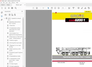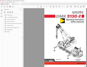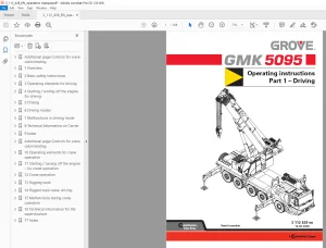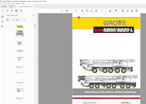
Grove Crane TMS 700E Series Superstructure Operator’s & Safety Handbook Manual – PDF DOWNLOAD
$19.95
Grove Crane TMS 700E Series Superstructure Operator’s & Safety Handbook Manual – PDF DOWNLOAD
Description
Grove Crane TMS 700E Series Superstructure Operator’s & Safety Handbook Manual – PDF DOWNLOAD
FILE DETAILS:
Grove Crane TMS 700E Series Superstructure Operator’s & Safety Handbook Manual – PDF DOWNLOAD
Language : English
Pages : 86
Downloadable : Yes
File Type : PDF
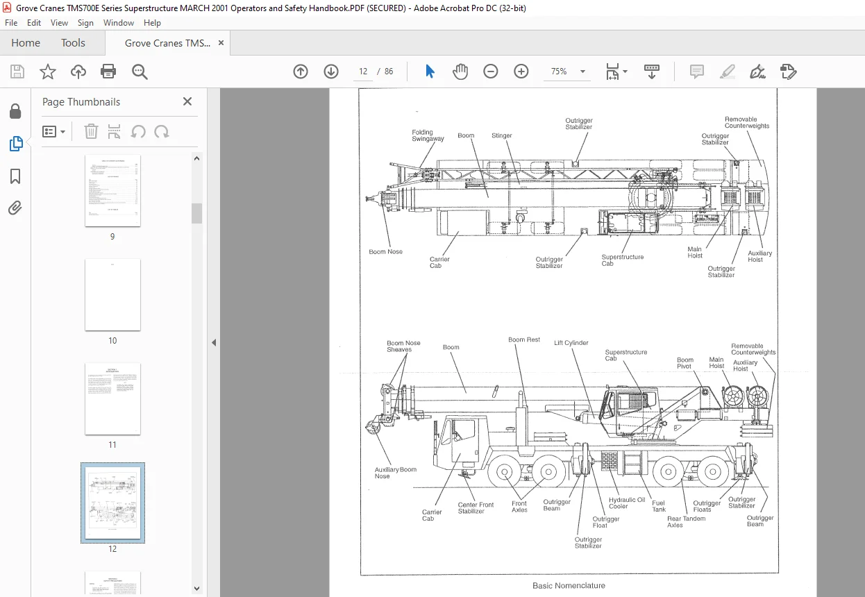
IMAGES PREVIEW OF THE MANUAL:
DESCRIPTION:
Grove Crane TMS 700E Series Superstructure Operator’s & Safety Handbook Manual – PDF DOWNLOAD
FOREWORD:
- This handbook ~as been compiled to assist you in properly operating and maintaining your Grove Crane.
- Before placing the crane in service, take time to thoroughly familiarize yourself with the contents of this manual. After all sections have been read and understood, retain the manual for future reference in a readily accessible location.
- The Grove Crane has been designed for maximum performance with minimum maintenance. With proper care, years of trouble-free service can be expected.
- Constant improvement and engineering progress makes it necessary that we reserve the light to make specification and equipment changes without notice.
- Grove Worldwide and our Dealer Network want to ensure your satisfaction with our products and customer support.
Your local dealer is the best equipped and most knowledgeable to assist you for parts, service and warranty issues. - They have the facilities, parts, factory trained personnel, and the information to assist you in a timely manner. We request that you first contact them for assistance. If you feel you need factory assistance, please ask the dealer’s service management to coordinate the contact on your behalf.
- Engine operating procedures and routine maintenance procedures are supplied in a separate manual with each crane, and should be referred to for detailed information.
- Information in this manual does not replace federal, state, or local regulations, safety codes, or insurance requirements.
- The definitions of DANGER, CAUTION, and NOTE as used in this manual apply as follows .
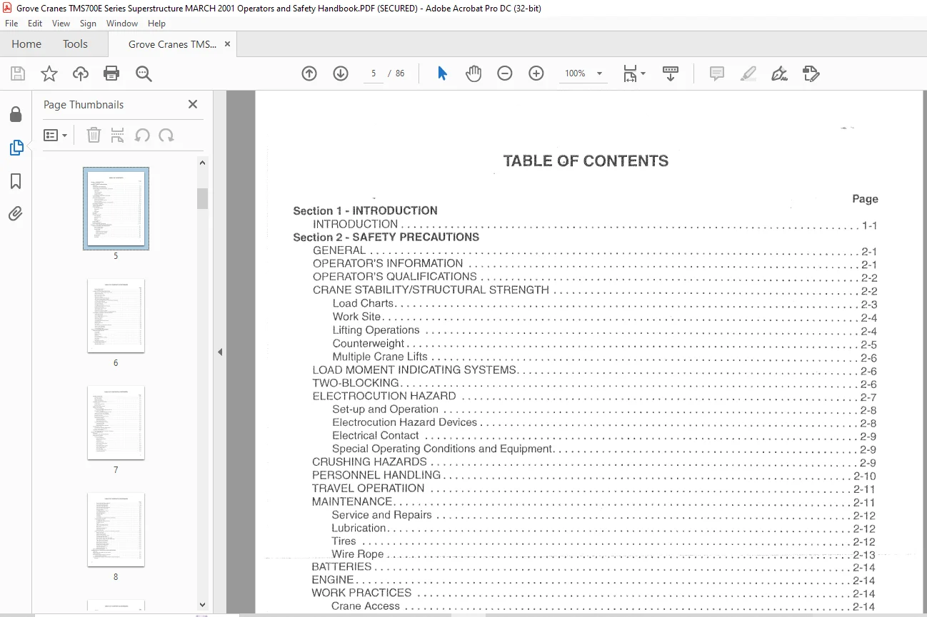
TABLE OF CONTENTS:
Grove Crane TMS 700E Series Superstructure Operator’s & Safety Handbook Manual – PDF DOWNLOAD
Section 1 INTRODUCTION
INTRODUCTION 1-1
Section 2 – SAFETY PRECAUTIONS
GENERAL 2-1
OPERATOR’S INFORMATION 2-1
OPERATOR’S QUALIFICATIONS 2-2
CRANE STABILITY/STRUCTURAL STRENGTH 2-2
Load Charts 2-3
Work Site · 2-4
Lifting Operations 2-4
Counterweight 2-5
Multiple Crane Lifts 2-6
LOAD MOMENT INDICATING SYSTEMS 2-6
TWO-BLOCKING 2-6
ELECTROCUTION HAZARD 2-7
Set-up and Operation 2-8
Electrocution Hazard Devices 2-8
Electrical Contact 2-9
Special Operating Conditions and Equipment 2-9
CRUSHING HAZARDS 2-9
PERSONNEL HANDLING 2-10
TRAVEL OPERATIION 2-11
MAINTENANCE 2·11
Service and Repairs 2-12
Lubrication 2-12
Tires 2-12
Wire Rope , ··········· ” – , , – -, · · · — , _ , ;·· -~ ; ·;·;··;··;· ·2-13
BATTERIES 2-14
ENGINE 2-14
WORK PRACTICES 2-14
Crane Access 2-14
Job Preparation 2-14
Working ; 2-15
Lifting 2-15
Hand Signals 2-16
SHUT-DOWN 2-17
BOOM EXTENSION 2-17
COLD WEATHER OPERATION 2-18
Section 3 – CAB CONTROLS AND INDICATORS
ENGINE CONTROLS AND INDICATORS 3-1
Hand Throttle Control 3-i
Throttle Mode Switch 3-1
Gauge Cluster 3-1
Voltmeter 3-1
Engine Oil Pressure Gauge 3-1
Water Temperature Gauge 3-1
Fuel Quantity Gauge 3-i
Ignition Switch 3-1
Tachometer 3-5
Hourmeter 3-5
V
TABLE OF CONTENTS (CONTINUED)
Page
Engine Stop Indicator 3-5
Foot Throttle Pedal 3-5
CRANE CONTROLS AND INDICATORS 3-5
Telescope or Auxiliary Hoist Control Lever 3-5
Swing Control Lever 3-5
Boorr1 Lift Control Lever 3-5
Main Hoist Control Lever 3-5
Swing Horn Button 3-5
Telescope Control Pedal (Optional) 3-5
Main Hoist Speed Selector Switch 3-5
Auxiliary Hoist Speed Selector On/Off Switch (Optional) 3-5
Hoist Rotation Indicators 3-6
Crane Function Power Switch 3-6
Hoist Boost Switch 3-6
Outrigger Control Box 3-6
Front Stabilizer Overloaded Indicator 3-7
Bubble Level Indicator 3-7
Swing Brake Control Switch 3-7
Swing Brake Pedal 3-7
Swing Lock Control (Pin Type) 3-7
Swing Lock Control (Positive Lock Type) (Optional) 3-7
ACCESSORY CONTROLS AND INDICATORS 3-7
Panel Light Control 3-7
Work Lights Switch 3-7
Boom Lights Switch (Optional) 3· 7
Cab Circulating Fan 3-7
Cab Dome Light-· “‘”·· “‘” — – – -,- – , –,— — -,– — — – – – -,– – – — – –,–,- -, ;- -·-;·-;- ·- – ;-·;-··3-7-
Fire Extinguisher 3-7
Windshield Wiper/Washer Switch 3-7
Skylight Wiper 3-7
Heat Control Knob 3-8
Fan Switch ,, 3-8
Air Conditioner Control Switch (Optional) 3-8
Beacon Light (Optional) 3-8
12 vdc Accessory Outlet – 3-8
Circuit Breaker Panel 3-8
Section 4 OPERATING PROCEDURES
PRE-STARTING CHECKS 4-1
Fuel Supply 4-i
Engine Oil 4-1
Engine Coolant 4-1
Batteries 4-1
Daily Lubrication 4-1
Hydraulic Reservoir and Filter 4-1
Wire Rope 4-1
Hookblock 4-1
Swingaway Extension 4-1
COLD WEATHER OPERATION 4-1
Operation Below -40 °C 4-2
Operation Below -40 °F 4-2
vi
TABLE OF CONTENTS (CONTINUED)
Page
ENGINE OPERATION 4-2
Starting Procedure 4-2
Idling the Engine 4-3
Racing the Engine 4-3
Shutdown Procedure 4-3
GENERAL CRANE OPERATION 4-3
Pump Drive 4-3
Control Lever Operation 4-3
Preload Check 4-3
USING YOUR LOAD CHART 4-3
CRANE FUNCTIONS 4-5
Setting the Outriggers 4-5
Engaging the Mid-Extension lock Pin 4-6
Stowing the Outriggers 4-6
Stowing the Mid-Extension Lock Pin 4-7
Setting the Center Front Stabilizer 4-7
Stowing the Center Front Stabilizer 4-7
Swinging the Boom 4-8
Elevating and Lowering the Boom 4-8
Telescoping the Boom 4-8
Extending the Boom 4-8
Retracting the Boom 4-9
Telescope Control Pedal 4-9
Lowering and Raising the Cable 4-9
Lowering the Cable 4-9
Raising the Cable 4-9
Hoist Speed Range Selection ,___ , , y············ ,·································· , ,·4-9
OPERATIONAL AIDS 4-9
Load Moment Indicating (LMI) System 4-9
Control Lever Lockout System 4-10
STOWING AND PARKING 4-10
Recommended Crane Shutdown Procedures 4-11
Section 5 – LUBRICATION
GENERAL 5-1
LURICANTS AND SPECIFICATIONS 5-1
LUBRICATION POINTS 5-6
Carrier Lubrication 5-7
Engine Crankcase 5-7
Engine Cooling System 5-7
Transmission 5-7
Pump Drive 5-7
Pump Drive Shaft 5-9
Clutch Throw Out Bearing 5-9
Clutch Linkage 5-9
Transmission Shift U-Joints 5-9
Power Steering Gearbox 5-9
Steering Relay Arms 5-9
Front Axle Hubs 5-9
Front Axle Tie Rod Ends 5-9
Front Axle King Pins 5-9
vii
TABLE OF CONTENTS (CONTINUED)
Page
Front Axle Brake Slack Adjusters 5-9
Front Axle Brake Camshafts 5-9
Front Rear Axle Differential 5-9
Rear Rear Axle Differential 5-10
Rear Axle Brake Slack Adjusters 5-10
Rear Axle Brake Camshafts 5-10
Outrigger Beams 5-10
Jack Cylinder Support Tubes 5-10
Jack Cylinder Barrels 5-i0
Hydraulic Reservoir 5-10
Hydraulic Filter 5-1 0
Fuel Filter 5-10
Air Cleaner 5-1 0
Coolant Strainer (Superstructure Cab Heater) 5-1 0
Superstructure Lubrication 5-10
Turntable Gear Box 5-10
Turntable Gear And Drive Pinion 5-11
Turntable Bearing 5-11
Swivel 5-11
Upper Lift Cylinder Pivot Pin 5-11
Lower Lift Cylinder Pivot Pin 5-11
Main Hoist 5-1 i
Auxiliary Hoist (Optional) 5-12
Hoist Cable Follower 5-12
Hoist Cable Idler 5-12
Boom, Boom Extension, and Boom Accessories Lubrication 5-12
________ ·——·-·- BoomJ’ivot Shaft – – – -,-, ·, – -··,–,-~– — – –,- -·, , , , , ,–,· · – · -,- ·-· – -;—,– –; -· –; – , ;-5-1-2·–
Extend Cable Sheaves 5-12
Retract Cable Sheaves 5-12
Telescope Cylinder Wear Pads 5-12
Inner Mid Side Wear Pads 5-12
Boom Section Upper Rear Wear Pads 5-12
Boom Section Upper and Lower Wear Pads 5-12
Upper Boom Nose Sheaves 5-12
Lower Boorn Nose Sheaves 5-12
Boom Extension Sheaves 5-12
Boom Extension Mast Sheave 5-14
Auxiliary Boom Nose Sheave 5-14
Hook Block Swivel Bearing 5-14
Hook Block Sheaves , 5- i 4
Headache Ball Swivel Top 5-i4
WIRE ROPE LUBRICATION 5-14
Section 6 – SET UP AND INSTALLATION PROCEDURES
GENERAL 6-1
INSTALLING THE CABLE ON THE HOIST 6-1
CABLE REEVING 6-1
DEAD-END RIGGING/WEDGE SOCKETS 6-6
Installing Wedge and Socket 6-7
ERECTING AND STOWING SWINGAWAY BOOM EXTENSION 6-8
Erecting 6-8
viii
TABLE OF CON’TENTS (CONTINUED)
Page
Stowing 6-15
Setting The Folding Swingaway Offset 6-17
ERECTING AND STOWING SWINGAWAY BOOM EXTENSION USING THE 6 1 M (20 FOOT)
AND/OR 12 2 M (40 FOOT} INSERT 6-18
Erecting 6-18
Stowing 6-18
REMOVABLE COUNTERWEIGHT 6-20
Mounting the Counterweight 6-20
Stowing the Counterweight · 6-20
Need help? Contact: [email protected]
PLEASE NOTE:
- This is the SAME manual used by the dealers to troubleshoot any faults in your vehicle. This can be yours in 2 minutes after the payment is made.
- Contact us at [email protected] should you have any queries before your purchase or that you need any other service / repair / parts operators manual.
S.V